Manual Guide 16i/18i/21i - TA Operators manual Page 52
Operators manual
4.GUIDANCE CUTTING OPERATIONSOPERATION B-63344EN/02
- 40 -
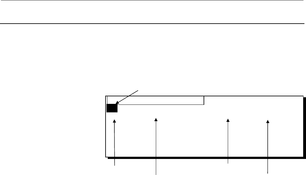
4.6.2 Whole Processes Playback Machining
In order to use taught-in blocks for whole processes playback
machining, it is necessary to save them into CNC memory as a
playback machining program.
• Operations for saving as a new playback program
1) Push [SAVE], and a Program List is displayed in a pop-up
window.
2) Input 2 digits number for program number, and push
[NEW]. After then, a new program including current
taught-in blocks is made.
3) Move a cursor onto the program name field, and Input
program name through key-board, and push INPUT. The
maximum character number of it is 20.
• Operations for adding to an old playback program
1) Push [SAVE], and a Program List is displayed in a pop-up
window.
2) Select the program into which current taught-in blocks are
added by positioning a cursor to its program number.
3) Push [ADD], and after then, the current taught-in blocks are
added the end of the selected playback program.
Processing time
(Max
99minuites)
Program
Cursor
Program Name
(Max 20ch.)
Lastly modified
date and time
PROGRAM LIST
O0: CIRCLE MACHINING 5M12S 1997/05/12 10:12
10:LINE MACHINING 4M32S 1997/06/10 11:21
01
Contents Summary of Manual Guide 16i/18i/21i - TA Operators manual
- Page 1GE Fanuc Automation Europe Computer Numerical Controls Manual Guide for Lathe Operator's Manual B-63344EN/02 TECHNOLOGY AND MORE�
- Page 2Ȧ No part of this manual may be reproduced in any form. Ȧ All specifications and designs are subject to change without notice. In this manual we have tried as much as possible to describe all the various matters. However, we cannot describe all the matters which must not be done, or which cannot be
- Page 3B-63344EN/02 SAFETY PRECAUTIONS SAFETY PRECAUTIONS This manual includes safety precautions for protecting the user and preventing damage to the machine. Precautions are classified into Warnings and Cautions according to their bearing on safety. Also, supplementary information is described as Notes.
- Page 4SAFETY PRECAUTIONS B-63344EN/02 1.1 FOR SAFETY DURING OPERATION To ensure safety while using a machine featuring the MANUAL GUIDE function that is made according to this programming manual, observe the following precautions: WARNING 1 Confirm, on the screen, that the data has been entered correctly
- Page 5B-63344EN/02 TABLE OF CONTENTS TABLE OF CONTENTS SAFETY PRECAUTIONS .......................................................................... s-1 I. GENERAL 1 OVERVIEW ............................................................................................3 2 GUIDANCE HANDWHEEL.................
- Page 6TABLE OF CONTENTS B-63344EN/02 4.4 EDITING TAUGHT-IN BLOCKS ..................................................................36 4.4.1 Figure Data Window ............................................................................................. 36 4.4.2 Operations for Figure Data Editing ........
- Page 7B-63344EN/02 TABLE OF CONTENTS 6.5.3 Deleting a needless Contour Figure Data.............................................................. 62 6.5.4 Inserting a New Contour Figure ............................................................................ 62 6.5.5 Deleting a Contour Figure .........
- Page 8TABLE OF CONTENTS B-63344EN/02 9.3.6 Taps 87 9.3.7 Reamers ................................................................................................................. 88 9.3.8 Boring Tools .........................................................................................................
- Page 9B-63344EN/02 TABLE OF CONTENTS 5 TRAPEZOIDAL GROOVING (ROUGHING AND FINISHING)............137 5.1 DETAIL OF PROCESS DATA ...................................................................138 5.1.1 Process Data Window for Roughing ................................................................... 1
- Page 10TABLE OF CONTENTS B-63344EN/02 3.4 AUTOMATIC DIVISION OF TAUGHT-IN BLOCKS IN GUIDANCE CUTTING ...................................................................................................191 3.5 SPECIFICATION OF SEMIFINISHING FOR BAR MACHINING ...............192 3.6 SAFE OPERATION FOR PROGRAM
- Page 11B-63344EN/02 TABLE OF CONTENTS APPENDIX A PARAMETERS...................................................................................253 A.1 PARAMETERS FOR DRILLING (1)...........................................................254 A.2 PARAMETERS FOR MANUAL GUIDE PERIPHERAL FUNCTIONS........255 A.3
- Page 12
- Page 13I. GENERA�
- Page 14
- Page 15B-63344EN/02 GENERAL 1.OVERVIEW 1 OVERVIEW Overview of the manual This manual describes the functions related to 1-path Lathe MANUAL GUIDE of Series 16i/18i/21i-TA/TB. For other functions, refer to the operator’s manual for the Series 16i/18i/21i-TA/TB. The specifications and usage of the MANUAL GUI
- Page 162.GUIDANCE HANDWHEEL GENERAL B-63344EN/02 2 GUIDANCE HANDWHEEL Guidance Cutting and Guidance Handwheel When a handwheel of a general-purpose lathe is rotated, the tool moves along only one axis. To carry out machining along a tapered or arc figure, an operator must rotate two handwheels simultaneous
- Page 17B-63344EN/02 GENERAL 2.GUIDANCE HANDWHEEL After cutting a workpiece by using the above guidance cutting, this cutting motion can be taught into a machining program as an one block motion command, and these taught-in motion command can be used for playback machining. Synchronous Feed and Guidance Han
- Page 183.ALL-IN-ONE SCREEN GENERAL B-63344EN/02 3 ALL-IN-ONE SCREEN In MANUAL GUIDE, basically, only one screen called All-in-one Screen is used for all the operations for it. Title area CNC status area FANUC MANUAL GUIDE Actual Position Distance to Spindle speed & Program & & go Spindle mode Process Statu
- Page 19B-63344EN/02 GENERAL 3.ALL-IN-ONE SCREEN Graphic window: Following graphical drawing are displayed as occasion demands. • Taught-in tool path of guidance cutting and tracing cutting • Animated drawing of machining simulation • Tool path of machining simulation Program window : Following program info
- Page 204.SYMBOLS USED GENERAL B-63344EN/02 4 SYMBOLS USED The following explains how keys and buttons are indicated in this manual. (1) Functions buttons are indicated in bold type : Example) PRGRM, OFSET (2) Numeric keys to be entered from key-board are underlined : Example) 12.345 (3) The input key is in
- Page 21II. OPERATIO�
- Page 22
- Page 23B-63344EN/02 OPERATION 1.OVERVIEW OF THE PROCEDURE 1 OVERVIEW OF THE PROCEDURE - 11 -�
- Page 241.OVERVIEW OF THE PROCEDURE OPERATION B-63344EN/02 1.1 THE MANUAL GUIDE CONCEPT By using MANUAL GUIDE, an operator can handle a newly equipped machine from simple cutting using a handwheel to complicated machining step by step. He will be able to carry out them without making a detour. On MANUAL GUI
- Page 25B-63344EN/02 OPERATION 1.OVERVIEW OF THE PROCEDURE Guidance / Single Cutting As the 2nd skill up step, an operator can carry out a taper and circular cutting by using guidance handwheel. There are 2 types for this cutting. 1) Guidance Cutting By inputting a target line or circle figure data, an oper
- Page 261.OVERVIEW OF THE PROCEDURE OPERATION B-63344EN/02 1.2 FLOWCHART OF OPERATIONS The following shows the general procedure from preparing to start making a machining program to executing a playback machining by using MANUAL GUIDE. Reference Setting parameters APPENDIX Setting tool file data II. 9. SET
- Page 27B-63344EN/02 OPERATION 2.DESCRIPTION OF THE KEYBOARD 2 DESCRIPTION OF THE KEYBOARD - 15 -�
- Page 282.DESCRIPTION OF THE KEYBOARD OPERATION B-63344EN/02 2.1 9.5”/10.4” LCD-MOUNTED TYPE CNC CONTROL UNIT 2.2 STAND-ALONE TYPE SMALL MDI UNIT - 16 -
- Page 29B-63344EN/02 OPERATION 2.DESCRIPTION OF THE KEYBOARD 2.3 STAND-ALONE TYPE STANDARD MDI UNIT - 17 -�
- Page 303.DESCRIPTION OF COORDINATE OPERATION B-63344EN/02 3 DESCRIPTION OF COORDINATE - 18 -�
- Page 31B-63344EN/02 OPERATION 3.DESCRIPTION OF COORDINATE 3.1 MACHINE COORDINATE SYSTEM Spindle Chuck Tool post +Z Machine zero point +X The above figure shows the state in which a tool post has returned to the reference position. The X and Z machine coordinates of the position of the tool post are 0. When
- Page 323.DESCRIPTION OF COORDINATE OPERATION B-63344EN/02 3.2 WORKPIECE COORDINATE SYSTEM The machine coordinate system previously mentioned is peculiar to a specific machine. It is determined uniquely regardless of theworkpieces and tools used. Another coordinate system is required for each tool to preven
- Page 33B-63344EN/02 OPERATION 3.DESCRIPTION OF COORDINATE At the time of changing workpiece and its length is changed, instead of measuring the above geometry offset value for all tools, Workpiece Shift offset compensation is used for shifting the workpiece coordinate origin point. In the following sample
- Page 343.DESCRIPTION OF COORDINATE OPERATION B-63344EN/02 3.3 PROGRAM COORDINATE SYSTEM When a machining program is created by MANUAL GUIDE, the dimensions are specified similarly with workpiece coordinate system. - 22 -�
- Page 35B-63344EN/02 OPERATION4.GUIDANCE CUTTING OPERATIONS 4 GUIDANCE CUTTING OPERATIONS As described in Chapter I.2 GUIDANCE HANDWHEEL, an operator can carry out machining along a tapered or arc figure by using a guidance handwheel. And also, he can enter the motion block into CNC temporary memory, this e
- Page 364.GUIDANCE CUTTING OPERATIONSOPERATION B-63344EN/02 4.1 SELECTING THE GUIDANCE CUTTING By the following operations, an operator can select a Guidance Cutting mode. 1) Push RESET key on a LCD/MDI keyboard. 2) Push soft-key [GUIDNC]. NOTE When the soft-key [GUIDNC] is not displayed on a screen, it wil
- Page 37B-63344EN/02 OPERATION4.GUIDANCE CUTTING OPERATIONS 4.2 INPUTTING PROCESS DATA By selecting Guidance Cutting, the following Process Data items are displayed in a Program Window. As to supplemental process data, they will be displayed in a pop-up window, and it can be displayed by pushing soft-key [D
- Page 384.GUIDANCE CUTTING OPERATIONSOPERATION B-63344EN/02 4.3 TEACH-IN CUTTING MOTIONS After inputting necessary process data, a cursor moves into Figure Data Window automatically, and then, an operator can begin guidance cutting and teach-in operation. This status is called ‘Teach-in mode’. NOTE The maxi
- Page 39B-63344EN/02 OPERATION4.GUIDANCE CUTTING OPERATIONS 4.3.2 Operation of Teach-in Auxiliary Function Blocks On a machine operator’s panel, the following auxiliary function switches are prepared. • CSS (Constant Surface Speed) mode ON • CSS mode OFF • FEED/Rev. • FEED/Min. • T-code • Spindle CW • Spind
- Page 404.GUIDANCE CUTTING OPERATIONSOPERATION B-63344EN/02 4.3.3 Operation of Teach-in a Rapid Traverse Motion Block During Teach-in mode, an operator can move a tool by handwheel or JOG stick on a machine operator’s panel. After moving a tool toward a proper position, by pushing [TEACH RAPID], an operator
- Page 41B-63344EN/02 OPERATION4.GUIDANCE CUTTING OPERATIONS 4.3.5 Operation of Guidance Cutting (Line) By using a guidance handwheel on a machine operator’s panel, an operator can carry out the following 2 types of linear cutting in simultaneous X and Z-axis direction. • Approach Cutting to an inputted Targ
- Page 424.GUIDANCE CUTTING OPERATIONSOPERATION B-63344EN/02 NOTE At guidance cutting, the Nose-R compensation is done automatically, and the nose radius value of inputted tool number in a process data window is used for it. So, the above distance data display the distance between 2 imaginary nose point of t
- Page 43B-63344EN/02 OPERATION4.GUIDANCE CUTTING OPERATIONS (3) Limit Setting Normally, a limit is set such that a tool does not exceed the target line. When the target line is inputted, an opposite area of target line from the tool position is set to the limit area. By pushing a [LMTOFF], this soft-key dis
- Page 444.GUIDANCE CUTTING OPERATIONSOPERATION B-63344EN/02 4.3.6 Operation of Guidance Cutting (Circle) By using a guidance handwheel on a machine operator’s panel, an operator can carry out the following 2 types of circular cutting in simultaneous X and Z-axis direction. • Approach Cutting to an inputted
- Page 45B-63344EN/02 OPERATION4.GUIDANCE CUTTING OPERATIONS NOTE Similar to line cutting, the Nose-R compensation is done automatically, and the nose radius value of inputted tool number in a process data window is used for it. So, the above distance data display the distance between 2 imaginary nose point
- Page 464.GUIDANCE CUTTING OPERATIONSOPERATION B-63344EN/02 In the guidance, blue arrows indicate the direction of along cutting. The direction in which the handwheel is rotated determines the direction of along cutting. At the end of solid arrow, the handwheel and the direction of its rotation are displaye
- Page 47B-63344EN/02 OPERATION4.GUIDANCE CUTTING OPERATIONS 4.3.7 Operation of Teach-in a Cutting Block As described in former description, during Teach-in mode, an operator can cut a workpiece by using a normal handwheel or guidance handwheel. After cutting a workpiece toward a proper position, by pushing
- Page 484.GUIDANCE CUTTING OPERATIONSOPERATION B-63344EN/02 4.4 EDITING TAUGHT-IN BLOCKS Taught-in “Auxiliary Function Block”, “Rapid Traverse Block” and “Cutting Motion Block” can be displayed in a figure data window as described in 4.3. And an operator can edit these blocks too. 4.4.1 Figure Data Window B
- Page 49B-63344EN/02 OPERATION4.GUIDANCE CUTTING OPERATIONS 4.4.2 Operations for Figure Data Editing (1) Alteration of numeric value After pointing the objective word (=Address + Numeric data) by cursor, input only new numeric data through numeric keys on LCD/MDI unit, and push INPUT key. By these operation
- Page 504.GUIDANCE CUTTING OPERATIONSOPERATION B-63344EN/02 4.5 CHECKING CUTTING MOTIONS ON A GRAPHIC WINDOW Taught-in “Rapid Traverse Block” and “Cutting Motion Block” can be displayed graphically in a graphic window. 4.5.1 Graphic Window In a graphic window, drawing of taught-in motion blocks are displaye
- Page 51B-63344EN/02 OPERATION4.GUIDANCE CUTTING OPERATIONS 4.6 PLAYBACK MACHINING Taught-in “Auxiliary Block”, “Rapid Traverse Block” and “Cutting Motion Block” can be executed in the form among of the following 2 types machining. • One-shot playback machining • Whole processes playback machining 4.6.1 One
- Page 524.GUIDANCE CUTTING OPERATIONSOPERATION B-63344EN/02 4.6.2 Whole Processes Playback Machining In order to use taught-in blocks for whole processes playback machining, it is necessary to save them into CNC memory as a playback machining program. • Operations for saving as a new playback program 1) Pus
- Page 53B-63344EN/02 OPERATION4.GUIDANCE CUTTING OPERATIONS 4.7 ONE-SHOT MACHINING SIMULATION OF A INPUTTING PROCESS Taught-in “Auxiliary Block”, “Rapid Traverse Block” and “Cutting Motion Block”, can be checked by an one-shot playback machining simulation. And this machining simulation is done with tool pa
- Page 545.SINGLE CUTTING OPERATIONS OPERATION B-63344EN/02 5 SINGLE CUTTING OPERATIONS As described in Chapter I.2 GUIDANCE HANDWHEEL, an operator can enter cutting motions through key-board directly and control tool motions by using a guidance handwheel as a synchronous feed mode. And, these entered cuttin
- Page 55B-63344EN/02 OPERATION 5.SINGLE CUTTING OPERATIONS 5.1 SELECTING THE SINGLE CUTTING By the following operations, an operator can select a Single Cutting mode. 1) Push RESET key on a LCD/MDI keyboard. 2) Push soft-key [SINGLE]. NOTE When the soft-key [SINGLE] is not displayed on a screen, it will be
- Page 565.SINGLE CUTTING OPERATIONS OPERATION B-63344EN/02 5.2 INPUTTING PROCESS DATA By selecting Single Cutting, the following Process Data items are displayed in a Program Window. 5.2.1 Main Process Data SINGLE CUTTING TOOL NUM. = FEED/REV. = S-SPEED = TOOL KIND = TOOL DATA = TOOL NUM Number of tool used
- Page 57B-63344EN/02 OPERATION 5.SINGLE CUTTING OPERATIONS 5.3 ENTERING CUTTING MOTIONS After inputting necessary process data, a cursor moves into Figure Data Window automatically, and then, an operator can enter the cutting motions directly through key-board, and carry out each cutting motion by using a g
- Page 585.SINGLE CUTTING OPERATIONS OPERATION B-63344EN/02 5.3.2 Operation of Teach-in Auxiliary Function Blocks Similar to a guidance cutting process, the following auxiliary function switches on a machine operator’s panel can be used. And, these auxiliary functions can be taught-in into CNC by [TEACH AUX]
- Page 59B-63344EN/02 OPERATION 5.SINGLE CUTTING OPERATIONS 5.3.5 Operation of Entering a Tool Path (Positioning/Line/Circle) After positioning a cursor to the end of taught-in blocks in a figure data window, an operator can input a tool path data with its end point calculating. When the coordinate of the fi
- Page 605.SINGLE CUTTING OPERATIONS OPERATION B-63344EN/02 Circular Cutting Motion By pushing a [CW] / [CCW], the following figure inputting window is displayed in a pop-up window. END POINT X X= (I,K) END POINT Z Z= RADIUS R= R CENTER X I= CENTER Z K= FEEDRATE F= (X,Z) END POINT X/Z Absolute coordinate of
- Page 61B-63344EN/02 OPERATION 5.SINGLE CUTTING OPERATIONS 5.3.6 Displaying of Entered Tool Motion Blocks As described in former description, an operator can input a figure data for each tool motion blocks. After inputting necessary figure data for each tool motions blocks, by pushing INSERT, calculation of
- Page 625.SINGLE CUTTING OPERATIONS OPERATION B-63344EN/02 5.4 EDITING TAUGHT-IN OR ENTERED BLOCKS Taught-in or entered “Auxiliary Function Block”, “Positioning Block” and “Cutting Motion Block” can be displayed in a figure data window as described in 5.3. And an operator can edit these blocks too. 5.4.1 Fi
- Page 63B-63344EN/02 OPERATION 5.SINGLE CUTTING OPERATIONS 5.4.2 Operations for Figure Data Editing (1) Alteration of numeric value After pointing the objective word (=Address + Numeric data) by cursor, input only new numeric data through numeric keys on LCD/MDI unit, and push INPUT key. By these operations
- Page 645.SINGLE CUTTING OPERATIONS OPERATION B-63344EN/02 5.5 CHECKING CUTTING MOTIONS ON A GRAPHIC WINDOW Entered and taught-in tool motion block can be displayed graphically in a graphic window. It is similar to the case of Guidance Cutting. Into details, refer to the Chapter 4. - 52 -�
- Page 65B-63344EN/02 OPERATION 5.SINGLE CUTTING OPERATIONS 5.6 PLAYBACK MACHINING Entered and taught-in tool motion blocks and auxiliary function blocks can be executed in the form among of the following 2 types machining. • One-shot playback machining • Whole processes playback machining These are similar
- Page 665.SINGLE CUTTING OPERATIONS OPERATION B-63344EN/02 5.7 ONE-SHOT MACHINING SIMULATION OF A INPUTTING PROCESS Entered and taught-in motion blocks can be checked by an one-shot playback machining simulation. And this is similar to the case of Guidance Cutting. Into details, refer to the Chapter 4. - 54
- Page 67B-63344EN/02 OPERATION 6.CYCLE CUTTING OPERATIONS 6 CYCLE CUTTING OPERATIONS In cycle cutting, all of the motions, tool changing, approaching, auxiliary functions and cutting and so on, are automatically done. Following cutting types are available. 1) Bar machining (Roughing) 2) Bar machining (Finis
- Page 686.CYCLE CUTTING OPERATIONS OPERATION B-63344EN/02 6.1 SELECTING THE CYCLE CUTTING By the following operations, an operator can select a necessary cycle cutting type. 1) Push RESET key on a LCD/MDI keyboard. 2) Push soft-key [CYCLE]. 3) Push soft-key for each cutting cycle type. BAR BAR THREAD GROOVE
- Page 69B-63344EN/02 OPERATION 6.CYCLE CUTTING OPERATIONS 6.2 INPUTTING PROCESS DATA By selecting each cycle cutting type, necessary process data items are displayed in a Program Window. As to supplemental process data, they will be displayed in a pop-up window, and it can be displayed by pushing soft-key [
- Page 706.CYCLE CUTTING OPERATIONS OPERATION B-63344EN/02 6.2.2 Supplemental Process Data EDGE ANGL = COOLANT = NOSE ANGL = SPDL GEAR= RESE.AMNT = RELESE = APPROACHX= APPROACHZ= By pushing a [DETAIL], a detail data window is displayed. These supplemental process data are automatically set always, so in ordi
- Page 71B-63344EN/02 OPERATION 6.CYCLE CUTTING OPERATIONS 6.3 INPUTTING FIGURE DATA (OTHER THAN BAR MACHINING) After inputting necessary process data, a cursor moves into Figure Data Window, and then, an operator can enter figure data through key-board. For figure data used in cycle cutting except for Bar m
- Page 726.CYCLE CUTTING OPERATIONS OPERATION B-63344EN/02 6.4 INPUTTING CONTOUR FIGURE DATA (BAR MACHINING) For the figure data used in Bar machining, specify the final contour figure. When the coordinate of the figure end point is unknown, it can be calculated by inputting necessary data described on a blu
- Page 73B-63344EN/02 OPERATION 6.CYCLE CUTTING OPERATIONS After inputting whole necessary contour figure data, by pushing a INSERT, a pop-up window for contour figure data is closed and inputted data are displayed in a figure data window as following example. Example) Figure data window X 20.000 Z 0.000 ; X
- Page 746.CYCLE CUTTING OPERATIONS OPERATION B-63344EN/02 6.5 EDITING CONTOUR FIGURE DATA (BAR MACHINING) After doing necessary editing operations following after each descriptions, by pushing a [CALC.], contour calculation for new contour figures will be done. 6.5.1 Changing Inputted Contour Figure Data (1
- Page 75B-63344EN/02 OPERATION 6.CYCLE CUTTING OPERATIONS 6.5.5 Deleting a Contour Figure (1) Move a cursor on the “ ; “ or the left end address, figure type, of the figure block to be deleted. (2) Push DELETE. (3) The message for confirming the operation and the soft-keys similar to 6.5.3 are displayed. To
- Page 766.CYCLE CUTTING OPERATIONS OPERATION B-63344EN/02 6.6 RECALL OF FIGURE DATA FOR ROUGHING AND FINISHING On Bar machining process or Trapezoidal Grooving process, entered figure of Roughing or Finishing process can be recalled for next process. When a cursor is positioned on a “Area” item, with keepin
- Page 77B-63344EN/02 OPERATION 6.CYCLE CUTTING OPERATIONS 6.7 CHECKING CUTTING MOTIONS ON A GRAPHIC WINDOW Contour figure (Bar machining) can be displayed graphically in a graphic window. It is similar to the case of Guidance Cutting. Into details, refer to the Chapter 4. - 65 -�
- Page 786.CYCLE CUTTING OPERATIONS OPERATION B-63344EN/02 6.8 PLAYBACK MACHINING Entered cycle motions can be executed in the form among of the following 2 types machining. • One-shot playback machining • Whole processes playback machining These are similar to the case of Guidance Cutting. Into details, ref
- Page 79B-63344EN/02 OPERATION 6.CYCLE CUTTING OPERATIONS 6.9 ONE-SHOT MACHINING SIMULATION OF A INPUTTING PROCESS Entered cycle motion program can be checked by an one-shot playback machining simulation. And this is similar to the case of Guidance Cutting. Into details, refer to the Chapter 4. - 67 -�
- Page 807.EDITTING OF PLAYBACK MACHINING PROGRAMS OPERATION B-63344EN/02 7 EDITTING OF PLAYBACK MACHINING PROGRAMS Besides editing inputted data or taught-in program at newly making a new machining process, it is possible to edit a playback machining program that was already saved. - 68 -�
- Page 81B-63344EN/02 OPERATION 7.EDITTING OF PLAYBACK MACHINING PROGRAMS 7.1 CHANGING PROGRAM NAME 1) Push RESET key on a LCD/MDI keyboard. 2) Push [PROGRM] on an initial screen, then program list window appears. Cursor PROGRAM LIST O0:CIRCLE 0 MACHINING 5M12S 1997/05/12 10:12 10:LINE MACHINING 4M32S 1997/0
- Page 827.EDITTING OF PLAYBACK MACHINING PROGRAMS OPERATION B-63344EN/02 7.2 EDITING THE CONTENTS OF MACHINING PROCESS By the following operations, an operator can select a program or process to be edited. 1) Push RESET key on a LCD/MDI keyboard. 2) Push [PROGRM] on an initial screen, then program list wind
- Page 83B-63344EN/02 OPERATION 7.EDITTING OF PLAYBACK MACHINING PROGRAMS 7.3 DELETING / COPYING A PROGRAM On a program list window, deleting and copying of a program can be done. 7.3.1 Deleting a Program 1) Push RESET key on a LCD/MDI keyboard. 2) Push [PROGRM] on an initial screen, then program list window
- Page 847.EDITTING OF PLAYBACK MACHINING PROGRAMS OPERATION B-63344EN/02 7.4 PROCESS EDITING 7.4.1 Moving a Process 1) Push RESET key on a LCD/MDI keyboard. 2) Push [PROGRM] on an initial screen, then program list window appears. 3) Select a program to be edited by moving a cursor on a program list window,
- Page 85B-63344EN/02 OPERATION 7.EDITTING OF PLAYBACK MACHINING PROGRAMS 7.4.2 Copying a Process 1) Push RESET key on a LCD/MDI keyboard. 2) Push [PROGRM] on an initial screen, then program list window appears. 3) Select a program to be edited by moving a cursor on a program list window, and push [EDIT], th
- Page 868.PLAYBACK MACHINING AND MACHINING SIMULATION OPERATION B-63344EN/02 8 PLAYBACK MACHINING AND MACHINING SIMULATION By using a playback machining program that was already saved, playback machining and machining simulation can be done. - 74 -�
- Page 87B-63344EN/02 OPERATION 8.PLAYBACK MACHINING AND MACHINING SIMULATION 8.1 PLAYBACK MACHINING 1) Push RESET key on a LCD/MDI keyboard. 2) Push [PROGRM] on an initial screen, then program list window appears. Cursor PROGRAM LIST 0O0:CIRCLE MACHINING 5M12S 1997/05/12 10:12 10:LINE MACHINING 4M32S 1997/0
- Page 888.PLAYBACK MACHINING AND MACHINING SIMULATION OPERATION B-63344EN/02 8.2 MACHINING SIMULATION 1) Push RESET key on a LCD/MDI keyboard. 2) Push [PROGRM] on an initial screen, then program list window appears. PATH ANIMAT ANIMAT +PATH 8.2.1 Machining Simulation with Tool Path Drawing Push [PATH] , the
- Page 89B-63344EN/02 OPERATION 8.PLAYBACK MACHINING AND MACHINING SIMULATION 8.2.3 Machining Simulation with Animated Drawing and Tool Path Push [ANIMAT+PATH] , then the following soft-keys are displayed. SPD UP SPD DW PLOT HEAD PROCES EXEC SINGLE At this machining simulation mode, instead of tool path draw
- Page 909.SETTING DATA OPERATION B-63344EN/02 9 SETTING DATA Before creating a program in MANUAL GUIDE mode, data items such as Tool Data and Common Parameters must be set. - 78 -�
- Page 91B-63344EN/02 OPERATION 9.SETTING DATA 9.1 TOOL DATA 9.1.1 Tool File Window By pushing a [TOOL], the tool file window is displayed. TOOL FILE TOOL GEOMETRY WEAR TIP NO. X Z R X Z R 1 -10.000 -20.000 0.400 0.000 0.000 0.000 3 2 -11.000 -21.000 0.800 0.000 0.000 0.000 3 3 -12.000 -22.000 0.400 0.000 0.
- Page 929.SETTING DATA OPERATION B-63344EN/02 9.1.3 Detail of Tool File Data TOOL NO. Commonly used for outputted T-code number and offset number. GEOMETRY X/Z/R X-axis, Z-axis and Nose-R geometry offset, and these are commonly used with ISO programming mode. WEAR X/Z/R X-axis, Z-axis and Nose-R wear offset
- Page 93B-63344EN/02 OPERATION 9.SETTING DATA 9.2 MEASURING WORKPIECE COORDINATE SHIFT AMOUNT By pushing a [PREST] in an initial screen, the setup guidance window for measuring workpiece coordinate shift amount appears. WARNING When measuring workpiece coordinate shift amount on the X-/Z-axis using this met
- Page 949.SETTING DATA OPERATION B-63344EN/02 (2) Workpiece shift amount preset window In an initial screen, by pushing a [PRESET], a workpiece shift preset window as follows is displayed. WORK SHIFT MEASURING 1.Tool Number -> INPUT -> Tool Select MZ 2.Touch the End Face -> [Z- 3.Touch the Outer Surface ->
- Page 95B-63344EN/02 OPERATION 9.SETTING DATA (7) Inputting end surface shift amount In ordinary case, after moving a cursor on a “Shift Amount MZ” part, input “0” value and push INPUT. By some reason, if some shifting of end surface is needed, input the shifting amount value and push INPUT. By these operat
- Page 969.SETTING DATA OPERATION B-63344EN/02 9.3 TOOL FORM FOR ANIMATED DRAWING The tool form for animated drawing is automatically specified as follows. 9.3.1 General-Purpose Cutting Tools [BAR MACINING / OUTER] SW SW(shank width) = Parameter No.9080 SL(shank length) = SW * 1.5 SW/8 TT(tip thickness) = SW
- Page 97B-63344EN/02 OPERATION 9.SETTING DATA 9.3.2 Threading Tools [THREADING / OUTER] SW SW(shank width) = Parameter No.9080 SL(shank length) = SW * 1.5 TT(tip thickness) = SW / 4 TW(tip width) = SL / 8 SL TW TT [THREADING / INNER] TT SW(shank width) = Parameter No.9081 TW SL(shank length) = SW * 1.5 TT(t
- Page 989.SETTING DATA OPERATION B-63344EN/02 9.3.3 Grooving Tools [GROOVING / OUTER] SW SW(shank width) = Cutting edge width * 8 SL(shank length) = SW * 1.5 SL TT(tip thickness) = SL / 3 TW(tip width) = Cutting edge width in a program SW/2 SL/2 TT TW [GROOVING / INNER] TW TT SW(shank width) = Cutting edge
- Page 99B-63344EN/02 OPERATION 9.SETTING DATA 9.3.4 Center Drills [CENTER DRILLING] SW(shank width) = DD * 3 SL(shank length) = SW DD DD(nominal diameter) = Hole diameter in a program CD(depth of cut) = Depth of cut in a program AN(nose angle) = 90 degrees AN SW CD SL 9.3.5 Drills [DRILLING] DD(nominal diam
- Page 1009.SETTING DATA OPERATION B-63344EN/02 9.3.7 Reamers [REAMING] DD(nominal diameter) = Hole diameter in a program SL(depth of cut) = Depth of cut in a program DD SL 9.3.8 Boring Tools [BORING] TT SW(shank width) = Hole diameter - Shift (both in a program) TW SL(shank length) = SW * 1.5 TT(tip length)
- Page 101B-63344EN/02 OPERATION 10.CONVERTING MACHINING PROGRAM INTO NC PROGRAM 10 CONVERTING MACHINING PROGRAM INTO NC PROGRAM A machining program saved in the manual guide mode can be converted into an NC program with G-code, M-code and so on. NOTE 1 This function is available when an optional function “Ba
- Page 10210.CONVERTING MACHINING PROGRAM INTO NC PROGRAM OPERATION B-63344EN/02 10.1 OPERATIONS FOR CONVERSION 1) Push RESET key on a LCD/MDI keyboard. 2) Push [PROGRM] on an initial screen, then program list window appears. 3) Select a program to be edited by moving a cursor on a program list window, and pu
- Page 103B-63344EN/02 OPERATION 10.CONVERTING MACHINING PROGRAM INTO NC PROGRAM 10.2 ALARMS DURING CONVERSION OF THE MACHINING PROGRAM INTO NC PROGRAM While the machining program is being converted into the NC program, the machining program is running for check drawing. A P/S alarm may occur because of the c
- Page 10411.OUTPUTTING / INPUTTING MACHINING PROGRAMS OPERATION B-63344EN/02 11 OUTPUTTING / INPUTTING MACHINING PROGRAMS A manual guide format program can be outputted to an external memory unit via the reader / puncher interface, and it can be inputted similarly. NOTE These outputting and inputting can be
- Page 105B-63344EN/02 OPERATION 11.OUTPUTTING / INPUTTING MACHINING PROGRAMS 11.1 OUTPUTTING MACHINING PROGRAMS 1) Push RESET key on a LCD/MDI keyboard. 2) Push [PROGRM] on an initial screen, then program list window appears. 3) By pushing a right end soft-key [+], the following soft-keys appears. ALL-PN PUN
- Page 10611.OUTPUTTING / INPUTTING MACHINING PROGRAMS OPERATION B-63344EN/02 11.2 INPUTTING MACHINING PROGRAMS 1) Push RESET key on a LCD/MDI keyboard. 2) Push [PROGRM] on an initial screen, then program list window appears. 3) By pushing a right end soft-key [+], the following soft-keys appears. ALL-PN PUNC
- Page 107III. TYPES OF CYCLE MOTIONS�
- Page 108
- Page 109B-63343EN/02 TYPES OF CYCLE MOTIONS 1.BAR MACHINING (ROUGHING) 1 BAR MACHINING (ROUGHING) +Z +X - 97 -�
- Page 1101.BAR MACHINING (ROUGHING) TYPES OF CYCLE MOTIONS B-63343EN/02 1.1 DETAIL OF PROCESS DATA 1.1.1 Process Data Window BAR MACHINING (ROUGH) AREA = CUT ST Z = TOOL NUM. = FIN X = FEED/REV. = FIN Z = S-SPD/MIN = INFEED AM = S-DIRECT = CUT ST X = AREA Select from [OUTER]/[INNER]/[FACE]/[OUTER REVERS] /[I
- Page 111B-63343EN/02 TYPES OF CYCLE MOTIONS 1.BAR MACHINING (ROUGHING) 1.1.2 Supplemental Process Data in a Pop-up Window EDGE ANGL = COOLANT = NOSE ANGL = SPDL GEAR= RESE.AMNT = RELESE = APROCHX = APROCHZ = These supplemental process data are automatically set always, so in ordinary case, an operator need
- Page 1121.BAR MACHINING (ROUGHING) TYPES OF CYCLE MOTIONS B-63343EN/02 RESE.AMNT Travel amount in X-axis(OUTER/INNER : diameter) or Z-axis(FACE : radius) for retraction after cutting. STANDARD HIGH +Z +Z Release Amount +X Release Amount +X RELEASE Type of tool positioning after cutting. Default value is [ST
- Page 113B-63343EN/02 TYPES OF CYCLE MOTIONS 1.BAR MACHINING (ROUGHING) 1.2 DETAIL OF FIGURE DATA In Bar machining, up to 30 figures can be specified for one process. (1) Inputting Start Point At the top of contour figure, Start Point figure data is placed always. Figure data window) X Z ; START X/Z Absolute
- Page 1141.BAR MACHINING (ROUGHING) TYPES OF CYCLE MOTIONS B-63343EN/02 (4) ARC (CW/CCW) CONTOUR FORM (ARC CW) END POINT X X= END POINT Z Z= (I,K) RADIUS R= R CENTER X I= CENTER Z K= OVERRIDE P= (X,Z) END POINT X/Z Absolute coordinate of figure end point RADIUS Radius of arc CENTER X/Z Absolute coordinate of
- Page 115B-63343EN/02 TYPES OF CYCLE MOTIONS 1.BAR MACHINING (ROUGHING) (8) CALC. When a new contour figure is added at the end of a series of previously inputted figures, contour calculating is automatically done after pushing INSERT. On the other hand, when some figures are changed after inputted and conto
- Page 1161.BAR MACHINING (ROUGHING) TYPES OF CYCLE MOTIONS B-63343EN/02 • As the following examples, in case of machining a face area in Bar machining, contour figures must be specified by 2 figures as follows. Example 1) Specifying contour figures(*) +Z Line 2 Cutting a end face +X Line 1 Example 2) +Z Spec
- Page 117B-63343EN/02 TYPES OF CYCLE MOTIONS 1.BAR MACHINING (ROUGHING) 1.3 DETAIL OF CONTOUR CALCULATION A figure block, a part of a contour, with its end point not determined is said to be in the pending state. A pending figure block is drawn by dotted line. In the pop-up window for inputting contour figur
- Page 1181.BAR MACHINING (ROUGHING) TYPES OF CYCLE MOTIONS B-63343EN/02 (3) LINE (a) When the preceding figure block is not pending (i) Only X is inputted -> This line is determined as a vertical line. (ii) Only Z is inputted -> This line is determined as a horizontal line. (iii) A and either X or Z are inpu
- Page 119B-63343EN/02 TYPES OF CYCLE MOTIONS 1.BAR MACHINING (ROUGHING) (d) When the preceding figure block is pending arc, and TANGNT is specified. It is assumed that the radius and the center point coordinate (I,K) of arc have already inputted. (i) Only A is inputted -> The tangential point selection reque
- Page 1201.BAR MACHINING (ROUGHING) TYPES OF CYCLE MOTIONS B-63343EN/02 (iv) A and both X and Z are inputted -> The end point of the arc and line will be determined. The tangential point selection request window is not displayed. Start point Tangential point (X, Z) (4) ARC (a) When the preceding figure block
- Page 121B-63343EN/02 TYPES OF CYCLE MOTIONS 1.BAR MACHINING (ROUGHING) (b) When the preceding figure block is not pending, and TANGNT is specified (i) X and Z are inputted -> The radius is automatically calculated and this arc will be determined. Tangential point End point (X,Z) (c) When the preceding figur
- Page 1221.BAR MACHINING (ROUGHING) TYPES OF CYCLE MOTIONS B-63343EN/02 (d) When the preceding figure block is pending (for which the start point has been determined), and TANGNT is specified (i) R, I and K are inputted -> The tangential point is calculated, and this arc will be pending. Tangential point R C
- Page 123B-63343EN/02 TYPES OF CYCLE MOTIONS 1.BAR MACHINING (ROUGHING) (e) When the preceding figure block “arc” is pending (for which the start point has been determined and only the R is to be inputted), and TANGNT is specified In this case, the directions of two arcs must be the same. (i) R, X and Z are
- Page 1241.BAR MACHINING (ROUGHING) TYPES OF CYCLE MOTIONS B-63343EN/02 (5) Line tangential to two arcs (2) (2) Center of (3) (I3,K3) Center of (1) (I1,K1) R (2) Start point of (1) (2) By inputting 3 successive figure as follows, Line (2) tangential to 2 arcs can be specified as the above drawing. The end po
- Page 125B-63343EN/02 TYPES OF CYCLE MOTIONS 1.BAR MACHINING (ROUGHING) By inputting 3 successive figure as follows, Arc (2) tangential to 2 lines or arcs can be specified as the above drawing. The end points of (1) and (2) will be determined, and (3) will be pending. 1st figure LINE(1) or ARC(1) : Line that
- Page 1261.BAR MACHINING (ROUGHING) TYPES OF CYCLE MOTIONS B-63343EN/02 (8) Arc that contacts to uncrossing 2 arcs Start point (3) (1) R3 Center point Tangential Tangential (I1,K1) point R point Center point (I3,K3) (2) By inputting 3 successive figure as follows, Arc (2) tangential to 2 arcs , these 2 figur
- Page 127B-63343EN/02 TYPES OF CYCLE MOTIONS 2.BAR MACHINING (FINISHING) 2 BAR MACHINING (FINISHING) +Z +X - 115 -�
- Page 1282.BAR MACHINING (FINISHING) TYPES OF CYCLE MOTIONS B-63343EN/02 2.1 DETAIL OF PROCESS DATA 2.1.1 Process Data Window BAR MACHINING (FINISH) AREA = CUT ST Z = TOOL NUM. = FEED/REV. = S-SPD/MIN = S-DIRECT. = CUT ST X = AREA Select from [OUTER]/[INNER]/[FACE]/[OUTER REVERS] /[INNER/REVERS]/[FACE REVERS
- Page 129B-63343EN/02 TYPES OF CYCLE MOTIONS 2.BAR MACHINING (FINISHING) 2.1.2 Supplemental Process Data in a Pop-up Window EDGE ANGL = SP.GEAR= NOSE ANGL = RESE AMNT = APPROACHX = APPROACHZ = COOLANT = These supplemental process data are automatically set always, so in ordinary case, an operator need not to
- Page 1302.BAR MACHINING (FINISHING) TYPES OF CYCLE MOTIONS B-63343EN/02 RESE.AMNT Travel amount in X-axis(OUTER/INNER : diameter) or Z-axis(FACE : radius) for retraction after cutting. +Z +X Release Amount APROCH X X coordinate of approaching intermediate point. APROCH Z Z coordinate of approaching intermed
- Page 131B-63343EN/02 TYPES OF CYCLE MOTIONS 2.BAR MACHINING (FINISHING) 2.2 DETAIL OF FIGURE DATA In Bar machining (Finishing), up to 30 figures can be specified for one process, but there are cases that one arc may be counted as 2 figures. As to contour figure data, they are similar to Bar machining (Rough
- Page 1322.BAR MACHINING (FINISHING) TYPES OF CYCLE MOTIONS B-63343EN/02 2.3 NECKING FIGURE INPUTTING OF DIN509-E, DIN509-F, AND DIN76 (1) Selecting a necking figure menu During inputting figures for bar machining, the following menu of figure type appears in soft-keys. LINE ARC ARC ROUND CHAMF TANGNT CALC.
- Page 133B-63343EN/02 TYPES OF CYCLE MOTIONS 2.BAR MACHINING (FINISHING) (4) DIN509-F By pushing a [DIN509], neckingfor grinding of DIN509-E type can be selected. CONTOUR FORM (DIN509-F) WIDTH WT= WT DEPTH DT= RADIUS R= RELIEF AMNT W1= R R DT WIDTH Width of necking figure DIN509-F DEPTH Depth of necking figu
- Page 1343.THREADING TYPES OF CYCLE MOTIONS B-63343EN/02 3 THREADING +Z Chamfering is possible only at 45degrees +X - 122 -�
- Page 135B-63343EN/02 TYPES OF CYCLE MOTIONS 3.THREADING 3.1 DETAIL OF PROCESS DATA 3.1.1 Process Data Window (1) GENERAL THREAD TYPE = [GENERAL] THREADING AREA = CHAMFERNG = TOOL NUM. = CUT AMUNT = S -SPD/MIN = TYPE =GENERL S -DIRECT. = METHOD = CUT ST X = ANGLE = CUT ST Z = LEAD = AREA Select from [OUTER]/
- Page 1363.THREADING TYPES OF CYCLE MOTIONS B-63343EN/02 NOTE 2 Depending on the minimum depth of cut (parameter No.9833), inputted number may be greater than actually needed. In such a case, the actual number is reduced to a value below the inputted number. Further more, inputted number may differ slightly
- Page 137B-63343EN/02 TYPES OF CYCLE MOTIONS 3.THREADING [STRGHT-AMNT] Straight cutting, constant cutting amount. d1=D dn= Dsqrt(n) H u [SINGLE-DPTH] Single edge cutting, constant cutting depth. D D H D u [BOTH-DPTH] Zigzag cutting, constant cutting depth. D D D H D u [STRGHT-DPTH] Straight cutting, constant
- Page 1383.THREADING TYPES OF CYCLE MOTIONS B-63343EN/02 (2) METRIC THREAD TYPE = [METRIC] THREADING AREA = CHAMFERNG = TOOL NUM = CUT AMUNT = S-SPD/MIN = TYPE =METRIC S-DIRECT = METHOD = CUT ST X = LEAD = CUT ST Z = Metric thread is performed according to the metric standard. Only straight threads can be ma
- Page 139B-63343EN/02 TYPES OF CYCLE MOTIONS 3.THREADING (5) PF THREAD TYPE = [PIPE-F] THREADING AREA = CHAMFERNG = TOOL NUM = CUT AMUNT = S-SPD/MIN = TYPE =PIPE-F S-DIRECT = METHOD = CUT ST X = NUM/INCH = CUT ST Z = PF thread is performed according to the PF thread standard. Only straight threads can be mad
- Page 1403.THREADING TYPES OF CYCLE MOTIONS B-63343EN/02 3.1.2 Supplemental Process Data in a Pop-up Window MLTI = APPROARCHX= HIGHT = APPROARCHZ = SPARK OUT = COOLANT = FINISHING = SP.GEAR = CLEAR X = CLEAR Z = These supplemental process data are commonly used for the above 5 types of threads, and automatic
- Page 141B-63343EN/02 TYPES OF CYCLE MOTIONS 3.THREADING 3.2 DETAIL OF FIGURE DATA (1) GENERAL THREAD START X = START Z = END X = END Z = START X / Z X and Z Coordinate of a threading start point. END X / Z X and Z Coordinate of a threading end point. +Z End point Start point +X (2) METRIC THREAD THRED-DIA =
- Page 1423.THREADING TYPES OF CYCLE MOTIONS B-63343EN/02 (3) UNIFIED THREAD THRED-DIA = START Z = START Z = THRED-DIA Thread diameter(D). START Z Coordinate of a threading start point(ZS). END Z Coordinate of a threading end point(ZE). ZE ZS D (4) PT THREAD START X = START Z = END Z = START X / Z X and Z Coo
- Page 143B-63343EN/02 TYPES OF CYCLE MOTIONS 3.THREADING (5) PF THREAD THRED-DIA = START Z = END Z = THREAD-DIA Thread diameter(D). START Z Coordinate of a threading start point(ZS). END Z Coordinate of a threading end point(ZE). ZE ZS D - 131 -�
- Page 1444.GROOVING TYPES OF CYCLE MOTIONS B-63343EN/02 4 GROOVING +Z +X - 132 -�
- Page 145B-63343EN/02 TYPES OF CYCLE MOTIONS 4.GROOVING 4.1 DETAIL OF PROCESS DATA 4.1.1 Process Data Window GROOVING AREA = CUT ST Z = TOOL NUM. = TOOL WIDT = FEED/REV = STEP AMNT = S-SPD/MIN = DWELL = S -DIRECT. = CUT ST X = AREA Select from [OUTER]/[INNER]/[FACE] OUTER INNER FACE +Z +Z +Z +X +X +X TOOL NU
- Page 1464.GROOVING TYPES OF CYCLE MOTIONS B-63343EN/02 4.1.2 Supplemental Process Data in a Pop-up Window APPROARCHX = APPROARCHZ = COOLANT = SP.GEAR = These supplemental process data are automatically set always, so in ordinary case, an operator need not to call this pop-up window excepting the case of che
- Page 147B-63343EN/02 TYPES OF CYCLE MOTIONS 4.GROOVING 4.2 DETAIL OF FIGURE DATA GRV.WIDTH = GRV.DEPTH = PITCH = GRV NUM = GRV ST X = GRV ST Z = GRV END X = CHAMFER = GRV.WIDTH Width of a groove to be machined. GRV.DEPTH Depth (radius value) of a groove to be machined. By pushing a [GRV.DIA], absolute X( Z
- Page 1484.GROOVING TYPES OF CYCLE MOTIONS B-63343EN/02 (3) FACE +Z Z coordinate of a Start point Chamfer +X Depth Width Start point End point Chamfer Z coordinate of a End point PITCH Distance between grooves when grooves of the same figure are machined at regular intervals. 1) PITCH < 0 +Z Pitch +X 2) PITC
- Page 149B-63343EN/02 TYPES OF CYCLE MOTIONS 5.TRAPEZOIDAL GROOVING (ROUGHING AND FINISHING) 5 TRAPEZOIDAL GROOVING (ROUGHING AND FINISHING) +Z +X - 137 -�
- Page 1505.TRAPEZOIDAL GROOVING (ROUGHING AND FINISHING) TYPES OF CYCLE MOTIONS B-63343EN/02 5.1 DETAIL OF PROCESS DATA 5.1.1 Process Data Window for Roughing GROOV TRAPEZOID ROUGH AREA = STEP AMNT = TOOL NUM. = DWELL = FEED/REV = FINISH X = S-SPD/MIN = FINISH Z = S -DIRECT. = PITCH = TOOL WIDT = GRV NUM = A
- Page 151B-63343EN/02 TYPES OF CYCLE MOTIONS 5.TRAPEZOIDAL GROOVING (ROUGHING AND FINISHING) 5.1.2 Process Data Window for Finishing GROOV TRAPEZOID FINISH AREA = CUT ST Z = TOOL NUM. = TOOL WIDT = FEED/REV = PITCH = S-SPD/MIN = GRV NUM = S -DIRECT. = CUT ST X = CUT ST X X coordinate of an point before groov
- Page 1525.TRAPEZOIDAL GROOVING (ROUGHING AND FINISHING) TYPES OF CYCLE MOTIONS B-63343EN/02 5.1.3 Supplemental Process Data in a Pop-up Window for Roughing CUT ST X = CUT ST Z = APPROARCHX= APPROARCHZ= COOLANT = SP.GEAR = These supplemental process data are automatically set always, so in ordinary case, an
- Page 153B-63343EN/02 TYPES OF CYCLE MOTIONS 5.TRAPEZOIDAL GROOVING (ROUGHING AND FINISHING) 5.1.4 Supplemental Process Data in a Pop-up Window for Finishing APPROARCHX= APPROARCHZ= COOLANT = SP.GEAR = Excepting that cutting start point data are moved to the process window, other data item are similar to rou
- Page 1545.TRAPEZOIDAL GROOVING (ROUGHING AND FINISHING) TYPES OF CYCLE MOTIONS B-63343EN/02 5.2 DETAIL OF FIGURE DATA START X = POINT 3 X = START Z = POINT 3 Z = POINT 1 X = CORNER R = POINT 1 Z = POINT 4 X = CORNER R = POINT 4 Z = POINT 2 X = CORNER R = POINT 2 Z = END X = CORNER R = END Z = START X / Z Co
- Page 155B-63343EN/02 TYPES OF CYCLE MOTIONS 5.TRAPEZOIDAL GROOVING (ROUGHING AND FINISHING) (3) FACE Start point Point 1 Point 2 Point 3 Point 4 End point - 143 -�
- Page 1566.CENTER DRILLING / DRILLING / REAMING / BORING / TAPPING TYPES OF CYCLE MOTIONS B-63343EN/02 6 CENTER DRILLING / DRILLING / REAMING / BORING / TAPPING (1) CENTER DRILLING (2) DRILLING (3) REAMING - 144 -�
- Page 157B-63343EN/02 TYPES OF CYCLE MOTIONS 6.CENTER DRILLING / DRILLING / REAMING / BORING / TAPPING (4) BORING (5) TAPPING - 145 -�
- Page 1586.CENTER DRILLING / DRILLING / REAMING / BORING / TAPPING TYPES OF CYCLE MOTIONS B-63343EN/02 6.1 DETAIL OF PROCESS DATA 6.1.1 Process Data Window (1) CENTER DRILLING CENTER DRILLING TOOL NUM = HOLE DIA = FEED/MIN = START Z = REV/MIN = DEPTH = S-DIRECT = DWELL = CUT ST X = CUT ST Z = TOOL NUM Number
- Page 159B-63343EN/02 TYPES OF CYCLE MOTIONS 6.CENTER DRILLING / DRILLING / REAMING / BORING / TAPPING START Z Absolute Z-coordinate of hole start point DEPTH Depth of hole. By pushing [END Z], absolute Z-coordinate of hole end point can be selected. CUT-DPTH Depth of first cut in peck drilling [DEEP HO;E] o
- Page 1606.CENTER DRILLING / DRILLING / REAMING / BORING / TAPPING TYPES OF CYCLE MOTIONS B-63343EN/02 (3) REAMING REAMING TOOL NUM = HOLE DIA = FEED/MIN = START Z = REV/MIN = DEPTH = S-DIRECT = CHAMF-LNG = CUT ST X = DWELL = CUT ST Z = TOOL NO Number of tool used for reaming FEED/MIN Feed amount in reaming,
- Page 161B-63343EN/02 TYPES OF CYCLE MOTIONS 6.CENTER DRILLING / DRILLING / REAMING / BORING / TAPPING START Z Absolute Z-coordinate of hole start point DEPTH Depth of hole. By pushing [END Z], absolute Z-coordinate of hole end point can be selected. DWELL Dwell time at hole end point SHIFT Shift amount for
- Page 1626.CENTER DRILLING / DRILLING / REAMING / BORING / TAPPING TYPES OF CYCLE MOTIONS B-63343EN/02 6.1.2 Supplemental Process Data in a Pop-up Window These supplemental process data are automatically set always, so in ordinary case, an operator need not to call this pop-up window excepting the case of ch
- Page 163B-63343EN/02 TYPES OF CYCLE MOTIONS 6.CENTER DRILLING / DRILLING / REAMING / BORING / TAPPING (3) DRILLING [DEEP HOLE] / [RAPID DEEP] DPTH DCRS = APROCH Z = RET AMNT = COOLANT = MIN DEPTH = SPDL GEAR = ST FEED = ST CLEAR = APROCH X = DPTH DCRS Decrement of the depth of cut for peck or high-speed pec
- Page 1646.CENTER DRILLING / DRILLING / REAMING / BORING / TAPPING TYPES OF CYCLE MOTIONS B-63343EN/02 (5) BORING APROCH X = APROCH Z = COOLANT = SPDL GEAR = APPROCH X Similar to center drilling. APPROCH Z Similar to center drilling. COOLANT Similar to center drilling. SPDL GEAR Similar to center drilling. (
- Page 165B-63343EN/02 TYPES OF CYCLE MOTIONS 7.-X AREA CUTTING FUNCTION 7 -X AREA CUTTING FUNCTION In the cycle motions of MANUAL GUIDE, as shown in the following sample drawing, an operator enter cutting figures in the +X area, and its actual cutting motions are performed in the +X area too. Origin of the W
- Page 1667.-X AREA CUTTING FUNCTION TYPES OF CYCLE MOTIONS B-63343EN/02 7.1 SELECTING OF -X AREA CUTTING When the “-X Area Cutting Function” is available, in the detail data window of cycle motions excepting hole machining, as shown in the following, a data item “X AREA” is displayed, and it is used for sele
- Page 167B-63343EN/02 TYPES OF CYCLE MOTIONS 7.-X AREA CUTTING FUNCTION 7.2 DETAIL OF -X AREA CUTTING When the -X area cutting is selected, the following transformation are done against the normal +X area cutting motions, and the result motions are performed. (1) X-axis motion command The signs of all motion
- Page 168
- Page 169IV. SAMPLE OF PROGRAMMING�
- Page 170
- Page 171B-63344EN/02 SAMPLE OF PROGRAMMING 1.EXAMPLE OF CONTOUR FIGURE INPUTTING 1 EXAMPLE OF CONTOUR FIGURE INPUTTING WARNING The following example of entering contour data is intend only to illustrate what automatic calculation of cross points is like when contour data is entered. The contour data given i
- Page 1721.EXAMPLE OF CONTOUR FIGURE INPUTTING SAMPLE OF PROGRAMMING B-63344EN/02 Sample 1 32 R100 52 70 R5 29 32 INPUT (Start Point X) 0 INPUT (Start Point Z) [CIRCLE CW] 100 INPUT (Radius) INSERT [TANGNT] [CIRCLE CCW] 5 INPUT (Radius) 52 INPUT (Center X) -29 INPUT (Center Z) INSERT 2 INPUT (Cross Point Num
- Page 173B-63344EN/02 SAMPLE OF PROGRAMMING 1.EXAMPLE OF CONTOUR FIGURE INPUTTING Sample 2 20 70 100 R40 R14 15 70 20 INPUT (Start Point X) 0 INPUT (Start Point Z) [LINE] -15 INPUT (End Point Z) INSERT [CIRCLE CCW] 40 INPUT (Radius) 100 INPUT (Center X) -15 INPUT (Center Z) INSERT [TANGNT] [CIRCLE CW] 14 INP
- Page 1741.EXAMPLE OF CONTOUR FIGURE INPUTTING SAMPLE OF PROGRAMMING B-63344EN/02 Sample 3 30 70 160degrees R10 40 50 30 INPUT (Start Point X) 0 INPUT (Start Point Z) [LINE] 160 INPUT (Angle) INSERT [TANGNT] [CIRCLE CCW] 70 INPUT (End Point X) -40 INPUT (End Point Z) 10 INPUT (Radius) INSERT 1 INPUT (Cross P
- Page 175B-63344EN/02 SAMPLE OF PROGRAMMING 1.EXAMPLE OF CONTOUR FIGURE INPUTTING Sample 4 30 R10 70 160degrees 40 50 30 INPUT (Start Point X) 0 INPUT (Start Point Z) [CIRCLE CW] 10 INPUT (Radius) INSERT [TANGNT] [LINE] 70 INPUT (End Point X) -40 INPUT (End Point Z) 160 INPUT (Angle) INSERT 2 INPUT (Cross Po
- Page 1761.EXAMPLE OF CONTOUR FIGURE INPUTTING SAMPLE OF PROGRAMMING B-63344EN/02 Sample 5 R7 70 74 R10 R110 40 70 0 INPUT (Start Point X) 0 INPUT (Start Point Z) [CIRCLE CW] 7 INPUT (Radius) 0 INPUT (Center X) -7 INPUT (Center Z) INSERT [TANGNT] [CIRCLE CCW] 110 INPUT (Radius) INSERT [TANGNT] [CIRCLE CCW] 1
- Page 177B-63344EN/02 SAMPLE OF PROGRAMMING 1.EXAMPLE OF CONTOUR FIGURE INPUTTING Sample 6 R25 150 25 R35 R35 120 155 0 INPUT (Start Point X) 0 INPUT (Start Point Z) [CIRCLE CW] 25 INPUT (Radius) 0 INPUT (Center X) -25 INPUT (Center Z) INSERT [TANGNT] [CIRCLE CCW] 35 INPUT (Radius) INSERT [TANGNT] [CIRCLE CW
- Page 1781.EXAMPLE OF CONTOUR FIGURE INPUTTING SAMPLE OF PROGRAMMING B-63344EN/02 Sample 7 20 70 60 40 R8 165degrees R10 20 170degrees 40 60 65 80 20 INPUT (Start Point X) 0 INPUT (Start Point Z) [LINE] 165 INPUT (Angle) INSERT [TANGNT] [CIRCLE CCW] 40 INPUT (End Point X) -20 INPUT (End Point Z) 10 INPUT (Ra
- Page 179B-63344EN/02 SAMPLE OF PROGRAMMING 1.EXAMPLE OF CONTOUR FIGURE INPUTTING [LINE] 70 INPUT (End Point X) INSERT [LINE] -80 INPUT (End Point Z) INSERT [LINE] 80 INPUT (End Point X) INSERT - 167 -�
- Page 1801.EXAMPLE OF CONTOUR FIGURE INPUTTING SAMPLE OF PROGRAMMING B-63344EN/02 Sample 8 10 30 R10 30 C1 40 R8 135 R10 degrees 70 5 100 170degrees R10 30 R20 35 R10 50 60 75 10 INPUT (Start Point X) 0 INPUT (Start Point Z) [CHAMF] 1 INPUT (Chamfer) INSERT [LINE] -5 INPUT (End Point Z) INSERT [CIRCLE CCW] 1
- Page 181B-63344EN/02 SAMPLE OF PROGRAMMING 1.EXAMPLE OF CONTOUR FIGURE INPUTTING 170 INPUT (Angle) INSERT [CIRCLE CW] 10 INPUT (Radius) INSERT [TANGNT] [LINE] 40 INPUT (End Point X) -50 INPUT (End Point Z) 180 INPUT (Angle) INSERT 2 INPUT (Cross Point Number) INSERT [ROUND] 10 INPUT (Radius) INSERT [LINE] 7
- Page 182
- Page 183V. SUPPLEMEN�
- Page 184
- Page 185B-63344EN/02 SUPPLEMENT 1.CALCULATING INPUT DATA 1 CALCULATING INPUT DATA - 173 -�
- Page 1861.CALCULATING INPUT DATA SUPPLEMENT B-63344EN/02 1.1 OVERVIEW Data can be input for each numeric data item on the MANUAL GUIDE screen with calculator-type arithmetic operations. One of four dyadic fundamental operations (addition, subtraction, multiplication, and division) can be performed as an ope
- Page 187B-63344EN/02 SUPPLEMENT 1.CALCULATING INPUT DATA 1.2 OPERATION Use the following key operations for the arithmetic operations : (1) Addition : 100.+200.[INPUT] (2) Subtraction : 100.-200.[INPUT] (3) Multiplication : 100.*20.[INPUT] (4) Division : 100./10.[INPUT] The displayed result of an operation
- Page 1881.CALCULATING INPUT DATA SUPPLEMENT B-63344EN/02 1.3 KEYS FOR ARITHMETIC OPERATIONS Sample keyboard) (1) Addition (+) 7 8 9 SHIFT L + 4 5 6 (2) Subtraction (-) 1 2 3 - T L - 0 . * + (3) Multiplication (*) / CAN SHIFT T * SHIFT INPUT (4) Division (/) / - 176 -�
- Page 189B-63344EN/02 SUPPLEMENT 2.USEFUL DISPLAY FUNCTIONS 2 USEFUL DISPLAY FUNCTIONS - 177 -�
- Page 1902.USEFUL DISPLAY FUNCTIONS SUPPLEMENT B-63344EN/02 2.1 BLANK FIGURE DATA DISPLAY IN THE PROGRAM LIST WINDOW Blank figure data items can also be displayed in the program list window displayed by pressing soft-key [PRGRM], by parameter setting. PROGRAM LIST BLANK SIZE PROGRAM (NUM.) USED/FREE 12/13 LE
- Page 191B-63344EN/02 SUPPLEMENT 2.USEFUL DISPLAY FUNCTIONS 2.2 ALARM MESSAGE WINDOW An alarm message window is displayed when soft-key [ALARM] is pressed on the MANUAL GUIDE screen or an alarm is issued during actual machining or animated drawing. ALARM MESSAGE 3011 CHECK PROCESS DATA NOTE To enable the abo
- Page 1922.USEFUL DISPLAY FUNCTIONS SUPPLEMENT B-63344EN/02 2.3 VARIOUS TYPES OF CURRENT POSITION DISPLAY AND COORDINATE SYSTEM PRESET Pressing soft-key [POS] can step the current position data displayed in the status indicator window from the absolute coordinates to the relative coordinates and machine coor
- Page 193B-63344EN/02 SUPPLEMENT 2.USEFUL DISPLAY FUNCTIONS 2.4 SOFT-KEY FOR ANIMATED DRAWING SCALING OPERATION Soft-key [ZOOM] used for animated drawing scaling operation can be displayed on the first page containing various soft-keys for animated drawing, by parameter setting. [<][SPD UP] [SPD DW] [PLOT] [
- Page 1942.USEFUL DISPLAY FUNCTIONS SUPPLEMENT B-63344EN/02 2.5 DIRECT INPUT OF THE JOG FEEDRATE Data item "JOG FED X/Z" can be displayed on the basic menu screen and guidance/single cutting screen to directly input the jog feedrate, by parameter setting. The input data is temporarily stored as common parame
- Page 195B-63344EN/02 SUPPLEMENT 2.USEFUL DISPLAY FUNCTIONS 2.6 NC STATEMENT DISPLAY ON THE MACHINING SIMULATION SCREEN The specified NC statements can be displayed on the machining simulation screen by parameter setting. This allows the operator to check the NC statements specified during conversion of NC s
- Page 1963.USEFUL FUNCTIONS FOR MACHINING PROCESSES SUPPLEMENT B-63344EN/02 3 USEFUL FUNCTIONS FOR MACHINING PROCESSES - 184 -�
- Page 197B-63344EN/02 SUPPLEMENT 3.USEFUL FUNCTIONS FOR MACHINING PROCESSES 3.1 INCREMENTAL COORDINATE INPUT Incremental values can be input for the following data in each machining below by parameter setting: • Single Cutting Coordinates of the end point in each block Coordinates of the center of an arc • B
- Page 1983.USEFUL FUNCTIONS FOR MACHINING PROCESSES SUPPLEMENT B-63344EN/02 Incremental input at single grooving Standard grooving Trapezoidal grooving Start point Incremental Incremental coordinate coordinate value value End point X Start point Z Incremental input at single threading Incremental End point c
- Page 199B-63344EN/02 SUPPLEMENT 3.USEFUL FUNCTIONS FOR MACHINING PROCESSES The address of each coordinate in each block input in the incremental format in a single cutting process is indicated with "U" (X-axis) or "W" (Z-axis). When coordinates are input in the incremental format in a bar machining process,
- Page 2003.USEFUL FUNCTIONS FOR MACHINING PROCESSES SUPPLEMENT B-63344EN/02 3.2 SUPPORT OF BACK TOOL POST LATHES The MANUAL GUIDE supports a flatbed manual lathe, of which tool post is located between the workpiece and operator, in principle. By using the "back tool post lathe support function" (option funct
- Page 201B-63344EN/02 SUPPLEMENT 3.USEFUL FUNCTIONS FOR MACHINING PROCESSES NOTE For a lathe for which the MANUAL GUIDE is installed together with this option function, manual cutting such as guidance or single cutting may not be needed. In this case, the following parameter can be set so that the related so
- Page 2023.USEFUL FUNCTIONS FOR MACHINING PROCESSES SUPPLEMENT B-63344EN/02 3.3 UNIDIRECTIONAL GROOVE CUTTING In ordinary grooving, for both normal and trapezoidal grooves, the center of a groove is first cut with the tool, then the tool is moved right and left to cut the groove. Unidirectional cutting can a
- Page 203B-63344EN/02 SUPPLEMENT 3.USEFUL FUNCTIONS FOR MACHINING PROCESSES 3.4 AUTOMATIC DIVISION OF TAUGHT-IN BLOCKS IN GUIDANCE CUTTING In guidance cutting, a cutting motion whose end point is the tool position when a teach-in soft-key ([CUT]/[RAPID]) is pressed is stored as a motion block. Each motion ca
- Page 2043.USEFUL FUNCTIONS FOR MACHINING PROCESSES SUPPLEMENT B-63344EN/02 3.5 SPECIFICATION OF SEMIFINISHING FOR BAR MACHINING Semifinishing only can be executed for bar machining by parameter setting. The "ROUGH/SEMI" data item is displayed in the detail data window for bar machining (roughing) to allow t
- Page 205B-63344EN/02 SUPPLEMENT 3.USEFUL FUNCTIONS FOR MACHINING PROCESSES 3.6 SAFE OPERATION FOR PROGRAM SELECTION To prevent machining operation with a program erroneously selected by an operator error, only the specified program can be used for machining operation. Move the cursor to a program to be used
- Page 2063.USEFUL FUNCTIONS FOR MACHINING PROCESSES SUPPLEMENT B-63344EN/02 3.7 REVERSE TAPPING Reverse tapping can be performed by parameter setting. When this function is enabled, the M code indicating forward or reverse rotation is issued before tapping. NOTE The above function is enabled by setting bits
- Page 207B-63344EN/02 SUPPLEMENT 3.USEFUL FUNCTIONS FOR MACHINING PROCESSES NOTE 1 When bit 4 (TTM) of parameter No. 9846 is set to 0 or when the bit is set to 0 and parameter No. 9293 is not set, reverse rotation may be specified as the direction of rotation for tapping (in process data). In this case, P/S
- Page 2083.USEFUL FUNCTIONS FOR MACHINING PROCESSES SUPPLEMENT B-63344EN/02 (4) Reverse rigid tapping by turning : When the parameter No.9779#6(G32) is set to 0. : (M8/M9); G50 S_ ; G99G40T_ ; G80; (Movement to the cutting start point) M(Reverse spindle rotation tapping pre-command P9293); S_ M(Rigid tapping
- Page 209B-63344EN/02 SUPPLEMENT 3.USEFUL FUNCTIONS FOR MACHINING PROCESSES (6) C-axis reverse tapping by milling, even spacing : M(Milling axis stop command P9876); (M8/M9); M(Milling reverse tapping pre-command P9089); G97G98G40S_ T_ M(Forward milling axis rotation command P9877) G80; (Movement to the cutt
- Page 2103.USEFUL FUNCTIONS FOR MACHINING PROCESSES SUPPLEMENT B-63344EN/02 (8) C-axis reverse tapping by milling, uneven spacing : M(Milling axis stop command P9876); (M8/M9); M(Milling reverse tapping pre-command P9089); G97G98G40S_ T_ M(Forward milling axis rotation command P9877) G80; (Movement to the cu
- Page 211B-63344EN/02 SUPPLEMENT 3.USEFUL FUNCTIONS FOR MACHINING PROCESSES (9) C-axis forward tapping by rigid tapping, even spacing : : : M(Milling axis stop command P9876); (M8/M9); G97G98G40T_ ; G80; (Movement to the cutting start point) M(Milling axis stop command P9876);. . .. . .. . . (E1) or . . . (E
- Page 2123.USEFUL FUNCTIONS FOR MACHINING PROCESSES SUPPLEMENT B-63344EN/02 NOTE When bit 4 (TTM) of parameter No. 9846 is set to 0 or when the bit is set to 0 and parameter No. 9089 is not set, reverse rotation may be specified as the direction of rotation for tapping. In this case, P/S alarm, "3008 A WRONG
- Page 213B-63344EN/02 SUPPLEMENT 3.USEFUL FUNCTIONS FOR MACHINING PROCESSES (12) C-axis reverse tapping by rigid tapping, uneven spacing : M(Milling axis stop command P9876); (M8/M9); G97G98G40T_ ; G80; (Movement to the cutting start point) M(Milling reverse tapping pre-command P9089); S_ M(Rigid tapping mod
- Page 2144.C-AXIS CUTTING A SUPPLEMENT B-63344EN/02 4 C-AXIS CUTTING A - 202 -�
- Page 215B-63344EN/02 SUPPLEMENT 4.C-AXIS CUTTING A 4.1 C-AXIS END FACE CENTER DRILLING, C-AXIS END FACE DRILLING, C-AXIS END FACE REAMING, C-AXIS END FACE BORING, C-AXIS END FACE TAPPING X Z Drilling tool C-axis Blank In C-axis end face drilling, center drilling, drilling, reaming, boring, and tapping can b
- Page 2164.C-AXIS CUTTING A SUPPLEMENT B-63344EN/02 4.1.2 Detail of Process Data (1) C-axis center drilling CYCLE CUTTING * C-AXIS CENTER DRILL* AREA = CUT ST Z = TOOL NUM = HOLE DIA = FEED/MIN = DWELL = REV/MIN = HOLE POS = S-DIRECT = CUT ST X = TOOL NUM Number of tool used for center drilling FEED/MIN Feed
- Page 217B-63344EN/02 SUPPLEMENT 4.C-AXIS CUTTING A 1. [EQ INT] 2. [NE INT] (2) C-axis drilling CYCLE CUTTING ***C-AXIS DRILL*** AREA = CUT ST Z = TOOL NUM = HOLE DIA = FEED/MIN = CUT-DPTH = REV/MIN = DWELL = S-DIRECT = HOLE POS = CUT ST X = PATTERN = TOOL NUM Number of tool used for drilling FEED/MIN Feed a
- Page 2184.C-AXIS CUTTING A SUPPLEMENT B-63344EN/02 DWELL Dwell time at hole end point HOLE POS Hole position pattern. Select from [EQ INT] and [NE INT]. PATTERN Select from [DRILL], [DEEP HOLE], and [RAPID DEEP]. 1. [DRILL] Hole end point Hole start point Cutting start point 2. [DEEP HOLE] Hole end point Cu
- Page 219B-63344EN/02 SUPPLEMENT 4.C-AXIS CUTTING A (3) C-axis reaming CYCLE CUTTING ***C-AXIS REAMING*** AREA = CUT ST Z = TOOL NUM = HOLE DIA = FEED/MIN = CHAMF-LNG = REV/MIN = DWELL = S-DIRECT = HOLE POS = CUT ST X = TOOL NUM Number of tool used for reaming FEED/MIN Feed amount in reaming REV/MIN Spindle
- Page 2204.C-AXIS CUTTING A SUPPLEMENT B-63344EN/02 FEED/MIN Feed amount in boring REV/MIN Spindle rotating speed S-DIRECT Spindle rotating direction. Select from [NORMAL] and [REVERS]. CUT ST X X coordinate of the retract position for drilling multiple holes CUT ST Z Z coordinate of the retract position for
- Page 221B-63344EN/02 SUPPLEMENT 4.C-AXIS CUTTING A CUT ST Z Z coordinate of the retract position for drilling multiple holes HOLE DIA Nominal diameter of the tool. Used only in animated drawing. PITCH Pitch of a tapping tool DWELL Dwell time at hole end point HOLE POS Hole position pattern. Select from [EQ
- Page 2224.C-AXIS CUTTING A SUPPLEMENT B-63344EN/02 4.1.3 Supplemental Process Data in a Pop-up Window (1) C-axis center drilling APROCH X = APROCH Z = COOLANT = SPDL GEAR = APPROACH X X coordinate of approaching intermediate point. APPROACH Z Z coordinate of approaching intermediate point. COOLANT COOLANT c
- Page 223B-63344EN/02 SUPPLEMENT 4.C-AXIS CUTTING A SPDL GEAR Similar to center drilling (3) C-axis drilling [DEEP HOLE] / [RAPID DEEP] DPTH DCRS = APPROCH Z = RET AMNT = COOLANT = MIN DEPTH = SPDL GEAR = ST FEED = ST CLEAR = APPROCH X = DPTH DCRS Decrement of the depth of cut for peck or high-speed peck dri
- Page 2244.C-AXIS CUTTING A SUPPLEMENT B-63344EN/02 APPROCH X Similar to center drilling APPROCH Z Similar to center drilling COOLANT Similar to center drilling SPDL GEAR Similar to center drilling (5) C-axis boring ORIENT M = SFT DIRCT = APPROCH X = APPROCH Z = COOLANT = SPDL GEAR = ORIENT M M code for mill
- Page 225B-63344EN/02 SUPPLEMENT 4.C-AXIS CUTTING A 2. [-SHIFT] Shift amount -X APPROCH X Similar to center drilling APPROCH Z Similar to center drilling COOLANT Similar to center drilling SPDL GEAR Similar to center drilling (6) C-axis tapping APPROCH X = APPROCH Z = COOLANT = SPDL GEAR = APPROCH X Similar
- Page 2264.C-AXIS CUTTING A SUPPLEMENT B-63344EN/02 4.1.4 Detail of Figure Data (1) "Evenly spaced" figure data START X X coordinate of the hole position (common) START Z Z coordinate of the hole start point (common) START C C coordinate of the position of the first hole NOTE A cutting motion in drilling is
- Page 227B-63344EN/02 SUPPLEMENT 4.C-AXIS CUTTING A 2. When no data is input for ANGLE(A), a value of 2 or more is input for H.NUM(N), and data is input for LST.ANG(Q) Example) X =2 r C = 90.000 r N=3 Q = 270.000 C=0 Input a diameter for START X. 3. When data is input for ANGLE(A), a value of 2 or more is in
- Page 2284.C-AXIS CUTTING A SUPPLEMENT B-63344EN/02 (2) "Unevenly spaced" figure data Up to four end face holes can be specified at any positions with any depths. POINT n X X coordinate of the position of the nth hole POINT n Z Z coordinate of the start point of the nth hole POINT n C C coordinate of the pos
- Page 229B-63344EN/02 SUPPLEMENT 4.C-AXIS CUTTING A 4.2 C-AXIS SIDE FACE CENTER DRILLING, C-AXIS DRILLING, C-AXIS REAMING, C-AXIS BORING, C-AXIS TAPPING X Drilling tool Z C-axis Blank 4.2.1 Selecting the Type of Machining Perform the following operation to select each type of machining. C-axis center drillin
- Page 2304.C-AXIS CUTTING A SUPPLEMENT B-63344EN/02 4.2.2 Detail of Process Data (1) C-axis center drilling, C-axis drilling, C-axis reaming, C-axis boring, and C- axis tapping CUT ST X X coordinate of the retract position for drilling multiple holes CUT ST Z Z coordinate of the retract position for drilling
- Page 231B-63344EN/02 SUPPLEMENT 4.C-AXIS CUTTING A 2. [-SHIFT] Shift amount -Z - 219 -�
- Page 2324.C-AXIS CUTTING A SUPPLEMENT B-63344EN/02 4.2.3 Detail of Figure Data (1) "Evenly spaced" figure data START X X coordinate of the hole position (common) START Z Z coordinate of the hole start point (common) START C C coordinate of the position of the first hole NOTE A cutting motion in drilling is
- Page 233B-63344EN/02 SUPPLEMENT 4.C-AXIS CUTTING A 2. When no data is input for ANGLE(A), a value of 2 or more is input for H.NUM(N), and data is input for LST.ANG(Q) Example) C = 90.000 N=3 Q = 270.000 C Q C=0 3. When data is input for ANGLE(A), a value of 2 or more is input for H.NUM(N), and no data is in
- Page 2344.C-AXIS CUTTING A SUPPLEMENT B-63344EN/02 Cutting start point Drilling clearance (Parameter 9855: GRDCL) Depth of hole (radius value) X coordinate value of cutting start point - 222 -�
- Page 235B-63344EN/02 SUPPLEMENT 4.C-AXIS CUTTING A 4.3 C-AXIS END FACE GROOVING X Z End milling tool C Blank 4.3.1 Selecting the Type of Machining Perform the following operation to select each type of machining. C-AXIS GROOVING : Press soft-key [C-GROV], then press [FACE]. C-AXIS GROOVING/CHAMF : Press sof
- Page 2364.C-AXIS CUTTING A SUPPLEMENT B-63344EN/02 4.3.2 Detail of Process Data (1) C-axis grooving CYCLE CUTTING ***C-AXIS GROOVING*** AREA = CUT ST Z = TOOL NUM. = MIL DIA = FEED X,C = SHAPE = FEED Z = REV/MIN = CUT ST X = AREA Select a desired cutting area from the following soft-key menu: [FACE] = End f
- Page 237B-63344EN/02 SUPPLEMENT 4.C-AXIS CUTTING A 1. [REGULR] 2. [IRREGL] (2) C-axis groove chamfering CYCLE CUTTING *C-AXIS GROOVING/CHAMF* AREA = MIL DIA = TOOL NUM. = CHAMFER = FEED/MIN = SHAPE = REV/MIN = CUT ST X = CUT ST Z = TOOL NUM. Number of tool used for groove chamfering FEED/MIN Feedrate in cha
- Page 2384.C-AXIS CUTTING A SUPPLEMENT B-63344EN/02 Amount of chamfer Actual groove width SGAPE C-axis end face grooving type. Select a desired type from soft- keys [REGULR] and [IRREGL]. - 226 -�
- Page 239B-63344EN/02 SUPPLEMENT 4.C-AXIS CUTTING A 4.3.3 Supplemental Process Data in a Pop-up Window (1) C-axis grooving APPROCH X = APPROCH Z = COOLANT = SPDL GEAR = APPROCH X X coordinate of approaching intermediate point. APPROCH Z Z coordinate of approaching intermediate point. COOLANT COOLANT command
- Page 2404.C-AXIS CUTTING A SUPPLEMENT B-63344EN/02 APPROCH Z Similar to grooving COOLANT Similar to grooving SPDL GEAR Similar to grooving - 228 -�
- Page 241B-63344EN/02 SUPPLEMENT 4.C-AXIS CUTTING A 4.3.4 Detail of Figure Data (1) "Regular" groove figure data START X X coordinate of a groove (common) START Z Z coordinate of the groove start point (common) START C C coordinate of the first groove NOTE A cutting motion in grooving is started the amount o
- Page 2424.C-AXIS CUTTING A SUPPLEMENT B-63344EN/02 End point of groove 1 Start point of groove 2 Angle between two grooves C=0 Start point of groove 1 End point of groove 2 G.NUM N Total number of grooves LST.ANG Q C coordinate of the start point of the last groove Last angle Start point of the last groove
- Page 243B-63344EN/02 SUPPLEMENT 4.C-AXIS CUTTING A 2. When no data is input for ANGLE(A), a value of 2 or more is input for H.NUM(N), and data is input for LST.ANG(Q) Example) X = 2 r C = 0.000 N=2 Q = 180.000 r Q C= 0 Input a diameter for START X. 3. When data is input for ANGLE(A), a value of 2 or more is
- Page 2444.C-AXIS CUTTING A SUPPLEMENT B-63344EN/02 Grooving clearance Depth of a groove (Parameter 9855:GRDCL) Cutting start point Z coordinate of the grooving start point X E.P n X/Z X coordinate of the end point of the nth groove E.P n C C coordinate of the end point of the nth groove DEPTH n D Depth of t
- Page 245B-63344EN/02 SUPPLEMENT 4.C-AXIS CUTTING A 4.4 C-AXIS SIDE FACE GROOVING X End milling tool Z Front of the blank C Blank 4.4.1 Selecting the Type of Machining Perform the following operation to select each type of machining. C-axis grooving : Press soft-key [C-GROV], then press [SIDE]. C-axis groove
- Page 2464.C-AXIS CUTTING A SUPPLEMENT B-63344EN/02 All process data for C-axis side face grooving other than the above is the same as for C-axis end face grooving. 4.4.3 Supplemental Process Data in a Pop-up Window (1) C-axis grooving APPROCH X = APPROCH Z = COOLANT = SPDL GEAR = APPROCH X X coordinate of a
- Page 247B-63344EN/02 SUPPLEMENT 4.C-AXIS CUTTING A APPROCH X Similar to grooving APPROCH Z Similar to grooving COOLANT Similar to grooving SPDL GEAR Similar to grooving - 235 -�
- Page 2484.C-AXIS CUTTING A SUPPLEMENT B-63344EN/02 4.4.4 Detail of Figure Data (1) "Regular" groove figure data START X X coordinate of the groove start point (common) START Z Z coordinate of the groove start point (common) START C C coordinate of the first groove NOTE A cutting motion in grooving is starte
- Page 249B-63344EN/02 SUPPLEMENT 4.C-AXIS CUTTING A 2. Groove length = - Side end milling tool Length of a groove ANGLE A Angle between two grooves Groove 1 Angle C=0 Groove 2 Front of the blank G.NUM N Total number of grooves LST.ANG Q C coordinate of the last groove Groove 1 Groove 2 Last Angle C=0 Front o
- Page 2504.C-AXIS CUTTING A SUPPLEMENT B-63344EN/02 1. When no data is input for ANGLE(A), H.NUM(N), and LST.ANG(Q) Example) C = 90.000 C=0 2. When no data is input for ANGLE(A), a value of 2 or more is input for H.NUM(N), and data is input for LST.ANG(Q) 3. When data is input for ANGLE(A), a value of 2 or m
- Page 251B-63344EN/02 SUPPLEMENT 4.C-AXIS CUTTING A Side end milling tool Cutting start point Grooving clearance (Parameter 9855:GRDCL) Depth of a groove (radius of a groove) X coordinate of the grooving start point E.P n X/Z Z coordinate of the end point of the nth groove E.P n C C coordinate of the end poi
- Page 2525.WASTE CUTTING CANCEL FUNCTION SUPPLEMENT B-63344EN/02 5 WASTE CUTTING CANCEL FUNCTION In bar machining (outer, inner, and end face forward machining), optimum cutting motions can be made by automatically eliminating waste motions according to the blank figure specified in advance. This function is
- Page 253B-63344EN/02 SUPPLEMENT 5.WASTE CUTTING CANCEL FUNCTION 5.1 INPUTTING A BLANK FIGURE After creating a program for bar machining (roughing), perform the following operations to specify a desired blank figure. The program create and edit screen cannot be used to specify a blank figure. Use the program
- Page 2545.WASTE CUTTING CANCEL FUNCTION SUPPLEMENT B-63344EN/02 SPECIFYING ROUGH SHAPE OUTER X1 Z1 1 2 X2 Z2 12 X3 Z3 X4 Z4 2 1 X5 Z5 12 : : : : X11 Z11 X12 Z12 [DLTALL] [FIGEND] [ ]. . .. . .[RETURN] [ ][ ] (The above is an example of a window displayed for a back tool post lathe.) [FIGEND]: Saves the inpu
- Page 255B-63344EN/02 SUPPLEMENT 5.WASTE CUTTING CANCEL FUNCTION Inner machining +Z +X End face machining +Z +X • Examples of blank figures that cannot be specified +Z +X The coordinate does not monotonously increase or decrease. +Z No slanted line can be specified. +X +Z +X The contour extends off the blank
- Page 2565.WASTE CUTTING CANCEL FUNCTION SUPPLEMENT B-63344EN/02 5.2 DETAILS OF CUTTING MOTIONS When the parameter for enabling the waste cutting cancel function is set and a formed material is specified as the blank figure, the bar machining process is executed with automatically eliminating the cutting mot
- Page 257B-63344EN/02 SUPPLEMENT 5.WASTE CUTTING CANCEL FUNCTION Clearance for end face machining Clearance - 245 -�
- Page 2586.RETHREADING SUPPLEMENT B-63344EN/02 6 RETHREADING Rethreading is a function of cutting a worn-out or partially broken thread again. A thread is cut again by inputting thread cutting data and teaching the position of the thread. This function requires the function of controlling the spindle orienta
- Page 259B-63344EN/02 SUPPLEMENT 6.RETHREADING 6.1 OVERVIEW Applicable threads - Following thread types General, metric, unified, piping PT, and PF - Straight and tapered threads - Single and multiple threads - Normal (right-hand) thread and reverse (left-hand) thread Spindle orientation Perform spindle orie
- Page 2606.RETHREADING SUPPLEMENT B-63344EN/02 Qs: Spindle angular displacement for providing timing to start feeding the tool at point A and synchronize the tool feed with the phase of the thread Qs= 360(Lead-r)/Lead Lead , r : Remainder of L/Lead L : Distance between the taught thread position and point A
- Page 261B-63344EN/02 SUPPLEMENT 6.RETHREADING 6.2 OPERATION (1) Input process data. When rethreading is selected, the default values are automatically set for the input items below as follows: CUT AMUNT/CUT TIMES : CUT TIMES is selected and 1 is set. MULTI. : 1 is set. For a multiple thread, input the numbe
- Page 2626.RETHREADING SUPPLEMENT B-63344EN/02 (6) Teach the thread position to synchronize the tool feed with the thread. Before this operation, at least START X and START Y must be set for the figure. - Touch the tool on the bottom of the thread to be rethreaded. - Press soft-key [SYNC P]. At this time, an
- Page 263APPENDI�
- Page 264
- Page 265B-63344EN/02 APPENDIX A.PARAMETERS A PARAMETERS WARNING Be sure to use the parameters set by the machine tool builder. If you change the setting of a parameter, the machining program may not work correctly. If the machining program does not work correctly, the tool may bump against the workpiece, an
- Page 266A.PARAMETERS APPENDIX B-63344EN/02 A.1 PARAMETERS FOR DRILLING (1) NOTE In addition to the parameter listed below, parameter Nos.9850 to 9862 are provided for drilling. 9050 STFECF STFECF Cutting feedrate override at the start of cutting in drilling. Valid data range : 0 to 255 Units : 1% 9054 RIMKL
- Page 267B-63344EN/02 APPENDIX A.PARAMETERS A.2 PARAMETERS FOR MANUAL GUIDE PERIPHERAL FUNCTIONS 9080 ANMTWO ANMTWO Shank width of an outer general tool for animated drawing only. Valid data range : 0 to 99,999,999 Units : 0.001mm 0.0001inch 9081 ANMTWI ANMTWI Shank width of an inner general tool for animate
- Page 268A.PARAMETERS APPENDIX B-63344EN/02 9092 INISMIN INISMIN Default value of a spindle speed used for an external CSN(CSS mode command) switch on a machine operator's panel. This value is applied when no data is inputted in a guidance or single cutting process, or on an initial screen. Valid data range
- Page 269B-63344EN/02 APPENDIX A.PARAMETERS 9643 FACFOV FACFOV Feedrate override for the end face cutting with executing outer bar machining. Valid data range : 0 to 255 (when 0 is set, it means 100%.) Units : %
9644 CUTAOV CUTAOV Cutting amount override for the end - Page 270A.PARAMETERS APPENDIX B-63344EN/02 A.3 USER PARAMETERS 9646 Bit type parameter to 9655 Bit type parameter 9656 Word type parameter to 9685 Word type parameter NOTE For details of parameter Nos.9646 to 9685, refer to the manual supplied by the machine tool builder. - 258 -�
- Page 271B-63344EN/02 APPENDIX A.PARAMETERS A.4 BIT TYPE PARAMETERS FOR MANUAL GUIDE COMMON USE #7 #6 #5 #4 #3 #2 #1 #0 9760 NPL NCO G30 APZ MGE MGE 1: The following block is output at the end of last cutting process. G97 M05; M09; 0 : The above function is disabled. APZ 1 : Approaching point Z for bar machi
- Page 272A.PARAMETERS APPENDIX B-63344EN/02 AFR 1: The feed per revolution is displayed for actual feedrate F in the status indicator window. 0: The above function is disabled. #7 #6 #5 #4 #3 #2 #1 #0 9762 LG1 LG2 LG3 LG4 NCA NGS TCA NFK NFK 1: The function keys are disabled on the MANUAL GUIDE screen. To se
- Page 273B-63344EN/02 APPENDIX A.PARAMETERS TRD 1: The soft-key for selecting threading is disabled. 0: The above soft-key is enabled. GRV 1: The soft-key for selecting normal grooving is disabled. 0: The above soft-key is enabled. TGR 1: The soft-key for selecting trapezoidal grooving (roughing) is disabled
- Page 274A.PARAMETERS APPENDIX B-63344EN/02 #7 #6 #5 #4 #3 #2 #1 #0 9765 BSH CBR CBR 1: C-axis boring is enabled. 0: The above function is disabled. BSH 1: The negative shift direction is used in C-axis boring. 0: The positive shift direction is used in C-axis boring. #7 #6 #5 #4 #3 #2 #1 #0 9766 BSH CBR Sof
- Page 275B-63344EN/02 APPENDIX A.PARAMETERS #7 #6 #5 #4 #3 #2 #1 #0 9770 NBC SBC NM0-NM7 Distribution for the NC format program area and MANUAL GUIDE format program area. Length of tape storage 160m 320m 640m 1280m NM0- Number of processes 99 254 559 983 NM7=0 Length of tape memory for 49m 99m 198m 499m NC f
- Page 276A.PARAMETERS APPENDIX B-63344EN/02 #7 #6 #5 #4 #3 #2 #1 #0 9773 TRT MDL TCD GRO GRO 1: Data for graphic drawing is not outputted at NC format program conversion. 0 : Data for graphic drawing is outputted at the above case. TCD 1 : Sub program is called instead of T-code output. 0 : T-code is outputt
- Page 277B-63344EN/02 APPENDIX A.PARAMETERS #7 #6 #5 #4 #3 #2 #1 #0 9776 MTS STM STM 1: To switch from the turning mode to the milling mode, NC program O9994 is called instead of outputting an M code. 0: An M code is output in the above case.
MTS 1: To switch from the mill - Page 278A.PARAMETERS APPENDIX B-63344EN/02 #7 #6 #5 #4 #3 #2 #1 #0 9779 G32 CRC CRF CRF 1: When forward rotation is specified by the C-axis end face tool rotation command, the M code for reverse rotation is output. When reverse rotation is specified, the M code for forward rotation is output. For C-axis tap
- Page 279B-63344EN/02 APPENDIX A.PARAMETERS ETC 1: Teach-in with an external key is enabled. 0: Teach-in with any external key is disabled. When each teach-in button (TEACH AUX, TEACH RAPID, or TEACH CUT) on the operator's panel is pressed, set the corresponding PMC signal listed below to 1: R988#0
: T - Page 280A.PARAMETERS APPENDIX B-63344EN/02 MTM In tapping by milling, an M code (for indicating forward/reverse rotation in tapping) is: 0 : Not issued before tapping (the milling rigid tapping stop M code is issued). 1 : Issued before tapping (the M code specified for parameter No. 9088 or 9089 is issued).
- Page 281B-63344EN/02 APPENDIX A.PARAMETERS SPR To prevent operation with a program erroneously selected by an operator error, only the program selected using soft-key [SELPR] can be used for machining operation. 0 : The above function is disabled. 1 : Only the program selected by pressing soft-key [SELPR] c
- Page 282A.PARAMETERS APPENDIX B-63344EN/02 A.5 NUMERICAL PARAMETERS FOR MANUAL GUIDE COMMON USE 9780 OTSFPX OTSFPX Distance (diameter) from the cutting start point to the approaching point along the X-axis. Valid data range : 0 to 99,999,999 Units : 0.001mm 0.0001inch 9781 OTSFPZ OTSFPZ Distance from the wo
- Page 283B-63344EN/02 APPENDIX A.PARAMETERS NOTE The approaching point is calculated as follows. 1 Bar machining, Threading, Grooving 1) [OUTER] / [OUTER REVERSE] X = [Cutting start point X] + [OTSFPX] Z = [Z=0] + [OTSFPZ] 2) [INNER] / [INNER REVERSE] X = [Cutting start point X] - [INSFPX] Z = [Z=0] + [INSFP
- Page 284A.PARAMETERS APPENDIX B-63344EN/02 NOTE The cutting start point is calculated as follows. 1. Bar machining 1) [OUTER] X = [Maximum outside coordinate of a figure] + [SFLCLRX] Z = [Z coordinate of figure start point] + [SFCLRZ] 2) [INNER] X = [Minimum inside coordinate of a figure] - [SFLCLRX] Z = [Z
- Page 285B-63344EN/02 APPENDIX A.PARAMETERS 9786 ZEROPT This data must be set to 0 always. 9787 HLSFPX HLSFPX X-coordinate (diameter) of the approaching point for drilling. Valid data range : 0 to 99,999,999 Units : 0.001mm 0.0001inch 9788 HLSFPZ HLSFPZ Z-coordinate of the approaching point for drilling. Val
- Page 286A.PARAMETERS APPENDIX B-63344EN/02 A.6 PARAMETER FOR BAR MACHINING 9795 CUTCHG CUTCHG Rate of change in the depth of cut in bar machining. If the parameter is set to 0, the depth of cut remains unchanged. Valid data range : 0 to 200 Units : 1% Example) When the depth of cut is 5mm, CUTCHG is 70%, an
- Page 287B-63344EN/02 APPENDIX A.PARAMETERS 9801 TLBACK TLBACK Angle at which the back of the tool is raised above the work-piece in cutting onto an intermediate part. Valid data range : 0 to 180 Units : 1 degree TLBACK 9802 PCOVR1 PCOVR1 Feed amount override when the tool cut angle is larger than 90 degrees
- Page 288A.PARAMETERS APPENDIX B-63344EN/02 NOTE When the tool cut angle is 90, 180, or 270 degrees, override is disabled. When a value of 0 is set, override is also disabled. 4 4 3 3 2 2 1 1 1 2 3 4 Outer diameter Outer diameter Inner diameter (forward direction) (reverse direction) (forward direction) 3 2
- Page 289B-63344EN/02 APPENDIX A.PARAMETERS 9811 CLRLNGX CLRLNGX When the defined contour has a concave along the Z-axis as shown in the following example, the tool may move toward point Pc through an uncut section at rapid traverse. Distance DI in the example can be set for this parameter to move the tool f
- Page 290A.PARAMETERS APPENDIX B-63344EN/02 A.7 PARAMETER FOR GROOVING 9820 CLGRVX CLGRVX Clearance (diameter) of the X-axis in outer or inner grooving. Valid data range : 0 to 99,999,999 Units : 0.001mm 0.0001inch 9821 CLGRVZ CLGRVZ Clearance (radius) of the Z-axis in end face grooving. Valid data range : 0
- Page 291B-63344EN/02 APPENDIX A.PARAMETERS 9824 GRVBCK GRVBCK Pecking clearance for grooving (radius). Valid data range : 0 to 99,999,999 Units : 0.001mm 0.0001inch 9825 OVLGRV OVLGRV Overlaps between each cutting in grooving (proportion to the tool width). Valid data range : 0 to 100 Units : 1% - 279 -�
- Page 292A.PARAMETERS APPENDIX B-63344EN/02 A.8 PARAMETER FOR THREADING 9830 CLSCRX CLSCRX Default value of the clearance (diameter) of the X-axis for threading. Valid data range : 0 to 99,999,999 Units : 0.001mm 0.0001inch 9831 CLSCRZ CLSCRZ Default value of the acceleration distance (radius) of the Z axis
- Page 293B-63344EN/02 APPENDIX A.PARAMETERS 9834 TRDFNX TRDFNX Default value of the finishing allowance along the X-axis for threading (diameter) Valid data range : 0 to 99,999,999 Units : 0.001mm 0.0001inch 9835 TRDAGL TRDAGL Default value of the threading tool angle to be set automatically. If 0 is set, 60
- Page 294A.PARAMETERS APPENDIX B-63344EN/02 9843 ESCRNG ESCRNG When the tool is within the distance from the thread phase synchronization position that is specified by this parameter and soft- key [CAN OR] or [EXEC] is pressed, a warning message is displayed. Valid data range : 0 to 99999999 Units : 0.001mm
- Page 295B-63344EN/02 APPENDIX A.PARAMETERS ETC 1: Teach-in with any external key is enabled. 0: Teach-in with any external key is disabled. When each teach-in button (TEACH AUX, TEACH RAPID, or TEACH CUT) on the operator's panel is pressed, set the corresponding PMC signal listed below to 1: R988#0
: - Page 296A.PARAMETERS APPENDIX B-63344EN/02 A.9 PARAMETERS FOR DRILLING 9088 MILTMN MILTMN M code specified before forward tapping by milling Valid data range : 0 to 999 When this parameter is set to 0, nothing is output. 9089 MILTMR MILTMR M code specified before reverse tapping by milling Valid data range
- Page 297B-63344EN/02 APPENDIX A.PARAMETERS 9850 DRLDEC DRLDEC Default value of the reduced depth of cut in peck or high-speed peck drilling (radius) to be set automatically. Valid data range : 0 to 99,999,999 Units : 0.001mm 0.0001inch 9851 DRLRET DRLRET Default value of the return clearance for peck or hig
- Page 298A.PARAMETERS APPENDIX B-63344EN/02 9856 TAPCCL TAPCCL Clearance (radius) from each start point in C-axis tapping Valid data range : 0 to 99,999,999 Units : 0.001mm 0.0001inch 9858 BRSHFT BRSHFT Default value of the amount of shift for returning in boring (radius) Valid data range : 0 to 99,999,999 U
- Page 299B-63344EN/02 APPENDIX A.PARAMETERS A.10 PARAMETERS FOR OTHER MANUAL GUIDE FUNCTIONS 9870 GERMC1 GERMC1 M-code outputted when a low-speed gear is selected. Valid data range : 0 to 255 9871 GERMC2 GERMC2 M-code outputted when an intermediate speed gear 2 is selected. Valid data range : 0 to 255 9872 G
- Page 300A.PARAMETERS APPENDIX B-63344EN/02 9881 MTSMCD MTSMCD M-code for switching the milling mode to the turning mode Valid data range : 0 to 255 9883 SQNOIC SQNOIC Sequence number (N) to be outputted for each block during NC format program converting. 0 : No sequence number is outputted. 1 to 8999 : This
- Page 301B-63344EN/02 APPENDIX A.PARAMETERS 9890 MFNCTM MFNCTM Average time required to execute a S code function. Valid data range : 0 to 99,999,999 Units : 10msec 9891 MFNCTM MFNCTM Average time required to execute a T code function. Valid data range : 0 to 99,999,999 Units : 10msec - 289 -�
- Page 302A.PARAMETERS APPENDIX B-63344EN/02 A.11 SETTING PARAMETERS IN THE NC #7 #6 #5 #4 #3 #2 #1 #0 3405 CCR CCR To specify a corner radius during chamfering. 1 : Address C and R are used. Address C cannot be used for C-axis. 0 : Address I and K are used. In direct programming of a drawing dimension, ",C"
- Page 303B-63344EN/02 APPENDIX A.PARAMETERS 5210 M code for specifying the rigid tapping mode Set an M code for specifying the rigid tapping mode. Valid data range : 0 to 255 5212 M code for specifying the rigid tapping mode Set an M code for specifying the rigid tapping mode. The M code for specifying the r
- Page 304A.PARAMETERS APPENDIX B-63344EN/02 #7 #6 #5 #4 #3 #2 #1 #0 6502 HSA HSA 1 : High speed machining simulation is enabled. 0 : Conventional type machining simulation is enabled. This bit must be set to 1 always. NOTE Set the other bits of this parameter to 0. 5212 GRPAX GRPAX Drawing coordinate system
- Page 305B-63344EN/02 APPENDIX B.ALARMS B ALARMS If one or more of the set of the parameters or inputted programs are not correct when an attempt is made to execute that program, the following P/S alarms are raised. When an alarm other than the following P/S alarms is raised, refer to the relevant NC operato
- Page 306B.ALARMS APPENDIX B-63344EN/02 Alarm Description 3007 Cause On the process data window, the value for the spindle speed is missing or set to 0. Action On the process data window corresponding to this alarm, enter a correct value for the feedrate. Reference II.4 Guidance Cutting Operations, II.5 Sing
- Page 307B-63344EN/02 APPENDIX B.ALARMS Alarm Description 3022 Cause The figure data is incorrect in bar machining. This alarm is raised when the relationship between start point coordinate and figures is incorrect. Action On the figure data window for the process corresponding to this alarm, check the machi
- Page 308C.DYNAMIC GRAPHIC DISPLAY FOR NC PROGRAMS APPENDIX B-63344EN/02 C DYNAMIC GRAPHIC DISPLAY FOR NC PROGRAMS - 296 -�
- Page 309B-63344EN/02 APPENDIX C.DYNAMIC GRAPHIC DISPLAY FOR NC PROGRAMS C.1 OVERVIEW Motions in a playback machining program created using the MANUAL GUIDE can be checked using the machining simulation function (Chapter 8, "PLAYBACK MACHINING AND MACHINING SIMULATION," in Part II). For an NC program consist
- Page 310C.DYNAMIC GRAPHIC DISPLAY FOR NC PROGRAMS APPENDIX B-63344EN/02 C.2 OPERATION (MACHINING SIMULATION) 1) Disable the MANUAL GUIDE according to the instructions in the manual supplied by the machine tool builder. In ordinary cases, turn the MANUAL GUIDE selection switch on the machine operator's panel
- Page 311B-63344EN/02 APPENDIX C.DYNAMIC GRAPHIC DISPLAY FOR NC PROGRAMS HEAD : Returns to the top of the program and initializes the screen. WORK PIECE : Initializes blank figure drawing. PROCESS : Starts machining simulation. When M01 is found in a block in the NC program, a single block stop is caused in
- Page 312C.DYNAMIC GRAPHIC DISPLAY FOR NC PROGRAMS APPENDIX B-63344EN/02 C.3 OPERATION (SCALING) 1) Press the rightmost soft-key ([+]) when the above soft-keys are displayed. Soft-key [ZOOM] is displayed. 2) Press soft-key [ZOOM] to display the drawing scaling screen. Use the following soft-keys and cursor k
- Page 313B-63344EN/02 APPENDIX C.DYNAMIC GRAPHIC DISPLAY FOR NC PROGRAMS C.4 DYNAMIC GRAPHIC COMMANDS To draw the blank to be machined or tool in machining simulation for NC programs, input the following dedicated NC commands in the NC program. (1) Blank figure G10 P90054 X(Xs) Z(Zs) ; Start of registration
- Page 314C.DYNAMIC GRAPHIC DISPLAY FOR NC PROGRAMS APPENDIX B-63344EN/02 G10 P90050 ; End of registration of the tool figure Assign a graphic registration number (1 to 16) to each tool to be used and input the above registration commands. (3) Tool selection Immediately before a tool is used in the NC program
- Page 315B-63344EN/02 APPENDIX D.ADDITIONAL INFORMATION ON EACH CUTTING MOTION D ADDITIONAL INFORMATION ON EACH CUTTING MOTION The tool moves in each type of machining as follows in principle: Tool-change point ↓ <1> Approaching point (*1) ↓ <2> Cutting start point (*2) ↓ <3> Cutting motion ↓ <4> Retraction
- Page 316D.ADDITIONAL INFORMATION ON EACH CUTTING MOTION APPENDIX B-63344EN/02 D.1 BAR MACHINING (1) Outer roughing - Without semifinishing Input figure +Z Figure start point • Cutting start point Cutting path : Rapid traverse path : <2> • <6> +X Approaching point - With semifinishing Input figure Semifinish
- Page 317B-63344EN/02 APPENDIX D.ADDITIONAL INFORMATION ON EACH CUTTING MOTION (3) Outer reverse roughing and finishing The input figure is defined from the end face of the chuck to that of the workpiece as shown in the figure below. For this reason, the cutting motion is the same as in outer roughing and fi
- Page 318D.ADDITIONAL INFORMATION ON EACH CUTTING MOTION APPENDIX B-63344EN/02 (5) Inner finishing <2> • Approaching point Cutting start X - release amount <6> Figure end point X + tool-nose radius × 2 • Cutting start point Figure end point X Figure start point X Input figure • Approaching point (*) The rele
- Page 319B-63344EN/02 APPENDIX D.ADDITIONAL INFORMATION ON EACH CUTTING MOTION (7) End face roughing - Without semifinishing Input figure •• • • • • <6> Figure start point • Cutting start point • <2> •Approaching point Clearance X is specified for parameter No. 9784. - With semifinishing Input figure Cutting
- Page 320D.ADDITIONAL INFORMATION ON EACH CUTTING MOTION APPENDIX B-63344EN/02 (9) End face roughing (reverse) - Without semifinishing Cutting start point Figure start point • • Input figure •• • • • • <2> <6> •Approaching point - With semifinishing Cutting start point Figure start point • • Input figure ••
- Page 321B-63344EN/02 APPENDIX D.ADDITIONAL INFORMATION ON EACH CUTTING MOTION D.2 NORMAL GROOVING (1) Outer grooving Figure start point • Figure start point X + clearance Cutting start point • <6> • Approaching point <2> Clearance X is specified for parameter No. 9820. NOTE Be sure to set a point further ap
- Page 322D.ADDITIONAL INFORMATION ON EACH CUTTING MOTION APPENDIX B-63344EN/02 (3) End face cutting Figure start point • Cutting start point • <2> <6> Figure start point Z + clearance Z • Approaching point Clearance Z is specified for parameter No. 9821. - 310 -
- Page 323B-63344EN/02 APPENDIX D.ADDITIONAL INFORMATION ON EACH CUTTING MOTION D.3 TRAPEZOIDAL GROOVING (1) Outer grooving (Roughing and finishing) Figure start point • Figure start point X + clearance X Cutting start point • <6> • Approaching point <2> Clearance X is specified for parameter No. 9820. NOTE B
- Page 324D.ADDITIONAL INFORMATION ON EACH CUTTING MOTION APPENDIX B-63344EN/02 (3) End face grooving (Roughing and finishing) Figure start point • Cutting start point • <2> Figure start point Z + clearance Z <6> • Approaching point - 312 -
- Page 325B-63344EN/02 APPENDIX D.ADDITIONAL INFORMATION ON EACH CUTTING MOTION D.4 THREADING (1) Outer threading Figure start point • Clearance X Clearance Z • <6> Cutting start point <2> • Approaching point (2) Inner threading • Approaching point Cutting start point <2> • <6> Figure start point • Clearance
- Page 326
- Page 327B-63344EN/02 INDEX INDEX CHECKING CUTTING MOTIONS ON A GRAPHIC
WINDOW....................................................................... 38 9.5”/10.4” LCD-MOUNTED TYPE CNC CONTROL CHECKING CUTTING MOTIONS ON A GRAPHIC UNIT ................................................................ - Page 328INDEX B-63344EN/02 ENTERING CUTTING MOTIONS ............................... 45 NECKING FIGURE INPUTTING OF DIN509-E, EXAMPLE OF CONTOUR FIGURE INPUTTING.... 159 DIN509-F, AND DIN76 ............................................... 120 NORMAL GROOVING ............................................... 309
- Page 329B-63344EN/02 INDEX Process Data Window..................... 98, 116, 123, 133, 146 TOOL DATA.................................................................. 79 Process Data Window for Finishing ............................. 139 Tool File Window......................................................
- Page 330
- Page 331Revision Record FANUC MANUAL GUIDE FOR LATHE OPERATOR’S MANUAL (B-63344EN) Addition of following items : - Necking Figure Inputting Of Din509-E, Din509-F, and Din76 In III. Types Of Cycle Motions 02 Mar., 2002 - V. Supplement - Appendix C Dynamic Graphic Display for NC Programs - Appendix D Addition
- Page 332
- Page 333Printed at GE Fanuc Automation S.A. , Luxembourg März 2002