Ethernet/Data Server Board Operators manual Page 359
Operators manual
B-63354EN/04 VI. MAINTENANCE 1.Series 16i
ii
i/18i
ii
i/21i
ii
i-A/PMi
ii
i MAINTENENCE INFORMATION
- -345
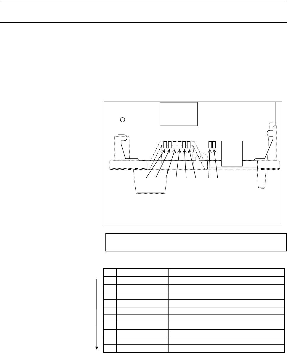
1.2.2 LED Indications
The 16i/18i/21i-A Stand-alone Ethernet board has the following LEDs:
Four green STATUS LEDs and one red ALARM LED for indicating
the status. Two green LEDs and one red LED for indicating the
communication status. The figure below shows the locations of these
LEDs. The table below explains the LED lighting states.
In the following explanations, the LED lighting states are expressed as
follows:
o: Off n: On ¶: Blinking à: Don't care
NOTE
The dashed lines indicate the faceplate.
LED lighting sequence at power on
No. LED indication Ethernet board state
1 STATUS oooo Power off
2 STATUS nnnn Initial state after power on
3 STATUS nnno MPU initialized.
4 STATUS nnoo Firmware downloaded.
5 STATUS nooo Control migration to OS
6 STATUS onnn OS PHASE1
7 STATUS onno OS PHASE2
8 STATUS onon OS PHASE3
9 STATUS onoo OS PHASE4
10 STATUS ooo¶ Startup completed.
The system enters No.10 status when the Ethernet board starts up
normally. This status is maintained until an error occurs.
CD38L
4(STASUS)(GREEN)
3(STATUS)(GREEN)
2(STATUS)(GREEN)
1(STATUS)(GREEN)
B(PAR)(RED)
6(RX)(GREEN)
5(TX)(GREEN)
A
(COL)(RED)
Contents Summary of Ethernet/Data Server Board Operators manual
- Page 1GE Fanuc Automation Europe Computer Numerical Controls Ethernet Board Data Server Board Operator’s Manual B-63354 EN / 04 TECHNOLOGY AND MORE
- Page 2- No part of this manual may be reproduced in any form. - All specifications and designs are subject to change without notice. The export of this product is subject to the authorization of the government of the country from where the product is exported. In this manual we have tried as much as possi
- Page 3B-63354EN/04 SAFETY PRECAUTIONS SAFETY PRECAUTIONS This manual includes safety precautions for protecting the user and preventing damage to the machine. Precautions are classified into Warnings and Cautions according to their bearing on safety. Also, supplementary information is described as Notes.
- Page 4SAFETY PRECAUTIONS B-63354EN/04 1.1 GENERAL WARNINGS AND CAUTIONS WARNING 1 Before operating the machine, thoroughly check the entered data. Operating the machine with incorrectly specified data may result in the machine behaving unexpectedly, possibly causing damage to the workpiece and/or machine
- Page 5B-63354EN/04 SAFETY PRECAUTIONS CAUTION 1 Immediately after switching on the power, do not touch any of the keys on the MDI panel until the position display or alarm screen appears on the CNC unit. Some of the keys on the MDI panel are dedicated to maintenance or other special operations. Pressing a
- Page 6
- Page 7B-63354EN/04 TABLE OF CONTENTS TABLE OF CONTENTS I. GENERAL 1 GENERAL ..............................................................................................3 1.1 ORGANIZATION............................................................................................4 1.2 APPLICABLE MODELS...
- Page 8TABLE OF CONTENTS B-63354EN/04 3.2 ETHERNET PARAMETER SCREEN ..........................................................47 3.3 PARAMETERS ............................................................................................52 3.4 CONFIGURING A SMALL-SCALE NETWORK ..............................
- Page 9B-63354EN/04 TABLE OF CONTENTS 4.1 RULES GOVERNING THE USE OF THE DATA SERVER FUNCTIONS .114 4.1.1 Data Server Modes .............................................................................................. 114 4.1.2 Differences Between a File Number, O Number, and File Name ...................
- Page 10TABLE OF CONTENTS B-63354EN/04 4.8.3 Inputting Tool Offsets ......................................................................................... 176 4.8.4 Outputting Tool Offsets....................................................................................... 177 4.8.5 Inputting Custom Ma
- Page 11B-63354EN/04 TABLE OF CONTENTS 6.2.1 Displaying a List of Hard Disk Files ................................................................... 225 6.2.2 Searching for a Hard Disk File ............................................................................ 226 6.2.3 Deleting a Hard Disk File.....
- Page 12TABLE OF CONTENTS B-63354EN/04 6.9.2 Changing the Connected Host ............................................................................. 278 6.10 FTP SERVER FUNCTIONS ......................................................................279 6.11 DATA SERVER (MAINTENANCE) SCREEN ...............
- Page 13B-63354EN/04 TABLE OF CONTENTS 4.3 10BASE-T CONNECTOR (CD38) PIN ASSIGNMENTS ...........................327 4.4 TWISTED-PAIR CABLE SPECIFICATION................................................328 4.4.1 Cable Connection .................................................................................
- Page 14TABLE OF CONTENTS B-63354EN/04 APPENDIX A TROUBLESHOOTING .......................................................................371 A.1 CHECKING HUB CONNECTION ..............................................................372 A.2 CHECKING TRUNK CONNECTIONS ..........................................
- Page 15I. GENERA
- Page 16
- Page 17B-63354EN/04 I. GENERAL 1.GENERAL 1 GENERAL This part explains the organization of this manual. -3-
- Page 181.GENERAL I. GENERAL B-63354EN/04 1.1 Organization This manual consists of the following parts: SAFETY PRECAUTIONS This section describes the precautions to be observed when reading this manual. I GENERAL This section describes the chapter organization, applicable models, and related manuals. II SPE
- Page 19B-63354EN/04 I. GENERAL 1.GENERAL 1.2 Applicable Models This Operator's Manual covers the following models. The abbreviations in the following table are sometimes used in text descriptions. Product name Abbreviations FANUC Series 15i-MA 15i-MA Series 15i-A 15i FANUC Series 16i-TA 16i-TA Series 16i-A
- Page 201.GENERAL I. GENERAL B-63354EN/04 1.3 Related Manuals The table below lists manuals related to this Operator's Manual. Refer to these manuals when you use this Operator's Manual. Series 15i-MA related manuals Manual name Specification number DESCRIPTIONS B-63322EN CONNECTION MANUAL (hardware) B-6332
- Page 21B-63354EN/04 I. GENERAL 1.GENERAL Series 21i-TA/MA related manuals Manual name Specification number DESCRIPTIONS B-63522EN CONNECTION MANUAL (hardware) B-63523EN CONNECTION MANUAL (function) B-63523EN-1 OPERATOR'S MANUAL (for lathe) B-63604EN OPERATOR'S MANUAL (for machining center) B-63614EN MAINTE
- Page 22
- Page 23II. SPECIFICATIO
- Page 24
- Page 25B-63354EN/04 II. SPECIFICATION 1.ETHERNET FUNCTIONS 1 Function lists ETHERNET FUNCTIONS The Ethernet board can use the following functions: Function name Applicable model FACTOLINK function Series 16i/18i/21i-A Series 16i/18i/21i-A DNC1/Ethernet function Power Mate i Series 16i/18i/21i-A FOCAS1/Ethe
- Page 261.ETHERNET FUNCTIONS II. SPECIFICATION B-63354EN/04 1.1 FACTOLINK Function The FACTOLINK function displays a work instruction on the CNC screen or transfers NC data, using the NC. For details, refer to "FANUC FACTOLINK Script Function, OPERATOR'S MANUAL (B-75054EN)." Screen display You can display a
- Page 27B-63354EN/04 II. SPECIFICATION 1.ETHERNET FUNCTIONS 1.2 DNC1/Ethernet Function The DNC1/Ethernet function enables the remote control and monitoring of the CNC from a personal computer. For details, refer to "FANUC FA SYSTEM for PC WindowsNT Version, OPERATOR'S MANUAL (B-75044EN)." NC data transfer T
- Page 281.ETHERNET FUNCTIONS II. SPECIFICATION B-63354EN/04 1.3 FOCAS1/Ethernet Function The FOCAS1/Ethernet function enables the remote control and monitoring of the CNC from a personal computer. For details, refer to "FANUC Open CNC FOCAS1/Ethernet CNC/PMC Data Window Library." NC data transfer The follow
- Page 29B-63354EN/04 II. SPECIFICATION 1.ETHERNET FUNCTIONS Operation The following operation can be controlled remotely using a personal computer: • DNC operation - 15 -
- Page 301.ETHERNET FUNCTIONS II. SPECIFICATION B-63354EN/04 1.4 Data Server Function The data server function uses FTP to transfer NC data or operate the DNC. This function is mainly used as an FTP client, but is also used as an FTP server. This function uses a hard disk or ATA flash card (hard disk) mounte
- Page 31B-63354EN/04 II. SPECIFICATION 1.ETHERNET FUNCTIONS Operation [Hard disk on the data server board ↔ Tape memory] The following operations can be performed using the NC: • DNC operation • DNC operation by calling a subprogram (M198) Operation [Personal computer ↔ Tape memory] The following operations
- Page 321.ETHERNET FUNCTIONS II. SPECIFICATION B-63354EN/04 1.5 Difference between the FOCAS1/Ethernet Function and DNC1/Ethernet Function - 18 -
- Page 33III. SETTIN
- Page 34
- Page 35B-63354EN/04 III. SETTING 1.FACTOLINK FUNCTIONS FOR THE 16i/18i/21i 1 FACTOLINK FUNCTIONS FOR THE 16i/18i/21i This section describes the settings needed to use the FACTOLINK functions with the Series 16i/18i/21i-A/B. -21-
- Page 361.FACTOLINK FUNCTIONS FOR THE 16i/18i/21i III. SETTING B-63354EN/04 1.1 PRECAUTIONS WHEN USING THE ETHERNET BOARD FOR THE FIRST TIME CAUTION When the Ethernet board is used for the first time, consult with your company's network administrator to determine the IP addresses and other settings. Then, c
- Page 37B-63354EN/04 III. SETTING 1.FACTOLINK FUNCTIONS FOR THE 16i/18i/21i 1.2 ETHERNET PARAMETER SCREEN The Ethernet Parameter screen is used to set the parameters that are needed to use the FACTOLINK functions. Display Procedure 1 Place the CNC in MDI mode. 2 Press function key SYSTEM . 3 Press the Conti
- Page 381.FACTOLINK FUNCTIONS FOR THE 16i/18i/21i III. SETTING B-63354EN/04 -24-
- Page 39B-63354EN/04 III. SETTING 1.FACTOLINK FUNCTIONS FOR THE 16i/18i/21i Display items and setting items Display items related to Ethernet functions Those items related to Ethernet functions are displayed. Item Description MAC ADDRESS MAC address of the Ethernet board NUMBER OF Total number of Ethernet e
- Page 401.FACTOLINK FUNCTIONS FOR THE 16i/18i/21i III. SETTING B-63354EN/04 Item Description IP ADDRESS 3 Specifies the IP address of the personal computer to be accessed by the FACTOLINK functions. (Format: "192.168.0.103") PORT NUMBER 3 Specifies the port No. to be used by the FACTOLINK functions within a
- Page 41B-63354EN/04 III. SETTING 1.FACTOLINK FUNCTIONS FOR THE 16i/18i/21i Entering data The following describes the basic method for entering data. Procedure 1 Place the CNC in MDI mode. 2 Display the "Ethernet Parameter" screen. 3 Position the cursor to the desired item by using the cursor movement keys.
- Page 421.FACTOLINK FUNCTIONS FOR THE 16i/18i/21i III. SETTING B-63354EN/04 (b) Enter "192.168.0.1" using the MDI keys. (c) Press soft key [INPUT] or function key INPUT to fix the data. This causes the parameters to be saved to the non-volatile memory of the CNC. -28-
- Page 43B-63354EN/04 III. SETTING 1.FACTOLINK FUNCTIONS FOR THE 16i/18i/21i 1.3 PARAMETERS The following describes the parameters related to the FACTOLINK functions. Parameters 0802 Communication channel [Data type] Byte [Valid data range] 11 to 13 11: Selects IP address 1. 12: Selects IP address 2. 13. Sel
- Page 441.FACTOLINK FUNCTIONS FOR THE 16i/18i/21i III. SETTING B-63354EN/04 0813 Length of logging data [Data type] Word [Unit of data] Number of bytes [Valid data range] 0 to 65535 Sets the length of the logging data. 0814 Logging trigger PMC address [Data type] Word [Valid data range] 0 to 65535 Sets the
- Page 45B-63354EN/04 III. SETTING 1.FACTOLINK FUNCTIONS FOR THE 16i/18i/21i 1.4 CONFIGURING A SMALL-SCALE NETWORK The following shows an example of the minimum settings needed to run the FACTOLINK functions on a small-scale network. These settings allow a personal computer to be connected to two CNCs, using
- Page 461.FACTOLINK FUNCTIONS FOR THE 16i/18i/21i III. SETTING B-63354EN/04 No.1 CNC No.2 CNC IP address 192.168.0.1 192.168.0.2 Subnet mask 255.255.255.0 255.255.255.0 Router IP address None None IP address 1 192.168.0.101 192.168.0.101 Port No.1 9000 9000 Set these items in the IP address 2 None None “Eth
- Page 47B-63354EN/04 III. SETTING 1.FACTOLINK FUNCTIONS FOR THE 16i/18i/21i 1.5 CONFIGURING A LARGE-SCALE NETWORK Before you configure a large-scale network or add such a network to an existing network, consult with your company's network administrator to determine IP addresses, subnet masks, and router IP
- Page 482.DNC1/ETHERNET FUNCTIONS FOR THE 16i/18i/21i/PMi III. SETTING B-63354EN/04 2 DNC1/ETHERNET FUNCTIONS FOR THE 16ii/18ii/21ii/PMii The following describes the settings needed to use the DNC1/Ethernet functions with the Series 16i/18i/21i-A/B and Power Mate i. -34-
- Page 49B-63354EN/04 III. SETTING 2.DNC1/ETHERNET FUNCTIONS FOR THE 16i/18i/21i/PMi 2.1 PRECAUTIONS WHEN USING THE DNC1/ETHERNET FOR THE FIRST TIME CAUTION When the Ethernet board is used for the first time, consult with your company’s network administrator to determine the IP addresses and other settings.
- Page 502.DNC1/ETHERNET FUNCTIONS FOR THE 16i/18i/21i/PMi III. SETTING B-63354EN/04 2.2 ETHERNET PARAMETER SCREEN The Ethernet Parameter screen is used to set the parameters that are needed to use the DNC1/Ethernet functions. Display Procedure 1 Place the CNC in MDI mode. 2 Press function key SYSTEM . 3 Pre
- Page 51B-63354EN/04 III. SETTING 2.DNC1/ETHERNET FUNCTIONS FOR THE 16i/18i/21i/PMi -37-
- Page 522.DNC1/ETHERNET FUNCTIONS FOR THE 16i/18i/21i/PMi III. SETTING B-63354EN/04 Display items and setting items Display items related to the Ethernet functions The items related to the Ethernet functions are displayed. Item Description MAC ADDRESS MAC address of the Ethernet board NUMBER OF Total number
- Page 53B-63354EN/04 III. SETTING 2.DNC1/ETHERNET FUNCTIONS FOR THE 16i/18i/21i/PMi NOTE 1 When the "TCP/IP setting items for the CNC" have been changed, the power must be turned off then on again. 2 The value set for "TIME INTERVAL," described under "DNC1/Ethernet setting items," may cause the communicatio
- Page 542.DNC1/ETHERNET FUNCTIONS FOR THE 16i/18i/21i/PMi III. SETTING B-63354EN/04 Entering data The following describes the basic method for entering data. Procedure 1 Place the CNC in MDI mode. 2 Display the "Ethernet Parameter" screen. 3 Position the cursor to the desired item using the cursor movement
- Page 55B-63354EN/04 III. SETTING 2.DNC1/ETHERNET FUNCTIONS FOR THE 16i/18i/21i/PMi (b) Enter "192.168.0.1" using the MDI keys. (c) Press soft key [INPUT] or function key INPUT to fix the data. This causes the parameter to be saved into the non-volatile memory of the CNC. -41-
- Page 562.DNC1/ETHERNET FUNCTIONS FOR THE 16i/18i/21i/PMi III. SETTING B-63354EN/04 2.3 PARAMETERS The following describes the parameter related to the DNC1/Ethernet functions. Parameter 0020 I/O CHANNEL: Selects the I/O device. [Data type] Byte [Valid data range] 0 to 35 6: Selects DNC1/Ethernet for the I/
- Page 57B-63354EN/04 III. SETTING 2.DNC1/ETHERNET FUNCTIONS FOR THE 16i/18i/21i/PMi 2.4 CONFIGURING A SMALL-SCALE NETWORK The following shows an example of the minimum settings needed to use the DNC1/Ethernet functions with a small-scale network. These settings allow a personal computer to be connected to t
- Page 582.DNC1/ETHERNET FUNCTIONS FOR THE 16i/18i/21i/PMi III. SETTING B-63354EN/04 2.5 CONFIGURING A LARGE-SCALE NETWORK Before you configure a large-scale network or add such a network to an existing network, consult with your company's network administrator to determine IP addresses, subnet masks, and ro
- Page 59B-63354EN/04 III. SETTING 3.FOCAS1/ETHERNET FUNCTIONS FOR THE 16i/18i/21i/PMi 3 FOCAS1/ETHERNET FUNCTIONS FOR THE 16i/18i/21i/PMi The following describes the settings needed to run the FOCAS1/Ethernet functions for the Series 16i/18i/21i-A/B and Power Mate i. -45-
- Page 603.FOCAS1/ETHERNET FUNCTIONS FOR THE 16i/18i/21i/PMi III. SETTING B-63354EN/04 3.1 PRECAUTIONS TO BE OBSERVED WHEN USING THE FOCAS1/ETHERNET FUNCTIONS FOR THE FIRST TIME CAUTION When the Ethernet board is used for the first time, consult with your company's network administrator to determine the IP a
- Page 61B-63354EN/04 III. SETTING 3.FOCAS1/ETHERNET FUNCTIONS FOR THE 16i/18i/21i/PMi 3.2 ETHERNET PARAMETER SCREEN The Ethernet Parameter screen is used to set parameters that are needed to run the FOCAS1/Ethernet functions. Display Procedure 1 Place the CNC in MDI mode. 2 Press function key SYSTEM . 3 Pre
- Page 623.FOCAS1/ETHERNET FUNCTIONS FOR THE 16i/18i/21i/PMi III. SETTING B-63354EN/04 -48-
- Page 63B-63354EN/04 III. SETTING 3.FOCAS1/ETHERNET FUNCTIONS FOR THE 16i/18i/21i/PMi Display items and setting items Display items related to the Ethernet functions The items related to the Ethernet functions are displayed. Item Description MAC ADDRESS MAC address of the Ethernet board NUMBER OF Total numb
- Page 643.FOCAS1/ETHERNET FUNCTIONS FOR THE 16i/18i/21i/PMi III. SETTING B-63354EN/04 Entering data The following describes the basic method for entering data. Procedure 1 Place the CNC in MDI mode. 2 Display the "Ethernet Parameter" screen. 3 Position the cursor to the desired item by using the cursor move
- Page 65B-63354EN/04 III. SETTING 3.FOCAS1/ETHERNET FUNCTIONS FOR THE 16i/18i/21i/PMi (b) Enter "192.168.0.1" using the MDI keys. (c) Press soft key [INPUT] or function key INPUT to fix the data. This causes the parameter to be saved into the non-volatile memory of the CNC. -51-
- Page 663.FOCAS1/ETHERNET FUNCTIONS FOR THE 16i/18i/21i/PMi III. SETTING B-63354EN/04 3.3 PARAMETERS The following describes the parameters related to the FOCAS1/Ethernet functions. Parameters 0020 I/O CHANNEL: Selects I/O device. [Data type] Byte [Unit of data] Bytes [Valid data range] 0 to 35 6: Selects F
- Page 67B-63354EN/04 III. SETTING 3.FOCAS1/ETHERNET FUNCTIONS FOR THE 16i/18i/21i/PMi 3.4 CONFIGURING A SMALL-SCALE NETWORK The following shows an example of the minimum settings needed to run the FOCAS1/Ethernet functions on a small-scale network. These settings allow a personal computer to be connected to
- Page 683.FOCAS1/ETHERNET FUNCTIONS FOR THE 16i/18i/21i/PMi III. SETTING B-63354EN/04 3.5 CONFIGURING A LARGE-SCALE NETWORK Before you configure a large-scale network or add such a network to an existing network, consult your company's network administrator to determine IP addresses, subnet masks, and route
- Page 69B-63354EN/04 III. SETTING 4.DATA SERVER FUNCTIONS FOR THE 16i/18i/21i 4 DATA SERVER FUNCTIONS FOR THE 16i/18i/21i The following describes the settings needed to run the data server functions for the Series 16i/18i/21i–A/B. -55-
- Page 704.DATA SERVER FUNCTIONS FOR THE 16i/18i/21i III. SETTING B-63354EN/04 4.1 PRECAUTIONS TO BE OBSERVED WHEN USING THE DATA SERVER FUNCTIONS FOR THE FIRST TIME CAUTION 1 When the data server board is used for the first time, format the hard disk, set the appropriate parameters, and turn the power off t
- Page 71B-63354EN/04 III. SETTING 4.DATA SERVER FUNCTIONS FOR THE 16i/18i/21i NOTE 1 One of the following option functions is needed when the data server functions are used: Series16i-TA A02B-0236-S737 Series 16i-MA A02B-0237-S737 Series 18i-TA A02B-0238-S737 Series 18i-MA A02B-0239-S737 Series 21i-TA A02B-
- Page 724.DATA SERVER FUNCTIONS FOR THE 16i/18i/21i III. SETTING B-63354EN/04 4.2 ETHERNET PARAMETER SCREEN The Ethernet Parameter screen is used to set the parameters that are needed for the data server functions. Display Procedure 1 Place the CNC in MDI mode. 2 Press function key SYSTEM . 3 Press the Cont
- Page 73B-63354EN/04 III. SETTING 4.DATA SERVER FUNCTIONS FOR THE 16i/18i/21i -59-
- Page 744.DATA SERVER FUNCTIONS FOR THE 16i/18i/21i III. SETTING B-63354EN/04 Display items and setting items Display items related to the Ethernet functions The items related to the Ethernet functions are displayed. Item Description MAC ADDRESS MAC address of the Ethernet board NUMBER OF Total number of Et
- Page 75B-63354EN/04 III. SETTING 4.DATA SERVER FUNCTIONS FOR THE 16i/18i/21i Setting items for connected host 1, host 2, and host 3 Set the items related to the host computer on which the FTP server runs. Item Description PORT NUMBER Specifies the port No. to be used by the data server functions. Usually,
- Page 764.DATA SERVER FUNCTIONS FOR THE 16i/18i/21i III. SETTING B-63354EN/04 NOTE 1 When the "TCP/IP setting items for the CNC" have been changed, the power must be turned off then on again. 2 Note that the system differentiates between upper- and lower-case characters in "USERNAME" and "PASSWORD," describ
- Page 77B-63354EN/04 III. SETTING 4.DATA SERVER FUNCTIONS FOR THE 16i/18i/21i Entering data The following describes the basic method for entering data. Procedure 1 Place the CNC in MDI mode. 2 Display the "Ethernet Parameter" screen. 3 Position the cursor to the desired item by using the cursor movement key
- Page 784.DATA SERVER FUNCTIONS FOR THE 16i/18i/21i III. SETTING B-63354EN/04 (b) Enter "192.168.0.1" using the MDI keys. (c) Press soft key [INPUT] or function key INPUT to fix the data. This causes the parameter to be saved into the non-volatile memory of the CNC. -64-
- Page 79B-63354EN/04 III. SETTING 4.DATA SERVER FUNCTIONS FOR THE 16i/18i/21i Entering lowercase characters The following describes the method for entering lowercase characters. Procedure 1 Place the CNC in MDI mode. 2 Display the "Ethernet Parameter" screen. 3 Position the cursor to the desired item by usi
- Page 804.DATA SERVER FUNCTIONS FOR THE 16i/18i/21i III. SETTING B-63354EN/04 Entering long character strings The following describes the method for entering long character strings. In the following explanation, the string "/DATASERVER/NCPROGRAM/LINE001/GROUP0002" is entered as an example. Procedure 1 Place
- Page 81B-63354EN/04 III. SETTING 4.DATA SERVER FUNCTIONS FOR THE 16i/18i/21i 4 Press soft key [STRING]. The cursor position and soft key menu change as follows. 5 Enter "/DATASERVER/NCPROGRAM/LINE001/GR" using the MDI keys and then press soft key [INPUT]. -67-
- Page 824.DATA SERVER FUNCTIONS FOR THE 16i/18i/21i III. SETTING B-63354EN/04 6. Enter the subsequent part of the string, "OUP0002," using the MDI keys and then press soft key [INPUT]. [Reference] The character string can also be entered as different parts such as "/DATASERVER/NCPROGRAM" and "/LINE001/GROUP
- Page 83B-63354EN/04 III. SETTING 4.DATA SERVER FUNCTIONS FOR THE 16i/18i/21i 7 To insert "FACTORY0010" between "NCPROGRAM" and "LINE001," position the cursor to the "/" before "LINE001" and enter "/FACTORY0010" using the MDI keys. Then, press soft key [INSERT]. 8 To delete a character, position the cursor
- Page 844.DATA SERVER FUNCTIONS FOR THE 16i/18i/21i III. SETTING B-63354EN/04 10 Upon the completion of character string entry, press soft key [EXIT]. This operation returns the cursor and the soft key menu to the state shown under "Procedure 1." The data is saved into the non-volatile memory of the CNC. -7
- Page 85B-63354EN/04 III. SETTING 4.DATA SERVER FUNCTIONS FOR THE 16i/18i/21i Entering special characters The following describes the method for entering special characters. In the following explanation, the string "PROG$" is entered as an example. Procedure 1 Place the CNC in MDI mode. 2 Display the "Ether
- Page 864.DATA SERVER FUNCTIONS FOR THE 16i/18i/21i III. SETTING B-63354EN/04 5 Press soft key [$]. 6 Press soft key [INPUT]. -72-
- Page 87B-63354EN/04 III. SETTING 4.DATA SERVER FUNCTIONS FOR THE 16i/18i/21i 4.3 PARAMETERS The following describes the parameters related to the data server functions. Parameters 0020 I/O CHANNEL: Selects an I/O device. [Data type] Byte [Valid data range] 0 to 35 5: Selects the data server for the I/O dev
- Page 884.DATA SERVER FUNCTIONS FOR THE 16i/18i/21i III. SETTING B-63354EN/04 924 DNC1/Ethernet or FOCAS1/Ethernet wait time [Data type] Byte [Unit of data] ms [Valid data range] 0 to 255 Specifies the wait time (in ms units) for the DNC1/Ethernet or FOCAS1/Ethernet service when it is used together with the
- Page 89B-63354EN/04 III. SETTING 4.DATA SERVER FUNCTIONS FOR THE 16i/18i/21i 4.4 CONFIGURING A SMALL-SCALE NETWORK The following shows an example of the minimum settings needed to use the data server functions on a small-scale network. These settings allow a personal computer to be connected to one CNC by
- Page 904.DATA SERVER FUNCTIONS FOR THE 16i/18i/21i III. SETTING B-63354EN/04 4.5 CONFIGURING A LARGE-SCALE NETWORK Before you configure a large-scale network or add such a network to an existing network, consult with your company's network administrator to determine IP addresses, subnet masks, and router I
- Page 91B-63354EN/04 III. SETTING 5.FOCAS1/ETHERNET FUNCTIONS FOR THE 15i 5 FOCAS1/ETHERNET FUNCTIONS FOR THE 15i The following describes the settings needed to run the FOCAS1/Ethernet functions for the Series 15i. -77-
- Page 925.FOCAS1/ETHERNET FUNCTIONS FOR THE 15i III. SETTING B-63354EN/04 5.1 PRECAUTIONS TO BE OBSERVED WHEN USING THE FOCAS1/ETHERNET FUNCTIONS FOR THE FIRST TIME CAUTION When the Ethernet board is used for the first time, consult with your company's network administrator to determine the IP addresses and
- Page 93B-63354EN/04 III. SETTING 5.FOCAS1/ETHERNET FUNCTIONS FOR THE 15i 5.2 ETHERNET PARAMETER SCREEN The Ethernet Parameter screen is used to set parameters that are needed to run the FOCAS1/Ethernet functions. Display Procedure 1 Place the CNC in MDI mode. 2 Press function key SYSTEM . 3 Press soft key
- Page 945.FOCAS1/ETHERNET FUNCTIONS FOR THE 15i III. SETTING B-63354EN/04 -80-
- Page 95B-63354EN/04 III. SETTING 5.FOCAS1/ETHERNET FUNCTIONS FOR THE 15i Display items and setting items Items related to the Ethernet functions The items related to the Ethernet functions are displayed. Item Description MAC ADDRESS MAC address of the data server board TCP/IP setting items for the CNC Set
- Page 965.FOCAS1/ETHERNET FUNCTIONS FOR THE 15i III. SETTING B-63354EN/04 Entering data The following describes the basic method for entering data. Procedure 1 Place the CNC in MDI mode. 2 Display the "Ethernet (Setting)" screen. 3 Position the cursor to the desired item using the cursor movement keys. 4 En
- Page 97B-63354EN/04 III. SETTING 5.FOCAS1/ETHERNET FUNCTIONS FOR THE 15i (b) Enter "192.168.0.1" using the MDI keys. (c) Press soft key [INPUT] or function key INPUT to fix the data. -83-
- Page 985.FOCAS1/ETHERNET FUNCTIONS FOR THE 15i III. SETTING B-63354EN/04 (d) Press soft key [SAVE]. (e) Press soft key [EXEC]. This saves the parameters into the non-volatile memory of the CNC. -84-
- Page 99B-63354EN/04 III. SETTING 5.FOCAS1/ETHERNET FUNCTIONS FOR THE 15i 5.3 PARAMETERS The following describes the parameters related to the FOCAS1/Ethernet functions. Parameters 0020 Interface number of input device for foreground [Input section] Setting input [Data type] Integer [Valid data range] 0 to
- Page 1005.FOCAS1/ETHERNET FUNCTIONS FOR THE 15i III. SETTING B-63354EN/04 5.4 CONFIGURING A SMALL-SCALE NETWORK The following shows an example of the minimum settings needed to run the FOCAS1/Ethernet functions on a small-scale network. These settings allow a personal computer to be connected to two CNCs by
- Page 101B-63354EN/04 III. SETTING 5.FOCAS1/ETHERNET FUNCTIONS FOR THE 15i 5.5 CONFIGURING A LARGE-SCALE NETWORK Before you configure a large-scale network or add such a network to an existing network, consult your company's network administrator to determine IP addresses, subnet masks, and router IP address
- Page 1026.DATA SERVER FUNCTIONS FOR THE 15i III. SETTING B-63354EN/04 6 DATA SERVER FUNCTIONS FOR THE 15i The following describes the settings needed to use the data server functions with the Series 15i-A. -88-
- Page 103B-63354EN/04 III. SETTING 6.DATA SERVER FUNCTIONS FOR THE 15i 6.1 PRECAUTIONS TO BE OBSERVED WHEN USING THE DATA SERVER FUNCTIONS FOR THE FIRST TIME CAUTION 1 When the data server board is used for the first time, format the hard disk, set the appropriate parameters, and turn the power off then on a
- Page 1046.DATA SERVER FUNCTIONS FOR THE 15i III. SETTING B-63354EN/04 6.2 ETHERNET PARAMETER SCREEN The Ethernet Parameter screen is used to set the parameters needed for the data server functions. Display Procedure 1 Place the CNC in MDI mode. 2 Press function key SYSTEM . 3 Press soft key [CHAPTER]. 4 Whe
- Page 105B-63354EN/04 III. SETTING 6.DATA SERVER FUNCTIONS FOR THE 15i NOTE If the CNC software series is the F001 or F601, the setting cannot be performed for host 2 or 3. -91-
- Page 1066.DATA SERVER FUNCTIONS FOR THE 15i III. SETTING B-63354EN/04 Display items and setting items Items related to the Ethernet functions The items related to the Ethernet functions are displayed. Item Description MAC ADDRESS MAC address of the data server board TCP/IP setting items for the CNC Set the
- Page 107B-63354EN/04 III. SETTING 6.DATA SERVER FUNCTIONS FOR THE 15i NOTE 1 When the "TCP/IP setting items for the CNC" have been changed, the power must be turned off then on again. 2 Note that the system differentiates between upper- and lower-case characters in "USERNAME" and "PASSWORD," described under
- Page 1086.DATA SERVER FUNCTIONS FOR THE 15i III. SETTING B-63354EN/04 Entering data The following describes the basic method for entering data. Procedure 1 Place the CNC in MDI mode. 2 Display the "Ethernet (Setting)" screen. 3 Position the cursor to the desired item using the cursor movement keys. 4 Enter
- Page 109B-63354EN/04 III. SETTING 6.DATA SERVER FUNCTIONS FOR THE 15i (b) Enter "192.168.0.1" using the MDI keys. (c) Press soft key [INPUT] or function key INPUT to fix the data. -95-
- Page 1106.DATA SERVER FUNCTIONS FOR THE 15i III. SETTING B-63354EN/04 (d) Press soft key [SAVE]. (e) Press soft key [EXEC]. This saves the parameters into the non-volatile memory of the CNC. -96-
- Page 111B-63354EN/04 III. SETTING 6.DATA SERVER FUNCTIONS FOR THE 15i 6.3 PARAMETERS The following describes the parameters related to the data server functions. Parameters 0020 Interface number of input device for foreground [Input section] Setting input [Data type] Integer [Valid data range] 0 to 16 14: S
- Page 1126.DATA SERVER FUNCTIONS FOR THE 15i III. SETTING B-63354EN/04 5030 Selects host 3 OS. [Input section] Parameter input [Data type] Integer [Valid data range] 0 and 1 1: UNIX/VMS. 0: Windows 95/98/NT. #7 #6 #5 #4 #3 #2 #1 #0 5038 LCK BWT [Input section] Parameter input [Data type] Bit LCK Specifies wh
- Page 113B-63354EN/04 III. SETTING 6.DATA SERVER FUNCTIONS FOR THE 15i 6.4 CONFIGURING A SMALL-SCALE NETWORK The following shows an example of the minimum settings needed to use the data server functions on a small-scale network. These settings allow a personal computer to be connected to one CNC by the data
- Page 1146.DATA SERVER FUNCTIONS FOR THE 15i III. SETTING B-63354EN/04 6.5 CONFIGURING A LARGE-SCALE NETWORK Before you configure a large-scale network or add such a network to an existing network, consult with your company's network administrator to determine IP addresses, subnet masks, and router IP addres
- Page 115IV. OPERATIO
- Page 116
- Page 117B-63354EN/04 IV. OPERATION 1.16i/18i/21i FACTOLINK FUNCTIONS 1 16i/18i/21i FACTOLINK FUNCTIONS This section describes how to use the series 16i/18i/21i-A/B FACTOLINK functions. -103-
- Page 1181.16i/18i/21i FACTOLINK FUNCTIONS IV. OPERATION B-63354EN/04 1.1 FACTOLINK SCREEN Display Procedure 1 Press function key MESSAGE . 2 Press the continuation menu key at the right end of the soft key menu. 3 When you press soft key [FALINK], the FACTOLINK screen appears. The following is a sample FACT
- Page 119B-63354EN/04 IV. OPERATION 1.16i/18i/21i FACTOLINK FUNCTIONS 1.2 ETHERNET ERROR MESSAGE SCREEN If an error related to the FACTOLINK functions occurs, an error message appears on the error message screen dedicated to the Ethernet functions. Display Procedure 1 Press function key MESSAGE . 2 Press the
- Page 1201.16i/18i/21i FACTOLINK FUNCTIONS IV. OPERATION B-63354EN/04 Configuration The following titles are provided for the Ethernet error message screen: • SYSTEM ERROR screen • TCP/IP STACK ERROR screen • PARAMETER ERROR screen • FACTOLINK #1 MESSAGE screen • FACTOLINK #2 MESSAGE screen • FACTOLINK #3 ME
- Page 121B-63354EN/04 IV. OPERATION 2.16i/18i/21i/PMi DNC1/Ethernet FUNCTIONS 2 16i/18i/21i/PMi DNC1/Ethernet FUNCTIONS This section describes how to use the Series 16i/18i/21i-A/B, Power Mate i , DNC1/Ethernet functions. -107-
- Page 1222.16i/18i/21i/PMi DNC1/Ethernet FUNCTIONS IV. OPERATION B-63354EN/04 2.1 ETHERNET ERROR MESSAGE SCREEN If an error related to the DNC1/Ethernet functions occurs, an error message appears on the error message screen dedicated to the Ethernet functions. Display Procedure 1 Press function key MESSAGE .
- Page 123B-63354EN/04 IV. OPERATION 2.16i/18i/21i/PMi DNC1/Ethernet FUNCTIONS Configuration The following titles are provided for the Ethernet error message screen: • SYSTEM ERROR screen • TCP/IP STACK ERROR screen • PARAMETER ERROR screen • DNC1/ETH FOCAS1/ETH C0 screen • DNC1/ETH FOCAS1/ETH C1 screen • DNC
- Page 1243.16i/18i/21i/PMi FOCAS1/Ethernet FUNCTIONS IV. OPERATION B-63354EN/04 3 16i/18i/21i/PMi FOCAS1/Ethernet FUNCTIONS This section describes how to use the Series 16i/18i/21i-A/B and Power Mate i FOCAS1/Ethernet functions. -110-
- Page 125B-63354EN/04 IV. OPERATION 3.16i/18i/21i/PMi FOCAS1/Ethernet FUNCTIONS 3.1 ETHERNET ERROR MESSAGE SCREEN If an error occurs for the FOCAS1/Ethernet functions, an error message is displayed on the error message screen dedicated to the Ethernet functions. Display Procedure 1 Press function key MESSAGE
- Page 1263.16i/18i/21i/PMi FOCAS1/Ethernet FUNCTIONS IV. OPERATION B-63354EN/04 Configuration The following titles are provided for the Ethernet error message screen: • SYSTEM ERROR screen • TCP/IP STACK ERROR screen • PARAMETER ERROR screen • DNC1/ETH FOCAS1/ETH C0 screen • DNC1/ETH FOCAS1/ETH C1 screen • D
- Page 127B-63354EN/04 IV. OPERATION 4.16i/18i DATA SERVER FUNCTIONS 4 16i/18i/21i DATA SERVER FUNCTIONS This section describes how to use the series 16i/18i/21i-A/B data server functions. -113-
- Page 1284.16i/18i DATA SERVER FUNCTIONS IV. OPERATION B-63354EN/04 4.1 RULES GOVERNING THE USE OF THE DATA SERVER FUNCTIONS This section describes the rules governing the use of the data server functions. 4.1.1 Data Server Modes The data server function can run in three modes when it transfers NC data (such
- Page 129B-63354EN/04 IV. OPERATION 4.16i/18i DATA SERVER FUNCTIONS FTP mode In the FTP mode, data is transferred between the host computer built-in hard disk and CNC part program storage. For example, DNC operations including a DNC operation by a subprogram call (M198) require that the related NC programs b
- Page 1304.16i/18i DATA SERVER FUNCTIONS IV. OPERATION B-63354EN/04 Buffer mode In the buffer mode, an NC program that is larger than the capacity of the data server board built-in hard disk can run more safely than in the FTP mode. To be specific, if an NC program that is too large to fit on the data server
- Page 131B-63354EN/04 IV. OPERATION 4.16i/18i DATA SERVER FUNCTIONS 4.1.2 Differences Between a File Number, O Number, and File Name This subsection explains the differentiation between a file number, O number, and file name described in this manual. • File number Used to identify a file (data) stored in the
- Page 1324.16i/18i DATA SERVER FUNCTIONS IV. OPERATION B-63354EN/04 4.1.4 Differences Between a Hard Disk File and Host File This subsection explains the differentiation between a hard disk file and host file described in this manual. • Hard disk file Stored on the hard disk of the CNC data server board (her
- Page 133B-63354EN/04 IV. OPERATION 4.16i/18i DATA SERVER FUNCTIONS 4.1.5 Hard Disk File Names The name of any file on the data server board built-in hard disk is represented using the 8.3 file name format (8 characters in the file name and 3 characters in the file name extension) originally adopted for MS-D
- Page 1344.16i/18i DATA SERVER FUNCTIONS IV. OPERATION B-63354EN/04 4.1.6 NC Program Format The NC program prepared by the host computer must conform to the format shown below. % TITLE ; O0001(COMMENT) ; . . . M30 ; % The NC program begins with % (start file mark). A comment (title, etc.) can be inserted, as
- Page 135B-63354EN/04 IV. OPERATION 4.16i/18i DATA SERVER FUNCTIONS 4.1.7 List File Formats Use one of the following list formats for the LIST-GET, LIST-PUT, and LIST-DELETE functions, which are described later. Format 1 % ; O0001(COMMENT) ; N111 ; N222 ; N333 ; : : N999 ; % Format 2 % ; O0001(COMMENT) ; N11
- Page 1364.16i/18i DATA SERVER FUNCTIONS IV. OPERATION B-63354EN/04 Specifications common to all formats <1> The list file begins with "%" (start file mark). <2> An O number must be specified in the next block. The list file must be named using the same O number. A comment enclosed in parentheses "(" and ")"
- Page 137B-63354EN/04 IV. OPERATION 4.16i/18i DATA SERVER FUNCTIONS Specifications of format 3 The specifications of the format-3 list files are as follows: <1> In this format, process files have an arbitrary name. It is assumed that each file has the same name when it is on the data server board built-in ha
- Page 1384.16i/18i DATA SERVER FUNCTIONS IV. OPERATION B-63354EN/04 Restrictions on file names in the list file The following restrictions apply when file names are specified in the list file. <1> Only the following 76 different ASCII characters can be used in arbitrary file names. Digits 0 to 9 Lowercase le
- Page 139B-63354EN/04 IV. OPERATION 4.16i/18i DATA SERVER FUNCTIONS List file storage location The LIST-GET, LIST-PUT, and LIST-DELETE services are useful to manage more than one NC program in a group. The storage location for the list file varies depending on what service is to be executed. If the LIST-GET
- Page 1404.16i/18i DATA SERVER FUNCTIONS IV. OPERATION B-63354EN/04 4.1.8 Buffer Mode Specifications The buffer mode is designed to handle NC programs larger than the capacity of the data server board built-in hard disk. In this mode, the data server board built-in hard disk is used as a temporary, intermedi
- Page 141B-63354EN/04 IV. OPERATION 4.16i/18i DATA SERVER FUNCTIONS 4.1.8.1 How to use the buffer mode The buffer mode is designed to handle an NC program larger than the capacity of the data server board built-in hard disk. This mode can be used with DNC operations (Section 4.6) including a DNC operation by
- Page 1424.16i/18i DATA SERVER FUNCTIONS IV. OPERATION B-63354EN/04 NOTE Even in the buffer mode, it is possible to newly register files on the data server board built-in hard disk, using operations such as "NC program GET" and "output to NC program." These operations, however, may cause a buffer mode DNC op
- Page 143B-63354EN/04 IV. OPERATION 4.16i/18i DATA SERVER FUNCTIONS 4.1.8.2 How to divide an NC program into several files In buffer mode operations, the host computer must previously divide an NC program into several files and create a list of these files arranged in the sequence in which they are to be tra
- Page 1444.16i/18i DATA SERVER FUNCTIONS IV. OPERATION B-63354EN/04 NOTE 1 The size of files into which an NC program is divided should be 20 to 30 MB. If the size is very large, there will be much idle time before the DNC operation begins. If the size is very small, data may be interrupted between files, re
- Page 145B-63354EN/04 IV. OPERATION 4.16i/18i DATA SERVER FUNCTIONS 4.1.9 Data Server Screen Manipulation and Status Indication • Display during operation During operation, the status is displayed at the lower-right of the screen. • Display upon completion of the operation Upon the completion of this operati
- Page 1464.16i/18i DATA SERVER FUNCTIONS IV. OPERATION B-63354EN/04 Operation Screen Status CONECT 1, CONECT 2, Connection Host Change CONNECT CONECT3 screen FORMAT Data Server Maintenance FORMAT screen CHKDSK Data Server Maintenance HD CHECK screen INPUT Ethernet parameters screen SETTING -132-
- Page 147B-63354EN/04 IV. OPERATION 4.16i/18i DATA SERVER FUNCTIONS 4.2 HARD DISK FILE DIR SCREEN The Hard Disk File Dir screen is used to list the files on the data server board built-in hard disk. -133-
- Page 1484.16i/18i DATA SERVER FUNCTIONS IV. OPERATION B-63354EN/04 Display items • REGISTERED PROGRAMS Displays the number of files stored in the current work directory. • FREE DISK AREA Displays the amount of free space, in bytes, on the data server board built-in hard disk. • CURRENT DIRECTORY Displays th
- Page 149B-63354EN/04 IV. OPERATION 4.16i/18i DATA SERVER FUNCTIONS • PUT Transfers a single file from the data server board built-in hard disk to the host computer built-in hard disk. • MPUT Transfers two or more files from the data server board built-in hard disk to the host computer built-in hard disk. Th
- Page 1504.16i/18i DATA SERVER FUNCTIONS IV. OPERATION B-63354EN/04 4.2.1 Displaying a List of Hard Disk Files Display a list of the files stored on the data server board built-in hard disk. Procedure 1 Press function key PROG . 2 Press the continuation menu key at the right end of the soft key menu. 3 When
- Page 151B-63354EN/04 IV. OPERATION 4.16i/18i DATA SERVER FUNCTIONS 4.2.2 Searching for a Hard Disk File Display a list of the files stored on the data server board built-in hard disk by using the specified file as the first. Specify the file with the file number or name. Procedure 1 Display the Hard Disk Fi
- Page 1524.16i/18i DATA SERVER FUNCTIONS IV. OPERATION B-63354EN/04 4.2.3 Deleting a Hard Disk File Delete files stored on the data server board built-in hard disk. Deleting a single file Procedure 1 Display the Hard Disk File Dir screen. 2 Press soft key [(OPRT)]. 3 Press soft key [F DEL]. 4 Enter the numbe
- Page 153B-63354EN/04 IV. OPERATION 4.16i/18i DATA SERVER FUNCTIONS Deleting two or more files Procedure 1 Display the Hard Disk File Dir screen. 2 Press soft key [(OPRT)]. 3 Press soft key [F DEL]. 4 Enter the names of the files (including wild cards) to be deleted using the MDI keys. [Input format]
- Page 1544.16i/18i DATA SERVER FUNCTIONS IV. OPERATION B-63354EN/04 4.2.4 Copying a Hard Disk File Copy files stored in the data server board built-in hard disk. Procedure 1 Display the Hard Disk File Dir screen. 2 Press soft key [(OPRT)]. 3 Press soft key [F COPY]. 4 Enter the number or name of the copy sou
- Page 155B-63354EN/04 IV. OPERATION 4.16i/18i DATA SERVER FUNCTIONS 4.2.5 Changing a Hard Disk File Name Change the name of a file stored on the data server board built-in hard disk. Procedure 1 Display the Hard Disk File Dir screen. 2 Press soft key [(OPRT)]. 3 Press soft key [FD CHA]. 4 Enter the number or
- Page 1564.16i/18i DATA SERVER FUNCTIONS IV. OPERATION B-63354EN/04 4.2.6 Creating a Directory on the Data Server Board Built-in Hard Disk Create a directory (folder) on the data server board built-in hard disk. Procedure 1 Display the Hard Disk File Dir screen. 2 Press soft key [(OPRT)]. 3 Press the continu
- Page 157B-63354EN/04 IV. OPERATION 4.16i/18i DATA SERVER FUNCTIONS 4.2.7 Deleting a Directory from the Data Server Board Built-in Hard Disk Delete a directory (folder) from the data server board built-in hard disk. Procedure 1 Display the Hard Disk File Dir screen. 2 Press soft key [(OPRT)]. 3 Press the con
- Page 1584.16i/18i DATA SERVER FUNCTIONS IV. OPERATION B-63354EN/04 4.2.8 Moving to Another Directory on the Data Server Board Built-in Hard Disk Changes the work directory on the data server board built-in hard disk. Procedure 1 Display the Hard Disk File Dir screen. 2 Press soft key [(OPRT)]. 3 Press the c
- Page 159B-63354EN/04 IV. OPERATION 4.16i/18i DATA SERVER FUNCTIONS 4.2.9 Executing Hard Disk File PUT Using FTP, transfer files from the data server board built-in hard disk to the host computer built-in hard disk. Procedure 1 Display the Hard Disk File Dir screen. 2 Press soft key [(OPRT)]. 3 Press the con
- Page 1604.16i/18i DATA SERVER FUNCTIONS IV. OPERATION B-63354EN/04 NOTE 1 The transfer source file number or name must be separated from the transfer destination file name by a comma (,). 2 The transfer destination file name and delimiter (,) can be omitted. In such a case, the transfer destination file nam
- Page 161B-63354EN/04 IV. OPERATION 4.16i/18i DATA SERVER FUNCTIONS 4.2.10 Executing Hard Disk File MPUT Using FTP and wild cards (*, ?), transfer two or more files at one time from the data server board built-in hard disk to the host computer built-in hard disk. Procedure 1 Display the Hard Disk File Dir sc
- Page 1624.16i/18i DATA SERVER FUNCTIONS IV. OPERATION B-63354EN/04 4.2.11 Executing Hard Disk File LIST-PUT Transfer files from the data server board built-in hard disk to the host computer built-in hard disk according to the contents of the list file, using the FTP. Procedure 1 Display the Hard Disk File D
- Page 163B-63354EN/04 IV. OPERATION 4.16i/18i DATA SERVER FUNCTIONS 4.2.12 Executing Hard Disk File LIST-DELETE Delete files from the data server board built-in hard disk according to the contents of the list file. Procedure 1 Display the Hard Disk File Dir screen. 2 Press soft key [(OPRT)]. 3 Press the cont
- Page 1644.16i/18i DATA SERVER FUNCTIONS IV. OPERATION B-63354EN/04 4.3 HOST FILE DIR SCREEN The Host File Dir screen is used to display a file list for the host computer built-in hard disk. NOTE 1 A file name containing kanji, hiragana, and katakana characters is not displayed correctly. 2 The number of pro
- Page 165B-63354EN/04 IV. OPERATION 4.16i/18i DATA SERVER FUNCTIONS NOTE The above HOST FILE DIR (detail) screen is one display example. The display contents depend on the specifications of the FTP server used by the host computer. Display items • REGISTERED PROGRAMS Displays the number of files registered w
- Page 1664.16i/18i DATA SERVER FUNCTIONS IV. OPERATION B-63354EN/04 Operations • SWITCH Switches between normal display and detailed display. • UPDATE Updates the display contents. • STOP Stops the [GET], [MGET], and [L-GET] operations. • DISPLAY Updates the screen using the file specified by the file number
- Page 167B-63354EN/04 IV. OPERATION 4.16i/18i DATA SERVER FUNCTIONS 4.3.1 Displaying a List of Host Files Display a list of files stored on the host computer built-in hard disk. Procedure 1 Press function key PROG . 2 Press the continuation menu key at the right end of the soft key menu. 3 When you press sof
- Page 1684.16i/18i DATA SERVER FUNCTIONS IV. OPERATION B-63354EN/04 4.3.2 Searching for a Host File Display a list of files stored on the host computer built-in hard disk by using the file specified with the file number as the first. Procedure 1 Display the Host File Dir screen. 2 Press soft key [(OPRT)]. 3
- Page 169B-63354EN/04 IV. OPERATION 4.16i/18i DATA SERVER FUNCTIONS 4.3.3 Deleting a Host File Delete files stored on the host computer built-in hard disk. Procedure 1 Display the Host File Dir screen. 2 Press soft key [(OPRT)]. 3 Press soft key [F DEL]. 4 Enter the number or name of the file to be deleted u
- Page 1704.16i/18i DATA SERVER FUNCTIONS IV. OPERATION B-63354EN/04 4.3.4 Executing Host File GET Using FTP, transfer files from the host computer built-in hard disk to the data server board built-in hard disk. Procedure 1 Display the Host File Dir screen. 2 Press soft key [(OPRT)]. 3 Press the continuation
- Page 171B-63354EN/04 IV. OPERATION 4.16i/18i DATA SERVER FUNCTIONS NOTE 1 The number or name of a transfer source file must be separated from a transfer destination file name by a comma (,). 2 The transfer destination file name and delimiter "," can be omitted. In this case, the transfer destination file na
- Page 1724.16i/18i DATA SERVER FUNCTIONS IV. OPERATION B-63354EN/04 4.3.5 Executing Host File MGET Using wild cards (*, ?) and FTP, transfer two or more files at one time from the host computer built-in hard disk to the data server board built-in hard disk. Procedure 1 Display the Host File Dir screen. 2 Pre
- Page 173B-63354EN/04 IV. OPERATION 4.16i/18i DATA SERVER FUNCTIONS NOTE 1 Wild card interpretation depends on the host computer specifications. 2 If a work directory on the host computer built-in hard disk contains a subdirectory, and a wild card that can represent the subdirectory is used to specify a tran
- Page 1744.16i/18i DATA SERVER FUNCTIONS IV. OPERATION B-63354EN/04 4.3.6 Executing Host File LIST-GET Transfer files from the host computer built-in hard disk to the data server board built-in hard disk according to the contents of the list file, using the FTP. Procedure 1 Display the Host File Dir screen.
- Page 175B-63354EN/04 IV. OPERATION 4.16i/18i DATA SERVER FUNCTIONS 4.4 INPUTTING AN NC PROGRAM Input a file (NC program) from the data server board built-in hard disk or host computer built-in hard disk to the tape memory. For the Hard Disk File Dir screen or Host File Dir screen Procedure 1 Place the CNC i
- Page 1764.16i/18i DATA SERVER FUNCTIONS IV. OPERATION B-63354EN/04 [Example 1] Enter O0001.DAT to input file O0001.DAT from the data server board built-in hard disk to the tape memory. However, the O number to be input into tape memory depends on the O number described in file O0001.DAT. [Example 2] Enter O
- Page 177B-63354EN/04 IV. OPERATION 4.16i/18i DATA SERVER FUNCTIONS For the program screen Procedure 1 Place the CNC in EDIT mode. 2 Press function key PROG . 3 Press the continuation menu key at the right end of the soft key menu. 4 When you press soft key [PRGRM], the Program screen is displayed. 5 Press s
- Page 1784.16i/18i DATA SERVER FUNCTIONS IV. OPERATION B-63354EN/04 4.5 OUTPUTTING AN NC PROGRAM A file (NC program) is output from the tape memory to the data server board built-in hard disk or host computer built-in hard disk. For the Hard Disk File Dir screen or Host File Dir screen Procedure 1 Place the
- Page 179B-63354EN/04 IV. OPERATION 4.16i/18i DATA SERVER FUNCTIONS For the program screen Procedure 1 Place the CNC in EDIT mode. 2 Press function key PROG . 3 Press the continuation menu key at the right end of the soft key menu. 4 When you press soft key [PRGRM], the Program screen appears. 5 Press soft k
- Page 1804.16i/18i DATA SERVER FUNCTIONS IV. OPERATION B-63354EN/04 4.6 DNC OPERATIONS DNC operation is performed using an NC program stored on the data server board built-in hard disk or on the host computer built-in hard disk. For DNC operation in storage mode Procedure 1 Place the CNC in RMT mode. 2 Displ
- Page 181B-63354EN/04 IV. OPERATION 4.16i/18i DATA SERVER FUNCTIONS For DNC operation in FTP mode Procedure 1 Place the CNC in RMT mode. 2 Select the host number for the host holding a file list to be used for an DNC operation according to the procedure described in Subsection 4.9.2, "Reconnecting the Host,"
- Page 1824.16i/18i DATA SERVER FUNCTIONS IV. OPERATION B-63354EN/04 For DNC operation in buffer mode Procedure 1 Place the CNC in RMT mode. 2 Select the host number for the host holding a file list to be used for an DNC operation according to the procedure described in Subsection 4.9.2, "Reconnecting the Hos
- Page 183B-63354EN/04 IV. OPERATION 4.16i/18i DATA SERVER FUNCTIONS 4.7 DNC OPERATION BY A SUBPROGRAM CALL (M198) Format for calling a subprogram from the main program (1) For Series 15 command format M198P∆∆∆∆Lxxxx; ∆∆∆∆ : NC program number on the hard disk (4-digit numeral following O of the O number) xxxx
- Page 1844.16i/18i DATA SERVER FUNCTIONS IV. OPERATION B-63354EN/04 DNC operation by a subprogram call (M198) in the storage mode Procedure 1 Place the CNC in MEM mode. 2 Display the Hard Disk File Directory screen and move to the directory holding an NC program to be called by a subprogram. 3 Press soft key
- Page 185B-63354EN/04 IV. OPERATION 4.16i/18i DATA SERVER FUNCTIONS DNC operation by a subprogram call (M198) in the FTP mode Procedure 1 Place the CNC in MEM mode. 2 Select the host number for the host holding an NC program to be called by a subprogram according to the procedure described in Subsection 4.9.
- Page 1864.16i/18i DATA SERVER FUNCTIONS IV. OPERATION B-63354EN/04 DNC operation by a subprogram call (M198) in the buffer mode Procedure 1 Place the CNC in MEM mode. 2 Select the host number for the host holding a file list to be called by a subprogram according to the procedure described in Subsection 4.9
- Page 187B-63354EN/04 IV. OPERATION 4.16i/18i DATA SERVER FUNCTIONS 4.8 DATA INPUT/OUTPUT The data listed below can be transferred between the data server board and CNC. How to transfer the data is explained later. 1 NC parameter 2 Tool offset value 3 Custom macro value 4 Workpiece zero point offset value 5
- Page 1884.16i/18i DATA SERVER FUNCTIONS IV. OPERATION B-63354EN/04 4.8.1 Inputting the Parameter Input files (NC parameters) from the data server built-in hard disk or host computer built-in hard disk to part program storage. For the Parameter screen Procedure 1 Place the CNC in EDIT mode. 2 Press function
- Page 189B-63354EN/04 IV. OPERATION 4.16i/18i DATA SERVER FUNCTIONS 4.8.2 Outputting the Parameter Output files (NC parameters) from part program storage to the data server built-in hard disk or host computer built-in hard disk. For the Parameter screen Procedure 1 Place the CNC in EDIT mode. 2 Press functio
- Page 1904.16i/18i DATA SERVER FUNCTIONS IV. OPERATION B-63354EN/04 4.8.3 Inputting Tool Offsets A file (tool offset value) is input from the data server board built-in hard disk or host computer built-in hard disk to the part program storage memory. For the Tool Compensation screen Procedure 1 Place the CNC
- Page 191B-63354EN/04 IV. OPERATION 4.16i/18i DATA SERVER FUNCTIONS 4.8.4 Outputting Tool Offsets A file (tool offset value) is output from the tape memory to the data server board built-in hard disk or host computer built-in hard disk. For the Tool Compensation screen Procedure 1 Place the CNC in EDIT mode.
- Page 1924.16i/18i DATA SERVER FUNCTIONS IV. OPERATION B-63354EN/04 4.8.5 Inputting Custom Macro Variables A file (custom macro variables) is input from the data server board built-in hard disk or host computer built-in hard disk to the tape memory. Custom macro variable input is executed in the same way as
- Page 193B-63354EN/04 IV. OPERATION 4.16i/18i DATA SERVER FUNCTIONS 4.8.6 Outputting Custom Macro Variables A file (custom macro variables) is output from the tape memory to the data server board built-in hard disk or host computer built-in hard disk. For the Macro Variable screen Procedure 1 Place the CNC i
- Page 1944.16i/18i DATA SERVER FUNCTIONS IV. OPERATION B-63354EN/04 4.8.7 Inputting Workpiece Origin Offsets A file (workpiece origin offset) is input from the data server board built-in hard disk or host computer built-in hard disk to the tape memory. For the WORK COORDINATES screen Procedure 1 Place the CN
- Page 195B-63354EN/04 IV. OPERATION 4.16i/18i DATA SERVER FUNCTIONS 4.8.8 Outputting Workpiece Origin Offsets A file (workpiece origin offset) is output from the tape memory to the data server board built-in hard disk or host computer built-in hard disk. For the WORK COORDINATES screen Procedure 1 Place the
- Page 1964.16i/18i DATA SERVER FUNCTIONS IV. OPERATION B-63354EN/04 4.8.9 Inputting Pitch Error Compensation Data A file (pitch error compensation data) is output from the data server board built-in hard disk or host computer built-in hard disk to the part program storage memory. For the PIT-ERROR SETTING sc
- Page 197B-63354EN/04 IV. OPERATION 4.16i/18i DATA SERVER FUNCTIONS 4.8.10 Outputting Pitch Error Compensation Data A file (pitch error compensation data) is output from the tape memory to the data server board built-in hard disk or host computer built-in hard disk. For the PIT-ERROR SETTING screen Procedure
- Page 1984.16i/18i DATA SERVER FUNCTIONS IV. OPERATION B-63354EN/04 4.8.11 Inputting an M-Code Group A file (M-code group) is input from the data server board built-in hard disk or host computer built-in hard disk to the part program storage memory. For the M-Code Group Setting screen Procedure 1 Place the C
- Page 199B-63354EN/04 IV. OPERATION 4.16i/18i DATA SERVER FUNCTIONS 4.8.12 Outputting an M-Code Groupv A file (M-code group) is output from the tape memory to the data server board built-in hard disk or host computer built-in hard disk. For the M-Code Group Setting screen Procedure 1 Place the CNC in EDIT mo
- Page 2004.16i/18i DATA SERVER FUNCTIONS IV. OPERATION B-63354EN/04 4.8.13 Inputting Operation History Data A file (operation history data) is input from the data server board built-in hard disk or host computer built-in hard disk to the part program storage memory. For the Operation History screen Procedure
- Page 201B-63354EN/04 IV. OPERATION 4.16i/18i DATA SERVER FUNCTIONS 4.8.14 Outputting Operation History Data A file (operation history data) is output from the tape memory to the data server board built-in hard disk or host computer built-in hard disk. For the Operation History screen Procedure 1 Place the C
- Page 2024.16i/18i DATA SERVER FUNCTIONS IV. OPERATION B-63354EN/04 4.9 CONNECT HOST SCREEN The Connect Host screen is used to check or change the host computer on which the FTP server is running. Display items • PORT NO., IP ADRS, USERNAME, and LOGIN DIR Display the values set from the Ethernet Parameter sc
- Page 203B-63354EN/04 IV. OPERATION 4.16i/18i DATA SERVER FUNCTIONS 4.9.1 Checking the Connected Host Check the host computer on which the FTP server, or the communication destination of the current data server board, is running. Procedure 1 Press function key PROG . 2 Press the continuation menu key at the
- Page 2044.16i/18i DATA SERVER FUNCTIONS IV. OPERATION B-63354EN/04 4.9.2 Changing the Connected Host Check the host computer on which the FTP server, or the communication destination of the current data server board, is running. Procedure 1 Press function key PROG . 2 Press the continuation menu key at the
- Page 205B-63354EN/04 IV. OPERATION 4.16i/18i DATA SERVER FUNCTIONS 4.10 FTP SERVER FUNCTIONS Communication is possible with the FTP client that runs on the host computer (personal computer). NOTE 1 Only one FTP client can be connected to the FTP server. If an attempt is made to connect two or more FTP clien
- Page 2064.16i/18i DATA SERVER FUNCTIONS IV. OPERATION B-63354EN/04 4.11 MAINTENANCE OF DATA SERVER SCREEN The Maintenance of Data Server screen is used to format (initialize) a data server board built-in hard disk, check for hard disk errors, switch between data server modes, and display the error examinati
- Page 207B-63354EN/04 IV. OPERATION 4.16i/18i DATA SERVER FUNCTIONS Operations • STORAGE Changes the current mode to the storage mode. • FTP Changes the current mode to the FTP mode. • BUFFER Changes the current mode to the buffer mode. -193-
- Page 2084.16i/18i DATA SERVER FUNCTIONS IV. OPERATION B-63354EN/04 4.11.1 Checking the Hard Disk Check whether the hard disk contains a faulty sector. Procedure 1 Place the CNC in MDI mode. 2 Press function key SYSTEM . 3 Press the continuation menu key at the right end of the soft key menu. 4 When you pres
- Page 209B-63354EN/04 IV. OPERATION 4.16i/18i DATA SERVER FUNCTIONS 4.11.2 Formatting the Hard Disk Format (initialize) the hard disk. Procedure 1 Place the CNC in MDI mode. 2 Press function key SYSTEM . 3 Press the continuation menu key at the right end of the soft key menu. 4 When you press soft key [DS-MI
- Page 2104.16i/18i DATA SERVER FUNCTIONS IV. OPERATION B-63354EN/04 CAUTION 1 If the CNC power is turned off during hard disk formatting, the hard disk may be destroyed. Never turn off the CNC power while formatting the hard disk. 2 If the hard disk is formatted, all the files on the hard disk are erased. Ba
- Page 211B-63354EN/04 IV. OPERATION 4.16i/18i DATA SERVER FUNCTIONS 4.11.3 Switching Data Server Modes Switch data server modes. Procedure 1 Press function key SYSTEM . 2 Press the continuation menu key at the right end of the soft key menu. 3 When you press soft key [DS-MIN], the Maintenance of Data Server
- Page 2124.16i/18i DATA SERVER FUNCTIONS IV. OPERATION B-63354EN/04 4.11.4 Displaying Error Examination Data Display data as the key to error examination if an error occurs during DNC operation using the data server function, DNC operation by a subprogram call (M198), or NC program input. Procedure 1 Press f
- Page 213B-63354EN/04 IV. OPERATION 4.16i/18i DATA SERVER FUNCTIONS 4.12 ETHERNET ERROR MESSAGE SCREEN If an error related to the data server function occurs, an error message appears on the error message screen dedicated to the Ethernet functions. Display Procedure 1 Press function key MESSAGE . 2 Press the
- Page 2144.16i/18i DATA SERVER FUNCTIONS IV. OPERATION B-63354EN/04 Configuration The following titles are provided for the Ethernet Error Message screen: • SYSTEM ERROR screen • TCP/IP STACK ERROR screen • PARAMETER ERROR screen • FTP SERVER MESSAGE screen • DATA SERVER MESSAGE screen • DATA SERVER#1 MESSAG
- Page 215B-63354EN/04 IV. OPERATION 5.15i FOCAS1/Ethernet FUNCTIONS 5 15i FOCAS1/Ethernet FUNCTIONS This section describes how to use the Series 15i FOCAS1/Ethernet functions. -201-
- Page 2165.15i FOCAS1/Ethernet FUNCTIONS IV. OPERATION B-63354EN/04 5.1 ETHERNET ERROR MESSAGE SCREEN If the FOCAS1/Ethernet function causes an error, an error message appears on the error message screen specific to the Ethernet functions. Display items - Title list Lists all titles on the Ethernet error mes
- Page 217B-63354EN/04 IV. OPERATION 5.15i FOCAS1/Ethernet FUNCTIONS Display Procedure 1 Press function key MESSAGE . 2 Press soft key [CHAPTER]. 3 When you press soft key [ETHERNET LOG], the "Ethernet (Log)" screen appears. 4 Select the desired page using the PAGE PAGE page keys. [Reference] The latest error
- Page 2186.15ii DATA SERVER FUNCTIONS IV. OPERATION B-63354EN/04 6 15i DATA SERVER FUNCTIONS This section describes how to operate the Series 15i-A data server functions. NOTE As for this Data Server function, the "LIST-GET", "LIST-PUT", "LIST-DELETE" and "Buffer Mode" function are not supported. -204-
- Page 219B-63354EN/04 IV. OPERATION 6.15ii DATA SERVER FUNCTIONS 6.1 RULES GOVERNING THE USE OF THE DATA SERVER FUNCTIONS This section explains the rules governing the use of the data server functions. 6.1.1 Data Server Modes The data server function can run in three modes when it transfers NC data (such as
- Page 2206.15ii DATA SERVER FUNCTIONS IV. OPERATION B-63354EN/04 FTP mode In the FTP mode, data is transferred between the host computer built-in hard disk and CNC part program storage. For example, DNC operations including a DNC operation by a subprogram call (M198) require that the related NC programs be s
- Page 221B-63354EN/04 IV. OPERATION 6.15ii DATA SERVER FUNCTIONS 6.1.2 Differences Between a File Number, O Number, and File Name This subsection explains the differences between a file number, O number, and file name, as described in this manual. • File number Used to identify a file (data) stored on the da
- Page 2226.15ii DATA SERVER FUNCTIONS IV. OPERATION B-63354EN/04 6.1.4 Differences Between a Hard Disk File and Host File This subsection explains the differences between a hard disk file and host file described in this manual. • Hard disk file The hard disk file is stored on the hard disk built into the CNC
- Page 223B-63354EN/04 IV. OPERATION 6.15ii DATA SERVER FUNCTIONS 6.1.5 Hard Disk File Names The name of any file on the data server board built-in hard disk is represented using the 8.3 file name format (8 characters in the file name and 3 characters in the file name extension) originally adopted for MS-DOS.
- Page 2246.15ii DATA SERVER FUNCTIONS IV. OPERATION B-63354EN/04 6.1.6 NC Program Format The NC program provided by the host computer must conform to the following format: % TITLE ; O0001(COMMENT) ; . . . M30 ; % The NC program begins with % (start file mark). A comment (title, etc.) can be inserted, as requ
- Page 225B-63354EN/04 IV. OPERATION 6.15ii DATA SERVER FUNCTIONS 6.1.7 List File Formats Use one of the following list formats for the LIST-GET, LIST-PUT, and LIST-DELETE functions, which are described later. Format 1 % ; O0001(COMMENT) ; N111 ; N222 ; N333 ; : : N999 ; % Format 2 % ; O0001(COMMENT) ; N111 (
- Page 2266.15ii DATA SERVER FUNCTIONS IV. OPERATION B-63354EN/04 Specifications common to all formats <1> The list file begins with "%" (start file mark). <2> An O number must be specified in the next block. The list file must be named using the same O number. A comment enclosed in parentheses "(" and ")" ca
- Page 227B-63354EN/04 IV. OPERATION 6.15ii DATA SERVER FUNCTIONS Specifications of format 3 The specifications of the format-3 list files are as follows: <1> In this format, process files have an arbitrary name. It is assumed that each file has the same name when it is on the data server board built-in hard
- Page 2286.15ii DATA SERVER FUNCTIONS IV. OPERATION B-63354EN/04 Restrictions on file names in the list file The following restrictions apply when file names are specified in the list file. <1> Only the following 76 different ASCII characters can be used in arbitrary file names. Digits 0 to 9 Lowercase lette
- Page 229B-63354EN/04 IV. OPERATION 6.15ii DATA SERVER FUNCTIONS List file storage location The LIST-GET, LIST-PUT, and LIST-DELETE services are useful to manage more than one NC program in a group. The storage location for the list file varies depending on what service is to be executed. If the LIST-GET ser
- Page 2306.15ii DATA SERVER FUNCTIONS IV. OPERATION B-63354EN/04 6.1.8 Buffer Mode Specifications The buffer mode is designed to handle NC programs larger than the capacity of the data server board built-in hard disk. In this mode, the data server board built-in hard disk is used as a temporary, intermediate
- Page 231B-63354EN/04 IV. OPERATION 6.15ii DATA SERVER FUNCTIONS 6.1.8.1 How to use the buffer mode The buffer mode is designed to handle an NC program larger than the capacity of the data server board built-in hard disk. This mode can be used with DNC operations (Section 5.6) including a DNC operation by a
- Page 2326.15ii DATA SERVER FUNCTIONS IV. OPERATION B-63354EN/04 followed by at least one LF (0A in hexadecimal) or CR (0D in hexadecimal). NOTE Even in the buffer mode, it is possible to newly register files on the data server board built-in hard disk, using operations such as "NC program GET" and "output t
- Page 233B-63354EN/04 IV. OPERATION 6.15ii DATA SERVER FUNCTIONS 6.1.8.2 How to divide an NC program into several files In buffer mode operations, the host computer must previously divide an NC program into several files and create a list of these files arranged in the sequence in which they are to be transf
- Page 2346.15ii DATA SERVER FUNCTIONS IV. OPERATION B-63354EN/04 NOTE 1 The size of files into which an NC program is divided should be 20 to 30 MB. If the size is very large, there will be much idle time before the DNC operation begins. If the size is very small, data may be interrupted between files, resul
- Page 235B-63354EN/04 IV. OPERATION 6.15ii DATA SERVER FUNCTIONS 6.1.9 Data Server Screen Manipulation and Status Indication • Display during operation During operation, the status is displayed at the top of the screen. • Display at the end of operation Upon the completion of operation, the status is display
- Page 2366.15ii DATA SERVER FUNCTIONS IV. OPERATION B-63354EN/04 6.2 HARD DISK FILE DIRECTORY SCREEN The Hard Disk File Directory screen is used to display a list of files on the data server board built-in hard disk. -222-
- Page 237B-63354EN/04 IV. OPERATION 6.15ii DATA SERVER FUNCTIONS Display items • DNC FILE NAME Displays the file name for which DNC operation is performed. • M198 DIRECTORY Displays the directory for DNC operation to be performed by a subprogram call (M198). • CURRENT DIR Displays the current work directory
- Page 2386.15ii DATA SERVER FUNCTIONS IV. OPERATION B-63354EN/04 • MPUT Transfers two or more files from the data server board built-in hard disk to the host computer built-in hard disk. Wild cards (*, ?) can be used to specify file names. • PUT LIST Transfers files from the data server board built-in hard d
- Page 239B-63354EN/04 IV. OPERATION 6.15ii DATA SERVER FUNCTIONS 6.2.1 Displaying a List of Hard Disk Files Display a list of files stored on the data server board built-in hard disk. Procedure 1 Press function key PROG . 2 Press soft key [CHAPTER]. 3 When you press [HDD DIR.], the Hard Disk File Directory s
- Page 2406.15ii DATA SERVER FUNCTIONS IV. OPERATION B-63354EN/04 6.2.2 Searching for a Hard Disk File To display a list of files stored on the data server board built-in hard disk, select the first file by specifying its number or name. Procedure 1 Display the Hard Disk File Directory screen. 2 Press the ope
- Page 241B-63354EN/04 IV. OPERATION 6.15ii DATA SERVER FUNCTIONS 6.2.3 Deleting a Hard Disk File Delete a file stored on the data server board built-in hard disk. To delete a single file: Procedure 1 Display the Hard Disk File Directory screen. 2 Press the operation menu key at the right end of the soft key
- Page 2426.15ii DATA SERVER FUNCTIONS IV. OPERATION B-63354EN/04 To delete two or more files Procedure 1 Display the Hard Disk File Directory screen. 2 Press the operation menu key at the right end of the soft key menu. 3 Press soft key [DEL FILE]. 4 Using the MDI keys, enter the name of the file to be delet
- Page 243B-63354EN/04 IV. OPERATION 6.15ii DATA SERVER FUNCTIONS 6.2.4 Copying a Hard Disk File Copy a file stored on the data server board built-in hard disk. Procedure 1 Display the Hard Disk File Directory screen. 2 Press the operation menu key at the right end of the soft key menu. 3 Press soft key [COPY
- Page 2446.15ii DATA SERVER FUNCTIONS IV. OPERATION B-63354EN/04 6.2.5 Changing a Hard Disk File Name Change the name of a file stored on the data server board built-in hard disk. Procedure 1 Display the Hard Disk File Directory screen. 2 Press the operation menu key at the right end of the soft key menu. 3
- Page 245B-63354EN/04 IV. OPERATION 6.15ii DATA SERVER FUNCTIONS 6.2.6 Creating a Directory on the Data Server Board Built-in Hard Disk Create a directory(folder) on the data server board built-in hard disk. Procedure 1 Display the Hard Disk File Directory screen. 2 Press the operation menu key at the right
- Page 2466.15ii DATA SERVER FUNCTIONS IV. OPERATION B-63354EN/04 6.2.7 Deleting a Directory from the Data Server Board Built-in Hard Disk Delete a directory(folder) from the data server board built-in hard disk. Procedure 1 Display the Hard Disk File Directory screen. 2 Press the operation menu key at the ri
- Page 247B-63354EN/04 IV. OPERATION 6.15ii DATA SERVER FUNCTIONS 6.2.8 Moving a Directory on the Data Server Board Built-in Hard Disk Move a work directory on the data server board built-in hard disk. Procedure 1 Display the Hard Disk File Directory screen. 2 Press the operation menu key at the right end of
- Page 2486.15ii DATA SERVER FUNCTIONS IV. OPERATION B-63354EN/04 6.2.9 Executing Hard Disk File PUT Using FTP, transfer a file from the data server board built-in hard disk to the host computer built-in hard disk. Procedure 1 Display the Hard Disk File Directory screen. 2 Press the operation menu key at the
- Page 249B-63354EN/04 IV. OPERATION 6.15ii DATA SERVER FUNCTIONS [Example] This example explains how to move file O0001.DAT, with file name PROG1.DAT, from the data server board built-in hard disk and put it on the host computer built-in hard disk. 1. Press soft key [PUT]. 2. Enter the transfer source file n
- Page 2506.15ii DATA SERVER FUNCTIONS IV. OPERATION B-63354EN/04 Press soft key [(CURSOR)]. 3. Enter the transfer destination file name. If the transfer destination name is omitted, the transfer source file name is used. Press soft key [,"FILE NAME]. Press file name PROG1.DAT. Press soft key [FILE NAME"]. 4.
- Page 251B-63354EN/04 IV. OPERATION 6.15ii DATA SERVER FUNCTIONS 6.2.10 Executing Hard Disk File MPUT Using wild cards (*, ?) and FTP, transfer two or more files from the data server board built-in hard disk to the host computer built-in hard disk. Procedure 1 Display the Hard Disk File Directory screen. 2 P
- Page 2526.15ii DATA SERVER FUNCTIONS IV. OPERATION B-63354EN/04 6.2.11 Executing Hard Disk File LIST-PUT Transfer files from the data server board built-in hard disk to the host computer built-in hard disk according to the contents of the list file, using the FTP. Procedure 1 Display the Hard Disk File Dir
- Page 253B-63354EN/04 IV. OPERATION 6.15ii DATA SERVER FUNCTIONS 6.2.12 Executing Hard Disk File LIST-DELETE Delete files from the data server board built-in hard disk according to the contents of the list file. Procedure 1 Display the Hard Disk File Dir screen. 2 Press the operation menu key at the right en
- Page 2546.15ii DATA SERVER FUNCTIONS IV. OPERATION B-63354EN/04 6.3 HOST DIRECTORY SCREEN The Host Directory screen is used to display a list of the files stored on the host computer built-in hard disk. NOTE 1 A file name containing kanji, hiragana, and katakana characters is not displayed correctly. 2 The
- Page 255B-63354EN/04 IV. OPERATION 6.15ii DATA SERVER FUNCTIONS NOTE The above Host Directory (Detail) screen is one display example. The display contents depend on the specifications of the FTP server used by the host computer. -241-
- Page 2566.15ii DATA SERVER FUNCTIONS IV. OPERATION B-63354EN/04 Display items • DNC HOST Displays the host number for DNC operation. • DNC FILE NAME Displays the file name for DNC operation. • M198 HOST Displays the host number for DNC operation by a subprogram call (M198). • CURRENT HOST Displays the numbe
- Page 257B-63354EN/04 IV. OPERATION 6.15ii DATA SERVER FUNCTIONS • DEL FILE Deletes files from the host computer built-in hard disk. • CHANGE HOST Switches the current screen to the Connection Host screen. • REDRAW SCRN Updates the Host Directory screen. • CHANGE SCRN Switches between normal display and deta
- Page 2586.15ii DATA SERVER FUNCTIONS IV. OPERATION B-63354EN/04 6.3.1 Displaying a List of Host Files Display a list of the files stored on the host computer built-in hard disk. Procedure 1 Press function key PROG . 2 Press soft key [CHAPTER]. 3 When you press soft key [HOST DIR.], the Host Directory screen
- Page 259B-63354EN/04 IV. OPERATION 6.15ii DATA SERVER FUNCTIONS 6.3.2 Searching for a Host File To display a list of files stored on the host computer built-in hard disk, specify the file number of the first file. Procedure 1 Display the Host Directory screen. 2 Press the operation menu key at the right end
- Page 2606.15ii DATA SERVER FUNCTIONS IV. OPERATION B-63354EN/04 6.3.3 Deleting a Host File Delete a file from the host computer built-in hard disk. Procedure 1 Display the Host Directory screen. 2 Press the operation menu key at the right end of the soft key menu. 3 Press soft key [DEL FILE]. 4 Using the MD
- Page 261B-63354EN/04 IV. OPERATION 6.15ii DATA SERVER FUNCTIONS 6.3.4 Executing Host File GET Using FTP, transfer a file from the host computer built-in hard disk to the data server board built-in hard disk. Procedure 1 Display the Host Directory screen. 2 Press the operation menu key at the right end of th
- Page 2626.15ii DATA SERVER FUNCTIONS IV. OPERATION B-63354EN/04 NOTE 1 A transfer destination file name can be omitted. In this case, the transfer source file name is used. 2 If an error occurs, determine the cause of the error by referring to the Ethernet Error Message screen. 3 As the transfer destination
- Page 263B-63354EN/04 IV. OPERATION 6.15ii DATA SERVER FUNCTIONS 6.3.5 Executing Host File MGET Using wild cards (*, ?) and FTP, transfer two or more files at one time from the host computer built-in hard disk to the data server board built-in hard disk. Procedure 1 Display the Host Directory screen. 2 Press
- Page 2646.15ii DATA SERVER FUNCTIONS IV. OPERATION B-63354EN/04 NOTE 1 Wild card interpretation depends on the host computer specifications. 2 If a work directory on the host computer built-in hard disk contains a subdirectory, and a wild card that can represent the subdirectory is used to specify a transfe
- Page 265B-63354EN/04 IV. OPERATION 6.15ii DATA SERVER FUNCTIONS 6.3.6 Executing Host File LIST-GET Transfer files from the host computer built-in hard disk to the data server board built-in hard disk according to the contents of the list file, using the FTP. Procedure 1 Display the Host File Dir screen. 2 P
- Page 2666.15ii DATA SERVER FUNCTIONS IV. OPERATION B-63354EN/04 6.4 INPUTTING AN NC PROGRAM Input a file (NC program) from the data server board built-in hard disk or host computer built-in hard disk to tape memory. For the Hard Disk File Directory screen or Host Directory screen Procedure 1 In storage mode
- Page 267B-63354EN/04 IV. OPERATION 6.15ii DATA SERVER FUNCTIONS [Example] To input file O0001.DAT from the data server board built-in hard disk to tape memory, enter O0001.DAT. However, the O number to be input to tape memory depends on that described in file O0001.DAT. NOTE 1 An NC program cannot be input
- Page 2686.15ii DATA SERVER FUNCTIONS IV. OPERATION B-63354EN/04 For the Program (Edit) screen Procedure 1 Place the CNC in EDIT mode. 2 Press function key PROG . 3 Press soft key [CHAPTER]. 4 When you press soft key [TXT], the Program (Edit) screen appears. 5 Press the operation menu key at the right end of
- Page 269B-63354EN/04 IV. OPERATION 6.15ii DATA SERVER FUNCTIONS 6.5 OUTPUTTING AN NC PROGRAM A file (NC program) is output from tape memory to the data server board built-in hard disk or host computer built-in hard disk. For the Hard Disk File Directory screen or Host Directory screen Procedure 1 In storage
- Page 2706.15ii DATA SERVER FUNCTIONS IV. OPERATION B-63354EN/04 For the Program (Edit) screen Procedure 1 Place the CNC in EDIT mode. 2 Press function key PROG . 3 Press soft key [CHAPTER]. 4 When you press [TXT], the Program (Edit) screen appears. 5 Press the operation menu key at the right end of the soft
- Page 271B-63354EN/04 IV. OPERATION 6.15ii DATA SERVER FUNCTIONS 6.6 DNC OPERATIONS DNC operation is performed by using an NC program stored on the data server board built-in hard disk or on the host computer built-in hard disk. For DNC operation in storage mode Procedure 1 Place the CNC in DNC mode. 2 Displ
- Page 2726.15ii DATA SERVER FUNCTIONS IV. OPERATION B-63354EN/04 For DNC operation in FTP mode Procedure 1 Place the CNC in DNC mode. 2 Select the host number for the host holding a file list to be used for an DNC operation according to the procedure described in Subsection 5.9.2, "Reconnecting the Host," to
- Page 273B-63354EN/04 IV. OPERATION 6.15ii DATA SERVER FUNCTIONS For DNC operation in buffer mode Procedure 1 Place the CNC in DNC mode. 2 Select the host number for the host holding a file list to be used for an DNC operation according to the procedure described in Subsection 5.9.2, "Reconnecting the Host,"
- Page 2746.15ii DATA SERVER FUNCTIONS IV. OPERATION B-63354EN/04 6.7 DNC OPERATION BY A SUBPROGRAM CALL (M198) • Format for calling a subprogram from the main program (1) For the Series 15 directive format M198P∆∆∆∆∆∆∆∆Loooo; ∆∆∆∆∆∆∆∆ : NC program number on the hard disk (8-digit numeral following O of the O
- Page 275B-63354EN/04 IV. OPERATION 6.15ii DATA SERVER FUNCTIONS For DNC operation by a subprogram call (M198) in storage mode Procedure 1 Place the CNC in MDI mode. 2 Display the Hard Disk File Directory screen and move to the directory holding an NC program to be called by a subprogram. 3 Press the operati
- Page 2766.15ii DATA SERVER FUNCTIONS IV. OPERATION B-63354EN/04 DNC operation by a subprogram call (M198) in FTP mode Procedure 1 Place the CNC in MDI mode. 2 Select the host number for the host holding an NC program to be called by a subprogram according to the procedure described in Subsection 5.9.2, "Rec
- Page 277B-63354EN/04 IV. OPERATION 6.15ii DATA SERVER FUNCTIONS DNC operation by a subprogram call (M198) in buffer mode Procedure 1 Place the CNC in MDI mode. 2 Select the host number for the host holding an NC program to be called by a subprogram according to the procedure described in Subsection 5.9.2, "
- Page 2786.15ii DATA SERVER FUNCTIONS IV. OPERATION B-63354EN/04 6.8 DATA INPUT/OUTPUT The data listed below can be transferred between the data server board and CNC. How to transfer the data is explained later. 1 NC parameter 2 Tool offset value 3 Custom macro value 4 Workpiece zero point offset value 5 Pit
- Page 279B-63354EN/04 IV. OPERATION 6.15ii DATA SERVER FUNCTIONS 6.8.1 Inputting Parameters A file (parameter) is input from the data server board built-in hard disk or host computer built-in hard disk to tape memory. For the Parameter screen Procedure 1 Place the CNC in the emergency stop status. 2 Press fu
- Page 2806.15ii DATA SERVER FUNCTIONS IV. OPERATION B-63354EN/04 6.8.2 Outputting Parameters A file (parameters) is output from the tape memory to the data server board built-in hard disk or host computer built-in hard disk. To the Parameter screen Procedure 1 Press function key SYSTEM . 2 Press soft key [CH
- Page 281B-63354EN/04 IV. OPERATION 6.15ii DATA SERVER FUNCTIONS 6.8.3 Inputting Tool Offsets A file (tool offset values) is input from the data server board built-in hard disk or host computer built-in hard disk to the tape memory. For the Tool Offset screen Procedure 1 Place the CNC in MDI mode. 2 Press fu
- Page 2826.15ii DATA SERVER FUNCTIONS IV. OPERATION B-63354EN/04 6.8.4 Outputting Tool Offsets A file (tool offset values) is output from tape memory to the data server board built-in hard disk or host computer built-in hard disk. For the Tool Offset screen Procedure 1 Press function key OFFSET SETTING . 2 P
- Page 283B-63354EN/04 IV. OPERATION 6.15ii DATA SERVER FUNCTIONS 6.8.5 Inputting Custom Macro Variables A file (custom macro variables) is output from the data server board built-in hard disk or host computer built-in hard disk to tape memory. For the Custom Macro screen Procedure 1 Place the CNC in MDI mode
- Page 2846.15ii DATA SERVER FUNCTIONS IV. OPERATION B-63354EN/04 6.8.6 Outputting Custom Macro Variables A file (custom macro variables) is output from tape memory to the data server board built-in hard disk or host computer built-in hard disk. For the Custom Macro screen Procedure 1 Press function key OFFSE
- Page 285B-63354EN/04 IV. OPERATION 6.15ii DATA SERVER FUNCTIONS 6.8.7 Inputting Workpiece Origin Offsets A file (workpiece origin offset) is input from the data server board built-in hard disk or host computer built-in hard disk to tape memory. For the Workpiece Origin Offset screen Procedure 1 Place the CN
- Page 2866.15ii DATA SERVER FUNCTIONS IV. OPERATION B-63354EN/04 6.8.8 Outputting Workpiece Origin Offsets A file (workpiece origin offset) is output from tape memory to the data server board built-in hard disk or host computer built-in hard disk. For the Workpiece Offset screen Procedure 1 Press function ke
- Page 287B-63354EN/04 IV. OPERATION 6.15ii DATA SERVER FUNCTIONS 6.8.9 Inputting Pitch Error Compensation Data A file (pitch error compensation data) is input from the data server board built-in hard disk or host computer built-in hard disk to tape memory. For the Pitch Error Compensation screen Procedure 1
- Page 2886.15ii DATA SERVER FUNCTIONS IV. OPERATION B-63354EN/04 6.8.10 Outputting Pitch Error Compensation Data A file (pitch error compensation data) is output from tape memory to the data server board built-in hard disk or host computer built-in hard disk. For the Pitch Error Compensation screen Procedure
- Page 289B-63354EN/04 IV. OPERATION 6.15ii DATA SERVER FUNCTIONS 6.8.11 Outputting Operation History Data A file (operation history data) is output from tape memory to the data server board built-in hard disk or host computer built-in hard disk. To the Operation History screen Procedure 1 Press function key
- Page 2906.15ii DATA SERVER FUNCTIONS IV. OPERATION B-63354EN/04 6.9 SELECTION OF HOST SCREEN The Selection of Host screen is used to check or change the host computer on which the FTP server is running. Display items • PORT NUMBER, IP ADDRESS, USERNAME, and LOGIN DIR Display the values set on the Ethernet P
- Page 291B-63354EN/04 IV. OPERATION 6.15ii DATA SERVER FUNCTIONS 6.9.1 Checking the Connected Host Check the host computer on which the FTP server, or the connection destination of the current data server board, is running. Procedure 1 Press function key PROG . 2 Press the operation menu key at the right end
- Page 2926.15ii DATA SERVER FUNCTIONS IV. OPERATION B-63354EN/04 6.9.2 Changing the Connected Host Change the host computer on which the FTP server, or communication destination of the current data server board, is running. Procedure 1 Display the Selection of Host screen. 2 Press the operation menu key at t
- Page 293B-63354EN/04 IV. OPERATION 6.15ii DATA SERVER FUNCTIONS 6.10 FTP SERVER FUNCTIONS Communication can be established with the FTP client which is running on the host computer (personal computer). NOTE 1 Only one FTP client can be connected to the FTP server. If an attempt is made to connect two or mor
- Page 2946.15ii DATA SERVER FUNCTIONS IV. OPERATION B-63354EN/04 6.11 DATA SERVER (MAINTENANCE) SCREEN The Data Server (Maintenance) screen is used to format (initialize) the data server board built-in hard disk, check for hard disk errors, switch data server modes, or display error examination data. Display
- Page 295B-63354EN/04 IV. OPERATION 6.15ii DATA SERVER FUNCTIONS • RESULT OF CHKDSK Displays the results of the previous check disk execution. NO EXEC : Check disk is not executed after power-on. NORMAL : Normal ABNORMAL : Abnormal NONE : No hard disk is connected. Operations • STORAGE MODE Changes the curre
- Page 2966.15ii DATA SERVER FUNCTIONS IV. OPERATION B-63354EN/04 6.11.1 Checking the Hard Disk Check whether the hard disk contains a faulty sector. Procedure 1 Place the CNC in MDI mode. 2 Press function key SYSTEM . 3 Press soft key [CHAPTER]. 4 When you press [MIN DATA SERVER], the Data Server (Maintenanc
- Page 297B-63354EN/04 IV. OPERATION 6.15ii DATA SERVER FUNCTIONS 6.11.2 Formatting the Hard Disk Format (initialize) the hard disk. Procedure 1 Place the CNC in MDI mode. 2 Press function key SYSTEM . 3 Press soft key [CHAPTER]. 4 When you press soft key [MIN DATA SERVER], the Data Server (Maintenance) scree
- Page 2986.15ii DATA SERVER FUNCTIONS IV. OPERATION B-63354EN/04 6.11.3 Switching Data Server Modes Switch data server modes. Procedure 1 Place the CNC in MDI mode. 2 Press function key SYSTEM . 3 Press soft key [CHAPTER]. 4 When you press soft key [MIN DATA SERVER], the Data Server (Maintenance) screen appe
- Page 299B-63354EN/04 IV. OPERATION 6.15ii DATA SERVER FUNCTIONS 6.11.4 Displaying Error Examination Data If an error occurs during DNC operation using the data server function, DNC operation by a subprogram call (M198), or NC program input, data is displayed as the key to the error examination. Procedure 1
- Page 3006.15ii DATA SERVER FUNCTIONS IV. OPERATION B-63354EN/04 6.12 ETHERNET ERROR MESSAGE SCREEN If an error occurs for the data server function, an error message is displayed on the error message screen dedicated to the Ethernet functions. Display items • TITLE LIST Displays a list of all titles of the E
- Page 301B-63354EN/04 IV. OPERATION 6.15ii DATA SERVER FUNCTIONS Display Procedure 1 Press function key MESSAGE . 2 Press soft key [CHAPTER]. 3 When you press soft key [ETHERNET LOG], the Ethernet (Log) screen appears. 4 Select the desired page using the PAGE PAGE page keys. [Reference] The latest error mess
- Page 302
- Page 303V. CONNECTIO
- Page 304
- Page 305B-63354EN/04 V. CONNECTION 1.PREFACE 1 PREFACE In this manual, "data server board" refers to a board that can use the data server function, while "Ethernet board" refers to a board that cannot use this function. Data server boards are classified into two types; "HDD data server boards" on which an H
- Page 3062.SETTING V. CONNECTION B-63354EN/04 2 SETTING This chapter describes the information needed to install an Ethernet board and data server board. -292-
- Page 307B-63354EN/04 V. CONNECTION 2.SETTING 2.1 Environmental Conditions for Installing a CNC A CNC in which an Ethernet board or data server board is installed must be used in the following environment. 2.1.1 Installation environments for control units Ethernet board/ATA HDD data server Condition data ser
- Page 3082.SETTING V. CONNECTION B-63354EN/04 CAUTION Even if a control unit is installed in the environment described above, the contents on the hard disk or ATA flash card may be destroyed as a result of a misoperation or unexpected event. This tends to happen if the power is turned off while accessing the
- Page 309B-63354EN/04 V. CONNECTION 2.SETTING 2.2 Heat Dissipation The heat dissipation values for the Ethernet board and data server board are listed in the table below. For the heating values of the system unit of the CNC or other option units, refer to the connection manual supplied with the CNC. HDD data
- Page 3103.INSTALLATION V. CONNECTION B-63354EN/04 3 INSTALLATION This chapter provides information relating to the installation of the Ethernet board and data server board. -296-
- Page 311B-63354EN/04 V. CONNECTION 3.INSTALLATION 3.1 LCD-Mounted type Series 16ii/18ii/21ii-A/B This section provides information on installing the Ethernet board and data server board in the LCD-mounted type Series 16i/18i/21i-A/B. 3.1.1 Installing an interface board The interface board is installed in th
- Page 3123.INSTALLATION V. CONNECTION B-63354EN/04 2) Installing an ATA data server board With the ATA Card Adapter installed, the ATA data server board must be installed in an appropriate option slots. The ATA data server board cannot be installed in the following slots: - Slot nearest to the LCD - The 3-sl
- Page 313B-63354EN/04 V. CONNECTION 3.INSTALLATION 3) Installing an HDD data server board There is a restriction related to the HDD data server board. The HDD data server board cannot be installed in the following slots: - Slot nearest to the LCD CNH4(IDE) CD38 Drawing number Remarks Board drawing number A20
- Page 3143.INSTALLATION V. CONNECTION B-63354EN/04 3.1.2 Installing an ATA flash card Obtain the ATA flash card to be used as the external memory unit for the data server board from a machine tool builder. The table below lists the ATA flash cards that can be used. Manufacturer Product number Capacity HB2880
- Page 315B-63354EN/04 V. CONNECTION 3.INSTALLATION <6>, <7> Tighten the screws to secure the ATA flash card with the retainer. <6> ATA Flash Card <5> <7> -301-
- Page 3163.INSTALLATION V. CONNECTION B-63354EN/04 3.1.3 Connection diagram Control unit Ethernet board ATA Card Adapter ATA Flash CNH6 Card Note 2 CNH4 Note 1 CNH4 CD38 1 TPTX+ 2 TPTX- 3 TPRX+ HUB 4 5 6 TPRX- 7 8 NOTE 1 When the data server function is not used, the ATA Card Adapter need not be connected to
- Page 317B-63354EN/04 V. CONNECTION 3.INSTALLATION Control unit HDD unit CP1A CP1B 1 +24V 1 +24V 2 0V 2 0V 3 3 CP1B 1 +24V 2 0V Ethernet board 3 CNH4 CNH4 CD38 1 TPTX+ 2 TPTX- 3 TPRX+ HUB 4 5 6 TPRX- 7 8 NOTE When the data server function is not used, the ATA Card Adapter need not be connected to CNH4 on the
- Page 3183.INSTALLATION V. CONNECTION B-63354EN/04 3.1.4 HDD Units 1) Stand-alone type MDI units A02B-0236-C121#T and A02B- 0236-C121#M 112 mm 74 mm 207 mm NOTE When HDD unit A02B-0236-C275 is installed in MDI unit A02B-0236-C121, bracket A250-0881-T007 (supplied with A02B-0236-J146) is required. 2) Stand-al
- Page 319B-63354EN/04 V. CONNECTION 3.INSTALLATION 3.1.5 Installing HDD Units 1) Installation in MDI unit A02B-0236-C121 Below is an explanation of how to install the HDD unit in MDI unit A02B-0236-C121. - Secure bracket A250-0081-T007 with the M4 screws. Secure the HDD unit with the M4 nuts. Attaching the b
- Page 3203.INSTALLATION V. CONNECTION B-63354EN/04 2) Installation in MDI unit A02B-0236-C125, -C126, or -C162 Below is an explanation of how to install the HDD unit in MDI unit A02B-0236-C125. - Secure bracket A250-0081-T006 with the M4 screws. Secure the HDD unit with the M5 nuts. Attaching the bracket Ins
- Page 321B-63354EN/04 V. CONNECTION 3.INSTALLATION 3.1.6 Direction of HDD Unit Installation Install the HDD unit perpendicularly to the gravity. Direction of the gravity Direction of the gravity Do not install the HDD unit horizontally or vertically or at an angle. × Inclined × Vertically × Horizontally Dire
- Page 3223.INSTALLATION V. CONNECTION B-63354EN/04 3.1.7 Connecting the HDD Unit 1) Connecting the signal lines Connect CNH4 on the Ethernet board to CNH4 on the HDD unit with the flat cable. Control unit Ethernet board inserted in the option CNH4 slot Flat cable supplied with A02B-0236-K141 (350 mm) CNH4 MD
- Page 323B-63354EN/04 V. CONNECTION 3.INSTALLATION The HDD unit requires a 24-VDC power supply. Turn on or off this power supply together with the 24-VDC power supply for the control unit. [Specifications for the supplied power] 24 VDC + 10%, 0.8 A (except when the spindle motor for the HDD is turned on) [Sp
- Page 3243.INSTALLATION V. CONNECTION B-63354EN/04 3.2 Stand-Alone type Series 16ii/18ii/21ii-A, Power Mate i This section provides information on installing the Ethernet board and data server board in Stand-alone type Series 16i/18i/21i-A and power Mate i. NOTE In the Power Mate i series, only the Ethernet
- Page 325B-63354EN/04 V. CONNECTION 3.INSTALLATION 2) Installing an ATA data server board The ATA data server board can be installed only in "slot 2," located in the center of the three-slot basic unit. It cannot be installed in any other slot. Also, it cannot be installed in the one- slot basic unit. CD38M
- Page 3263.INSTALLATION V. CONNECTION B-63354EN/04 3.2.2 Installing an ATA flash card This section need be referenced only when the data server board is used. You can obtain an ATA flash card to be used as the external memory unit of the data server board from the machine tool builder. The table below lists
- Page 327B-63354EN/04 V. CONNECTION 3.INSTALLATION 3.2.3 Connection diagram Ethernet board/ Data server board ATA Card Adapter CNH6 ATA flash card CNH5 Note 2 Note 1 CNH4L CD38L/M Note 3 1 TX+ 2 TX- 3 RX+ HUB 4 5 6 RX- 7 8 NOTE 1 Connector CNH4L is not provided on the Ethernet board. 2 CNH4L on the data serv
- Page 3283.INSTALLATION V. CONNECTION B-63354EN/04 3.3 Series 15ii-A Control Unit This section provides information on installing the Ethernet board/DATA SERVER board for the Series 15i-A control unit. 3.3.1 Installing an interface board The Ethernet board and data sever board have different shapes. Therefor
- Page 329B-63354EN/04 V. CONNECTION 3.INSTALLATION 2) When the DATA SERVER board is used This board can be installed in the wide mini slot under the power supply unit. It cannot be installed in any other slot. CD38A CNH4A Drawing number Remarks A20B-8100-0510 For HDD Board drawing number A20B-8100-051 For AT
- Page 3303.INSTALLATION V. CONNECTION B-63354EN/04 3.3.2 Installing a hard disk drive unit [Installing a hard disk drive unit] Install the hard disk drive unit in the control unit. • Orientation of hard disk drive unit. The hard disk drive unit must be installed on a vertical surface. It cannot be installed
- Page 331B-63354EN/04 V. CONNECTION 3.INSTALLATION [Outline drawing of hard disk drive unit] 200 50 79 151 Space for ventilation [Connecting the hard disk drive unit] 1) Connecting a signal line Connect IDE connector "CNH4A" on the data server board to CNH4 on the hard disk drive unit with a flat cable. CNH4
- Page 3323.INSTALLATION V. CONNECTION B-63354EN/04 2) Connecting the power supply Connect the power supply cable to connector CP1A on the hard disk drive unit. CP1B CP1A +24-V power supply cable The hard disk drive unit must be connected to the 24-VDC power supply. Turn the hard disk power and the 24-VDC pow
- Page 333B-63354EN/04 V. CONNECTION 3.INSTALLATION 3) Connecting a ground cable Ground terminal for signal line M3 M4 Ground terminal for signal line M3 terminal block (FG1) Ground cable Ground cable Ground plate on cabinet NOTE Ground the ground cable of the hard disk drive unit through the ground terminal
- Page 3343.INSTALLATION V. CONNECTION B-63354EN/04 3.3.3 Installing an ATA Flash Card This section need be referenced only when the data server board is used. You can obtain an ATA flash card to be used as the external memory unit of the data server board from the machine tool builder. The table below lists
- Page 335B-63354EN/04 V. CONNECTION 3.INSTALLATION 3.3.4 Connection Diagram 3.3.4.1 Data server board A1 NOTE The 24 VDC input to CP1A can be taken from CP1B for branching. CP1A and CP1B are directly connected together inside the unit. -321-
- Page 3363.INSTALLATION V. CONNECTION B-63354EN/04 3.3.4.2 Data server board A2 NOTE 1 Use the ATA flash card recommended by FANUC. 2 The CNH4A of the data server board and the CNH5 of the ATA Card Adapter are connected on the board. -322-
- Page 337B-63354EN/04 V. CONNECTION 4.HARDWARE CONNECTIONS 4 HARDWARE CONNECTIONS This section describes information relating to the physical Ethernet connection. CAUTION 1 Before connecting or disconnecting cables to and from the Ethernet board, cut the power supply of CNC, and make sure that the power is o
- Page 3384.HARDWARE CONNECTIONS V. CONNECTION B-63354EN/04 4.1 CONNECTING TO ETHERNET The Ethernet board is provided with a 10BASE-T interface. Prepare a hub for connecting the Ethernet board to the Ethernet trunk. The following shows an example of a general connection. Personal computer Transceiver cable Hu
- Page 339B-63354EN/04 V. CONNECTION 4.HARDWARE CONNECTIONS 4.2 LEADING OUT THE ETHERNET CABLE 1) Stand-alone type Series 16i/18i/21i-A/B For this type of control unit, the cable is led out from the bottom of the control unit. See the outline drawing of the board for the location of the connector. Control uni
- Page 3404.HARDWARE CONNECTIONS V. CONNECTION B-63354EN/04 For this type of control unit, the cable is drawn out only from the front of the control unit. See the outline drawing of each type of board for the location of the connector. The radius of the cable must be 70 mm or more. 10BASE-T Twisted-pair cable
- Page 341B-63354EN/04 V. CONNECTION 4.HARDWARE CONNECTIONS 4.3 10BASE-T CONNECTOR (CD38) PIN ASSIGNMENTS CD38 Pin No. Signal name Description 1 TX+ Send + 2 TX− Send − 3 RX+ Receive + 4 Not used 5 Not used 6 RX− Receive − 7 Not used 8 Not used - 327 -
- Page 3424.HARDWARE CONNECTIONS V. CONNECTION B-63354EN/04 4.4 TWISTED-PAIR CABLE SPECIFICATION 4.4.1 Cable Connection The figure below shows the cable connection between the 10BASE-T interface (CD38) on the Ethernet board or data server board and hub. Ethernet board/data HUB server board CD38 1 TX+ RJ-45 1
- Page 343B-63354EN/04 V. CONNECTION 4.HARDWARE CONNECTIONS 4.4.2 Cable Materials Unshielded cable (UTP cable) is commercially available as 10BASE- T twisted-pair cable: You should, however, use shielded Category 5 twisted-pair cable (STP cable) to improve the resistance to electrical noise in an FA environme
- Page 3444.HARDWARE CONNECTIONS V. CONNECTION B-63354EN/04 4.5 ELECTRICAL NOISE COUNTERMEASURES 4.5.1 Separating Signal Lines The wiring for the Ethernet cable is of group C. For details of how to separate group C wiring from that of group A and B, refer to the connection manual (hardware) (B-63003EN, B-6352
- Page 345B-63354EN/04 V. CONNECTION 4.HARDWARE CONNECTIONS Control unit Twisted-pair cable Ground plate Clamp fixture Outer coating of shield Example of Shielding of Transceiver Cable (Case of LCD-mounted type Series16ii/18ii/21ii-A) Prepare the following earth plate. Mounting screw hole Ground terminal Clam
- Page 3464.HARDWARE CONNECTIONS V. CONNECTION B-63354EN/04 8 mm Ground plate 12 mm 20 mm Details of Clamp Fixture Mounting Holes 55 mm max. 28mm 6mm 17mm External Dimensions of Clamp Fixture Clamp Fixture Procurement Specifications A02B-0083-K301 (five clamp fixtures) - 332 -
- Page 347B-63354EN/04 V. CONNECTION 4.HARDWARE CONNECTIONS 4.5.3 Grounding the Network Even if the grounding conditions on the machine are satisfied, electrical noise from the machine sometimes enters the communications line and causes communications interference depending on the installation conditions and
- Page 3484.HARDWARE CONNECTIONS V. CONNECTION B-63354EN/04 NOTE 1 The ground between PC/Trunk line side and machine system side must be separated. If it is impossible to separate the ground because there is only one grounding point, connect the ground cable for each system to the grounding point independentl
- Page 349VI. MAINTENANC
- Page 350
- Page 351B-63354EN/04 VI. MAINTENANCE 1.Series 16ii/18ii/21ii-A/PMii MAINTENENCE INFORMATION 1 Series 16i/18i/21i-A/PMi MAINTENENCE INFORMATION This chapter describes the maintenance information for the 16i/18i/21i-A/B, Power Mate i, Ethernet/data server board. -337-
- Page 3521.Series 16ii/18ii/21ii-A/PMii MAINTENENCE INFORMATION VI. MAINTENANCE B-63354EN/04 1.1 LCD-MOUNTED TYPE ETHERNET/DATA SERVER BOARD This section describes the maintenance information for the 16i/18i/21i-A/B LCD-mounted type Ethernet/data server board. 1.1.1 Component Layout [Ethernet Board] CD38 MPU
- Page 353B-63354EN/04 VI. MAINTENANCE 1.Series 16ii/18ii/21ii-A/PMii MAINTENENCE INFORMATION [ATA Data Server Board] CD38 CNH6 CNH4 CNH4 ATA Card Adapter Name Specification Remarks Ethernet board (with IDE) A20B-8100-0271 ATA card adapter A20B-2002-0960 NOTE The ATA Card Adapter is mounted on the Ethernet bo
- Page 3541.Series 16ii/18ii/21ii-A/PMii MAINTENENCE INFORMATION VI. MAINTENANCE B-63354EN/04 [HDD Data Server Board] CD38 MPU CNH4 Custom Custom LSI LSI Name Specification Remarks Ethernet board (with IDE) A20B-8100-0271 Order specification Specification Remarks A02B-0236-J146 3.5" hard disk unit (for MDI-C1
- Page 355B-63354EN/04 VI. MAINTENANCE 1.Series 16ii/18ii/21ii-A/PMii MAINTENENCE INFORMATION NOTE 1 Cables 1 and 2 can be ordered using A02B-0236- K141. Cable 1 is a 0.5-m power cable that connects the CNC to the HDD unit. Cable 2 is a 0.35-m signal cable that connects the data server board to the HDD unit.
- Page 3561.Series 16ii/18ii/21ii-A/PMii MAINTENENCE INFORMATION VI. MAINTENANCE B-63354EN/04 1.1.2 LED Indications The 16i/18i/21i LCD-mounted Ethernet/data server board incorporates the following LEDs: Four green STATUS LEDs and one red ALARM LED for indicating the status. Three green LEDs and one red LED f
- Page 357B-63354EN/04 VI. MAINTENANCE 1.Series 16ii/18ii/21ii-A/PMii MAINTENENCE INFORMATION STATUS LED indications if an error occurs If an error occurs, the LEDs repeatedly flash "LONG" then "SHORT." (For "LONG," the LED lights for a long time. For "SHORT," the LED lights for a short time.) STATUS LED indi
- Page 3581.Series 16ii/18ii/21ii-A/PMii MAINTENENCE INFORMATION VI. MAINTENANCE B-63354EN/04 1.2 STAND-ALONE TYPE ETHERNET BOARD This section describes the maintenance information for the Series 16i/18i/21i-A Stand-alone type or Power Mate i Ethernet board. 1.2.1 Component Layout Custom Custom LSI LSI MPU CD
- Page 359B-63354EN/04 VI. MAINTENANCE 1.Series 16ii/18ii/21ii-A/PMii MAINTENENCE INFORMATION 1.2.2 LED Indications The 16i/18i/21i-A Stand-alone Ethernet board has the following LEDs: Four green STATUS LEDs and one red ALARM LED for indicating the status. Two green LEDs and one red LED for indicating the com
- Page 3601.Series 16ii/18ii/21ii-A/PMii MAINTENENCE INFORMATION VI. MAINTENANCE B-63354EN/04 STATUS LED indications if an error occurs If an error occurs, the LEDs repeatedly flash "LONG" then "SHORT." (For "LONG," the LED lights for a long time. For "SHORT," the LED lights for a short time.) STATUS LED indi
- Page 361B-63354EN/04 VI. MAINTENANCE 1.Series 16ii/18ii/21ii-A/PMii MAINTENENCE INFORMATION 1.3 STAND-ALONE TYPE DATA SERVER BOARD This section describes the maintenance information for the Series 16i/18i/21i-A Stand-alone type data server board. 1.3.1 Component Layout RISC option board to be mounted. CD38
- Page 3621.Series 16ii/18ii/21ii-A/PMii MAINTENENCE INFORMATION VI. MAINTENANCE B-63354EN/04 1.3.2 Description of LED Indication The 16i/18i/21i-A Stand-alone type data server board incorporates the following LEDs: Four green STATUS LEDs and three red ALARM LEDs (for both the data server board and the RISC o
- Page 363B-63354EN/04 VI. MAINTENANCE 1.Series 16ii/18ii/21ii-A/PMii MAINTENENCE INFORMATION STATUS LED indications if an error occurs (LEDs L1 through L4) If an error occurs, the LEDs repeatedly flash "LONG" then "SHORT." (For "LONG," the LED lights for a long time. For "SHORT," the LED lights for a short t
- Page 3641.Series 16ii/18ii/21ii-A/PMii MAINTENENCE INFORMATION VI. MAINTENANCE B-63354EN/04 NOTE COL: This LED lights frequently if there is excessive traffic on the communication line or if there is excessive peripheral electrical noise. -350-
- Page 365B-63354EN/04 VI. MAINTENANCE 1.Series 16ii/18ii/21ii-A/PMii MAINTENENCE INFORMATION 1.4 HOW TO INVESTIGATE THE COMMUNICATION LINE STATUS You can learn the communication line status by investigating the state of the communication LSI on the Ethernet board. You can confirm this state in the PMC CONTEN
- Page 3661.Series 16ii/18ii/21ii-A/PMii MAINTENENCE INFORMATION VI. MAINTENANCE B-63354EN/04 Indicates numerical Indicates item -352-
- Page 367B-63354EN/04 VI. MAINTENANCE 1.Series 16ii/18ii/21ii-A/PMii MAINTENENCE INFORMATION 1.4.1 Determining the Communications Line Status The most probable causes of a poor communications line status are as follows: u Excessive traffic on the communications line. u Excessive electrical noise on the commu
- Page 3682.Series 15ii-A MAINTENANCE INFORMATION VI. MAINTENANCE B-63354EN/04 2 Series 15i-A MAINTENANCE INFORMATION This chapter describes the maintenance information for the 15i-A data server board. -354-
- Page 369B-63354EN/04 VI. MAINTENANCE 2.Series 15ii-A MAINTENANCE INFORMATION 2.1 ETHERNEAT BOARD This section describes the maintenance information for the Series 15i- A ethernet board. 2.1.1 Component Layout Custom Custom LSI LSI MPU CD38L Name Specification Remarks Ethernet board A20B-8100-0450 -355-
- Page 3702.Series 15ii-A MAINTENANCE INFORMATION VI. MAINTENANCE B-63354EN/04 2.1.2 LED Indications The Ethernet board has the following LEDs: Four green STATUS LEDs and one red ALARM LED for indicating the status. Two green LEDs and one red LED for indicating the communication status. The figure below shows
- Page 371B-63354EN/04 VI. MAINTENANCE 2.Series 15ii-A MAINTENANCE INFORMATION STATUS LED indications if an error occurs If an error occurs, the LEDs repeatedly flash "LONG" then "SHORT." (For "LONG," the LED lights for a long time. For "SHORT," the LED lights for a short time.) STATUS LED indication No. Ethe
- Page 3722.Series 15ii-A MAINTENANCE INFORMATION VI. MAINTENANCE B-63354EN/04 2.2 DATA SERVER BOARD This section describes the maintenance information for the Series 15i- A data server board. 2.2.1 Component Layout 2.2.1.1 Data server board A1 Custom Custom Jumper TH1→ ・・・ A B LSI LSI MPU CNH4A CD38A Name Sp
- Page 373B-63354EN/04 VI. MAINTENANCE 2.Series 15ii-A MAINTENANCE INFORMATION 2.2.1.2 Data server board A2 Name Specification Remarks Data server board A2 A20B-8100-0511 ATA card interface board A20B-2100-0500 - Setting and adjustment points Only one point (TH1) needs setting. TH1: Must be set to position A
- Page 3742.Series 15ii-A MAINTENANCE INFORMATION VI. MAINTENANCE B-63354EN/04 2.2.2 LED Indications The 15i-A data server board incorporates the following LEDs: Four green LEDs and one red PARITY LED for indicating the status. Three green LEDs and one red LED for indicating the communication status. The figu
- Page 375B-63354EN/04 VI. MAINTENANCE 2.Series 15ii-A MAINTENANCE INFORMATION STATUS LED indications if an error occurs (LED0 through LED 3) If an error occurs, the LEDs repeatedly flash "LONG" then "SHORT." (For "LONG," the LED lights for a long time. For "SHORT," the LED lights for a short time.) STATUS LE
- Page 3762.Series 15ii-A MAINTENANCE INFORMATION VI. MAINTENANCE B-63354EN/04 2.3 HOW TO INVESTIGATE THE COMMUNICATION LINE STATUS You can learn the communication line status by investigating the state of the communication LSI on the Ethernet board. You can confirm this state in the PMC CONTENTS OF MEMORY sc
- Page 377B-63354EN/04 VI. MAINTENANCE 2.Series 15ii-A MAINTENANCE INFORMATION Indicates numerical value. Indicates item. -363-
- Page 3782.Series 15ii-A MAINTENANCE INFORMATION VI. MAINTENANCE B-63354EN/04 2.3.1 Determining the Communications Line Status The most probable causes of a poor communications line status are as follows: u Excessive traffic on the communications line. u Excessive electrical noise on the communications line.
- Page 379B-63354EN/04 VI. MAINTENANCE 3.HARD DISK DRIVE UNIT MAINTENANCE INFORMATION 3 HARD DISK DRIVE UNIT MAINTENANCE INFORMATION This chapter describes the maintenance information for the hard disk drive unit. -365-
- Page 3803.HARD DISK DRIVE UNIT MAINTENANCE INFORMATION VI. MAINTENANCE B-63354EN/04 3.1 Component Layout The figure below shows the outline and layout of the hard disk drive interface board that is used to connect the hard disk drive to the data server board. When the interface board is connected to the har
- Page 381B-63354EN/04 VI. MAINTENANCE 3.HARD DISK DRIVE UNIT MAINTENANCE INFORMATION 3.2 LED Indications The hard disk drive interface board incorporates the following LEDs: Two green LEDs (LED1 and LED3) and one red LED (LED2). The figure below shows the locations of these LEDs. The table below explains the
- Page 3823.HARD DISK DRIVE UNIT MAINTENANCE INFORMATION VI. MAINTENANCE B-63354EN/04 3.3 Changing the Fuse (1) Turn off the power to the hard disk drive unit and remove the blown fuse from the board. Then, inspect the fuse for a break. The fuse has a clear body, allowing you to check whether a break exists,
- Page 383APPENDI
- Page 384
- Page 385B-63354EN/04 APPENDIX A.TROUBLESHOOTING A TROUBLESHOOTING This appendix describes how to check for and correct problems that may occur during communication over an Ethernet network. - 371 -
- Page 386A.TROUBLESHOOTING APPENDIX B-63354EN/04 A.1 CHECKING HUB CONNECTION 1) Make sure that the STP cable between the hub and the Ethernet board is connected. 2) Make sure that cables are properly wired. • Though communication is carried out when the cable pair (see "2.3.1 Cable connection") at the send a
- Page 387B-63354EN/04 APPENDIX A.TROUBLESHOOTING A.2 CHECKING TRUNK CONNECTIONS The following does not apply when the network is configured by only a hub to which the Ethernet board is connected. The following describes general precautions. Consult a specialist or the manufacturer when you are building your
- Page 388A.TROUBLESHOOTING APPENDIX B-63354EN/04 A.3 CHECKING SETTINGS The following describes how to check the minimum settings needed for communications. NOTE For details on IP addresses, subnet mask and other set values, consult with the network administrator. • Checking settings on the Ethernet board 1)
- Page 389B-63354EN/04 APPENDIX A.TROUBLESHOOTING A.4 CHECKING COMMUNICATION This section describes how to check the communication status between a CNC and the other communicating partner (personal computer). If communication with the CNC sometimes fails or is not possible, first make sure that the communicat
- Page 390A.TROUBLESHOOTING APPENDIX B-63354EN/04 • Checking IP addresses for duplication IP addresses can be checked for duplication by the procedure described below. 1) Disconnect the Ethernet cable from the CNC to isolate it from the network. 2) Execute a ping command on another personal computer as descri
- Page 391B-63354EN/04 APPENDIX A.TROUBLESHOOTING 2) Press the EMERGENCY STOP button on the machine with the servo/spindle amplifier OFF, and issue the "ping" command from the personal computer. 3) Count the number of lost packets (packets for which a response was not returned). f a lost packet occurs in this
- Page 392B.TROUBLES & ERROR MESSAGES APPENDIX B-63354EN/04 B TROUBLES & ERROR MESSAGES Appendix B describes the relationship between troubles that may occur through use of the Ethernet functions and error messages that are displayed. Note that Appendix B does not list error messages for all potential trouble
- Page 393B-63354EN/04 APPENDIX B.TROUBLES & ERROR MESSAGES B.1 COMMUNICATIONS DOWN (FACTOLINK FUNCTION) PARAMETER ERROR screen OWN IP ADDRESS(???) IS INVALID The set value (???) of the own IP address is in error. Set the own IP address to the correct value. SUBNET MASK(???) IS INVALID The set value (???) of
- Page 394B.TROUBLES & ERROR MESSAGES APPENDIX B-63354EN/04 B.2 COMMUNICATIONS DOWN (DNC1/ETHERNET FUNCTION) PARAMETER ERROR screen OWN IP ADDRESS(???) IS INVALID The set value (???) of the own IP address is in error. Set the own IP address to the correct value. SUBNET MASK(???) IS INVALID The set value (???)
- Page 395B-63354EN/04 APPENDIX B.TROUBLES & ERROR MESSAGES Sock: Can't accept [???] Could not accept. Error code is [???]. Prot: PDU mark was invalid [???] A PDU [???] that is not related to the DNC1/Ethernet protocol mark was received. The PDU that was not related to the DNC1/Ethernet protocol was discarded
- Page 396B.TROUBLES & ERROR MESSAGES APPENDIX B-63354EN/04 B.3 COMMUNICATIONS DOWN ONCE IN A WHILE (DNC1/ETHERNET FUNCTIONS) DNC1/ETH TASK0 MESSAGE screen Othe: All Category 1 Tasks are busy All service Category 1 tasks have started. No more service Category 1 tasks can be started up. The maximum number of c
- Page 397B-63354EN/04 APPENDIX B.TROUBLES & ERROR MESSAGES B.4 COMMUNICATIONS DOWN (DATA SERVER FUNCTIONS) PARAMETER ERROR screen OWN IP ADDRESS(???) IS INVALID The value set (???) for the own IP address is invalid. Set a valid own IP address. SUBNET MASK(???) IS INVALID The value set (???) for the subnet ma
- Page 398B.TROUBLES & ERROR MESSAGES APPENDIX B-63354EN/04 B.5 COMMUNICATIONS DOWN ONCE IN A WHILE (DATA SERVER FUNCTIONS) FTP SERVER MESSAGE screen DATA SERVER MESSAGE screen DATA SERVER #? MESSAGE screen CANNOT CHANGE DIRECTORY Cannot move the directory. Check that the specified directory exists. CANNOT ES
- Page 399B-63354EN/04 APPENDIX C.ETHERNET-RELATED TERMINOLOGY C ETHERNET-RELATED TERMINOLOGY This appendix briefly describes Ethernet-related terminology. Note that this appendix describes only the minimum required terminology. TCP/IP A protocol called "TCP/IP" (Transmission Control Protocol/Internet Protoco
- Page 400C.ETHERNET-RELATED TERMINOLOGY APPENDIX B-63354EN/04 Leading Octet Network Address Host Address Value Part Part Class A 0 to 127 xxx.xxx.xxx.xxx xxx.xxx.xxx.xxx Class B 128 to 191 xxx.xxx.xxx.xxx xxx.xxx.xxx.xxx Class C 192 to 223 xxx.xxx.xxx.xxx xxx.xxx.xxx.xxx Hatched parts indicate the sections c
- Page 401B-63354EN/04 APPENDIX C.ETHERNET-RELATED TERMINOLOGY Port Number. This is a 16-bit integer value for linking the processes of the TCP/IP transport layer (TCP or UDP) and the application layer. Port Number. 0 to 8000 are assigned to standard applications such as Telnet or FTP generally referred to as
- Page 402D.RESTRICTIONS APPENDIX B-63354EN/04 D RESTRICTIONS This appendix describes the restrictions imposed on the FACTOLINK, DNC1/Ethernet, FOCAS1/Ethernet and data server functions. - 388 -
- Page 403B-63354EN/04 APPENDIX D.RESTRICTIONS D.1 RESTRICTIONS RELATED TO ETHERNET AND DATA SERVER BOARDS There are restrictions on the number of sockets for the Ethernet board and data server board. The socket is a logical communication line used to communicate with the host computer. The number of sockets
- Page 404D.RESTRICTIONS APPENDIX B-63354EN/04 Examples of using sockets Example 1) If the FACTOLINK function is used simultaneously with the FOCAS1/Ethernet function, the FACTOLINK function consumes one socket, and the FOCAS1/Ethernet function consumes up to 23 sockets during communication with up to 10 appl
- Page 405B-63354EN/04 APPENDIX D.RESTRICTIONS D.2 FACTOLINK FUNCTION RESTRICTIONS The FACTOLINK function supports the connection of only one FACTOLINK server to one CNC. However, the CNC can store the IP addresses and port numbers of up to three FACTOLINK servers. You can select the FACTOLINK server to be co
- Page 406D.RESTRICTIONS APPENDIX B-63354EN/04 D.3 DNC1/ETHERNET AND FOCAS1/ETHERNET FUNCTION RESTRICTIONS The DNC1/Ethernet or FOCAS1/Ethernet function supports the linkage of up to ten application software packages (process) to one CNC. The DNC1/Ethernet or FOCAS1/Ethernet function establishes a communicati
- Page 407B-63354EN/04 APPENDIX D.RESTRICTIONS D.4 DATA SERVER FUNCTION RESTRICTIONS The data server function (FTP client) supports the connection of only one FTP server to one CNC. The data server function (FTP server) supports the connection of only one FTP client to one CNC. - 393 -
- Page 408E.ASCII CODE TABLE APPENDIX B-63354EN/04 E ASCII CODE TABLE The following table shows the ASCII codes expressed by 20 to 7F (hex). The left side of the colon ":" indicates the ASCII character, and the right indicates the code in decimal for that ASCII character. 2 3 4 5 6 7 0 Blank: 032 0: 048 @: 06
- Page 409B-63354EN/04 APPENDIX F.FTP CLIENT OPERATION F FTP CLIENT OPERATION This appendix describes how to operate an FTP client running on a personal computer that is used to enable the data server function. -395-
- Page 410F.FTP CLIENT OPERATION APPENDIX B-63354EN/04 F.1 FTP COMMANDS (FOR WINDOWS NT 4.0 WORKSTATIONS) Login 1 Enter "ftp IP-address-of-NC" at the command prompt. 2 Enter a user name. 3 Enter a password. 4 The message, "230 User logged in, proceed." indicates that the login process has been completed succe
- Page 411B-63354EN/04 APPENDIX F.FTP CLIENT OPERATION MGET 1 Enter "mget hard-disk-file-name (including a wildcard character)." PUT 1 Enter "put host-file-name hard-disk-file-name." MPUT 1 Enter "mput host-file-name (including a wildcard character)." -397-
- Page 412F.FTP CLIENT OPERATION APPENDIX B-63354EN/04 DIR 1 Enter dir. DELETE 1 Enter "del hard-disk-file-name." Logout 1 Enter bye. -398-
- Page 413B-63354EN/04 INDEX INDEX COMMENT OF SOFT-KEYS IN LARGE CLASSIFIED MENU ............................................................................ 26 ATTRIBUTE DATA .................................................... 110 COMMENT OF SOFT-KEYS IN LIST MENU ............ 34
COMMENT OF SOFT-KEY - Page 414INDEX B-63354EN/04 MACRO PROGRAMS FOR DISPLAYING GUIDANCE USER PROGRAMS FOR DISPLAYING GUIDANCE DRAWING FIGURES.................................................. 111 DRAWING FIGURE...................................................... 62 MACRO PROGRAMS FOR EXECUTING USER PROGRAMS FOR EXECUTING MACHI
- Page 415Revision Record FANUC Ethernet Board/DATA SERVER Board OPERATOR’S MANUAL (B-63354EN) - Addition of “Buffer mode” on the DATA SERVER functon - Addition of “LIST-GET/PUT/DELETE” on the 03 Mar., 2000 DATA SERVER functon - Addition of “Making/Moving/Deleting a Directory” on the DATA SERVER functon - Add
- Page 416Printed at GE Fanuc Automation S.A. , Luxembourg September 200
- Page 417TECHNICAL REPORT (MANUAL) No. TMN02/014E Date 22. March 2002 General Manager of Software Laboratory FANUC Power Mate i-MODEL D/H Setting/punch operation for Ethernet Data with DPL/MDI and DPL/MDI operation package. (For FANUC Ethernet Board/DATA SERVER Board OPERATOR’S MANUAL) 1. Communicate this re
- Page 418FANUC Power Mate i -MODEL D/H Setting/punch operation for Ethernet Data with DPL/MDI and DPL/MDI operation package (For FANUC Ethernet Board/DATA SERVER Board OPERATOR’S MANUAL) 1. Type of applied technical documents Name FANUC Ethernet Board/DATA SERVER Board OPERATOR'S MANUAL Spec.No./Version B-63
- Page 419Please add the following explanations as “APPENDIX H Power Mate i -MODEL D/H Setting/punch operation for Ethernet Data with DPL/MDI and DPL/MDI operation package .” TITLE Power Mate i-MODEL D/H Setting/punch operation for Ethernet Data with DPL/MDI and DPL/MDI operation package Specification CUST. D
- Page 4201. General This function provides the way to set Ethernet parameters and to check error information when DPL/MDI or DPL/MDI operation package is used in Power Mate i-MODEL D/H (hereafter abbreviated to ”Power Mate i ”). By this function, the following operations are possible. 1) Ethernet parameters,
- Page 4212. Explanation 2.1 Connection Please refer to “Power Mate i-MODEL D/H maintenance manual (B-63175)” for connection with DPL/MDI or DPL/MDI operation package. NOTE This function can be used only with DPL/MDI or DPL/MDI operation package and cannot be used with any other display devices. 2.2 Method of
- Page 4222) 2-1) Please press “OPR ALARM” key on DPL/MDI several times when DPL/MDI is connected, until “ETHER LOG” screen is appeared. ETHER LOG 2-2) Please press F5 key on PC several times when DPL/MDI operation package is connected, OPR ALM until “ETHER LOG” screen is appeared. 3) 3-1) Please press “WRITE
- Page 4233-2) Please press F8 key on PC when DPL/MDI operation package is connected. WRT and then punching out error information is started. NOTE If there is no problem of setting Power Mate i parameter for RS-232-C and setting data of external equipment, blinking “WRT” message will be displayed and error in
- Page 4243. Parameters for Ethernet function NOTE The following parameters can be sent to the Ethernet board only when you use DPL/MDI or DPL/MDI operation package. When you use LCD/MDI, these parameters are not sent to the Ethernet board. In case of LCD/MDI, set the Ethernet data on “Ethernet parameter” scr
- Page 425Data no Data 0712 1st data of sub net mask address 0713 2nd data of sub net mask address 0714 3rd data of sub net mask address 0715 4th data of sub net mask address (Data type): BYTE (Valid data range): 0-255 Specifies the mask address of the network IP address. Please set as following example. Exam
- Page 426Data no Data 0724 TCP port No. (Data type): Double word (Valid data range): 5001-65535 Specifies the port No. to be used by the DNC1/Ethernet function within the range 5001 to 65565. This port No. must match with the “NC TCP port No.” in the personal computer's Machine Setup screen. For details on h
- Page 427Data no #7 #6 #5 #4 #3 #2 #1 #0 0727 ROUT TRN (Data type): Bit TRN : This bit is used for sending the parameters from No.707 to No.726 to the Ethernet board. If the parameters from No.707 to No.725 are accepted in the Ethernet board, the status of this bit is 1 and will not be changed. But if sent p
- Page 4284. Example of punch out data of error information 4.1 Example data Example) The following error information that is punched out is displayed by using text editor on PC. % (1) SYSTEM ERROR (1/2) (2) *KIND OF LOG :TRACE PAGE:01/15 Maintenance Information = 0x41003100 SYSTEM ERROR (2/2) *KIND OF LOG :E
- Page 4294.2 The form of punch out 1) The part of (1) and (2) and titles are fed line as above. The part of (3), contents, are not fed lines. 2) The code of line feed depends on the 3 bit of parameter No.100. The function of the 3 bit of parameter No.100 is as follows. 0 : punch out LF CR CR. 1 : punch out L