Power Failure Backup Module Descriptions Additional Manual Page 45
Additional Manual
Contents Summary of Power Failure Backup Module Descriptions Additional Manual
- Page 1Power Failure Backup Module Descriptions 1. Type of applied technical documents Name FANUC SERVO AMPLIFIER αi series DESCRIPTIONS Spec.No./Version A-53866E-464 2. Summary of change Group Name / Outline New, Add, Applicable Correct, Date Delete Basic Power Failure Backup Module New 2005.05 Function O
- Page 2Power Failure Backup Module Description 1. OERVIEW...............................................................................3 2. CONFIGURATION AND ORDERING INFORMATION................................................4 2.1 CONFIGURATION.............................................................
- Page 31. OVERVIEW The power failure backup module is designed to prevent the machine from damage when a power failure occurs, by controlling the power necessary for motor control from a power failure until the machine enters a safe state. This module consists of the following modules. Module name Descript
- Page 4For this function, the power failure backup module is used in combination with sub module R. After a power failure occurs, the power failure backup module performs control (resistance regeneration control) in which the regenerative energy due to motor deceleration is consumed by the resistor inside
- Page 5(1) The power failure backup module (200V input type) is used in combination with α/αi series amplifiers (excluding αSVU series and PSMR amplifiers). The power failure backup module cannot be connected to β/βi series amplifiers. If you wish to apply the machine protection function at power failure t
- Page 62.1.2 400V Input Type Power failure backup module αHV/αHVi series amplifiers (400V input type) PSM SPM SVM Submodule C Submodule R DC link AC reactor PSM control power supply CNC control power supply MCC CNC Device that requires backup Breaker1 in the event of a power failure 400V Breaker3 AC fan mo
- Page 7(7) After a power failure occurs, 300 VDC is supplied to the power inputs of those devices to which control power is supplied via the power failure backup module. Devices that can be backed up with control power from the power failure backup module are limited to those that allow direct-current volt
- Page 8NOTE 3. If a power failure occurs during heavy cutting, the DC link low voltage alarm may be generated before the brake starts to operate, so that a gravity axis drop cannot be prevented. To prevent a gravity axis drop even in such a case, you must connect sub module C. 4. If a power failure occurs
- Page 92.1.4 Notes (1) In case that a dynamic brake module (DBM) is connected If connecting the power failure backup module to a servo amplifier module with a dynamic brake module (DBM) connected, you need an uninterruptible power supply (UPS) with an output of 200VDC for driving the DBM(*). See (18) in Se
- Page 102.2 ORDERING INFORMATION 2.2.1 Power Failure Backup Module Category Name Ordering number Remarks Standard Power failure A06B-6077-H002 200V input type backup module Standard Power failure A06B-6091-H002 400V input type backup module 2.2.2 Sub module C Category Name Ordering number Remarks Standard S
- Page 112.2.6 Connectors Category Name Ordering number Remarks Standard Connector A06B-6077-K212 Crimped type A06B-6077-K213 Soldered type A06B-6091-K212 Crimped type A06B-6091-K213 Soldered type 2.2.7 Fuses Category Name Ordering number Remarks Standard Fuse A06B-6077-K255 FU1,FU2(10A), FU3(3.2A) 2.2.8 Cir
- Page 123. SPECIFICATIONS (1) Power supplies <1> Control power supply 24 VDC ±5% (to supply power from the PSM to connector CX14) <2> Main circuit (DC link voltage) A06B-6077-H002 (200V input type) 283 VDC to 339 VDC +10% -15% (The values are when 200 VAC to 240 VAC is input to the PSM main circuit input) A
- Page 13Path 2: Detects a DC link voltage drop due to a power failure. A06B-6077-H002 (200V input type) Power failure detection voltage: 220 VDC ±15V A06B-6091-H002 (400V input type) Power failure detection voltage: 400VDC ±20V By connecting pin A3 (*SYNC) of connector CX16 to 24 V, you can disable the dete
- Page 14Operation to be performed at an instantaneous voltage drop An instantaneous voltage drop of the amplifier instantaneous voltage drop guarantee time of 3 msec or less is not detected as a power failure, so that continuous operation is performed. An instantaneous voltage drop of 7 msec or greater (det
- Page 15(3) Energy supply capability in the event of a power failure: Depends on the input power voltage of the PSM and the number of sub modules C connected. Energy amount per one sub module C A06B-6077-H010 (for 200V) A06B-6083-H245 (for400V) PSM input voltage Energy amount PSM input voltage Energy amount
- Page 16(5) Control power supply In the event of a power failure, supplies power to the control power supply inputs of the amplifier and the CNC. A06B-6077-H002 (200V input type) Supplies power from connector CX13 to the control power supply inputs of the amplifier and the CNC. In normal operation, the200 V
- Page 17For a switching power supply whose output current is known Power capacity (VA) = Output voltage (V) x Output current (A) ÷ Power supply efficiency ÷ Power factor If the efficiency and the power factor of the power supply are not known, assume the efficiency to be 0.85 and the power factor to be 0.5.
- Page 18<4> Retention time at an instantaneous power break 30 msec or greater * Generally, the retention time given on the catalog is the value assumed when the load factor is 100%. If the retention time requirement of 30 msec or greater is not satisfied, the retention time can be extended by reducing the l
- Page 19(7) Alarm handling If an error occurs in the power failure backup module, the alarm number corresponding to the error is indicated on the LED and connector CX16 outputs *ALM of 0. Even if an alarm is generated, the power failure backup module does not forcibly shut off power, so that the machine con
- Page 204. EXTERNAL DIMENSIONS AND PANEL CUT-OUT DIAGRAM 4.1 EXTERNAL DIMENSIONS 4.1.1 Power Failure Backup Module (1) A06B-6077-H002 (200V input type) Weight: 2.7 kg TITLE Power Failure Backup Module Descriptions DRAW. NO. CUST. A-53866E-464 SHEET EDIT. DATE DESIG. DESCRIPTION FANUC LTD 20/93�
- Page 214.1.1 Power Failure Backup Module (2) A06B-6091-H002 (400V input type) Weight: 3.3 kg TITLE Power Failure Backup Module Descriptions DRAW. NO. CUST. A-53866E-464 SHEET EDIT. DATE DESIG. DESCRIPTION FANUC LTD 21/93�
- Page 224.1.2 Sub module C (A06B-6077-H010, A06B-6083-H245), Supplement capacitor unit (A06B-6077-H010) Weight: 6.5 kg TITLE Power Failure Backup Module Descriptions DRAW. NO. CUST. A-53866E-464 SHEET EDIT. DATE DESIG. DESCRIPTION FANUC LTD 22/93�
- Page 234.1.3 Sub module R (1) A06B-6077-H020 (200V) (2) A06B-6089-H712 (200V) Wire fore resistor Thermostat (2mm2) (0.2mm2) Approx. 300 Approx. 300 2-φ4.5 250 234 2-4.5 2.5 60 40 80 Weight: 1.3 kg Weight: 6 kg (3) A06B-6091-H020 (400V) WARNING Install sub module R in a location not directly accessible by h
- Page 244.2 PANEL CUT-OUT DIAGRAM Shown below is the panel cut-outs diagram to use when a power failure backup module, two sub modules C, and one sub module R (A06B-6089-H712) are arranged from left to right. For dust and oil prevention, reinforce the right and left sides of the cut-out for the power magnet
- Page 255. CONNECTION 5.1 TOTAL CONNECTION DIAGRAM (1) Total connection diagram (for connection to an αi series amplifier) K78 TITLE Power Failure Backup Module Descriptions DRAW. NO. CUST. A-53866E-464 SHEET EDIT. DATE DESIG. DESCRIPTION FANUC LTD 25/93
- Page 26(2) Total connection diagram (for connection to an α series amplifier) TITLE Power Failure Backup Module Descriptions DRAW. NO. CUST. A-53866E-464 SHEET EDIT. DATE DESIG. DESCRIPTION FANUC LTD 26/93
- Page 27(3) Total connection diagram (for connection with an αHVi series amplifier) TITLE Power Failure Backup Module Descriptions DRAW. NO. CUST. A-53866E-464 SHEET EDIT. DATE DESIG. DESCRIPTION FANUC LTD 27/93
- Page 28(4) Total connection diagram (for connection with an αHV series amplifier) TITLE Power Failure Backup Module Descriptions DRAW. NO. CUST. A-53866E-464 SHEET EDIT. DATE DESIG. DESCRIPTION FANUC LTD 28/93
- Page 295.2 CABLE CONNECTION DETAILS This section provides the details of the cables to be connected to the power failure backup module. For details of the connection of the cables between amplifiers and NC and between amplifiers and motors, refer to the Descriptions B-65282EN or B-65162E. (1) Details of th
- Page 30Notes on connecting a film capacitor The cable from the film capacitor may be up to 30 cm. The cables must be twisted or bundled in parallel. TB1 Film capacitor TB1 Film capacitor 30 cm or less <2> Connection between the power failure backup module and sub module C Connect terminal block TB2 of the
- Page 31NOTE Use K78 between PSM (CX1B) and SPM (CX1A). (Do not use K4.) Do not connect PSM (CX1B) and SVM (CX1A) together or SPM (CX1B) and SVM (CX1A) together. (3) Details of the connection of cables K41 and K42 These cables are used to connect sub module R. Cable type K41: Vinyl cabtyre cable, JIS C 3312
- Page 32(4) Details of the connection of cable K58 This cable is used to supply control power (200 VAC) to the PSM and the CNC and to detect a power failure. It is used with the power failure backup module A06B-6077-H002. Until a power failure is detected, the200 VAC supplied to (1) 200R1/(2) 200S1 of the C
- Page 33(6) Details of the connection of cable K60 This cable is used to perform power failure backup operation in response to an external power failure signal. If not using an external power failure signal, you need not connect CX15. EXPFL input current: 10 mA max. Cable type: Vinyl cabtyre cable, JIS C 33
- Page 34(7) Details of the connection of cable K61 The cable is used to transmit state and control signals between the power failure backup module and the PMC. Back up the 24 VDC external power supply and the control power supply for the PMC shown in the table below, using the power failure backup module, s
- Page 35(8) Details of the connection of cable K62 This cable is used to control the MCC. Cable type: Vinyl cabtyre cable, JIS C 3312, 2-conductor Conductor: 1.25mm2 (50/0.18), sheath: PVC 9.6φ Connector type: AMP connector Receptacle housing: 2-178128-3 Receptacle contact: 1-175218-2 Internal contact speci
- Page 36(9) Details of the connection of cable K63 This interface cable is for use between amplifier and power failure backup module. JX1B JX1A IALM (5) (5) 0V (6) (6) *CRDY (9) (9) 0V (10) (10) ALM8 (17) (17) 0V (18) (18) SS (20) (20) Connector used (HONDA) Connector: PCR-E20FA Housing: PCR-V20LA Cable typ
- Page 37(10) Details of the connection of cable K64 This cable is used to supply the 200 VAC or DC link voltage output from CX13 to the control power input (CX1A) of the PSM and to the control power supply for the CNC, PMC, or others. It is used with the power failure backup module A06B-6077-H002. For notes
- Page 38(11) Details of the connection of cable K65 This cable is used to supply200 VAC to the built-in AC fan of the PSM or SPM. It is used with the α/αHV amplifier. In case that SPM is connected. In case that SPM is not connected. SPM/CX1B PSM/CX1B (3) (3) 200S AC200V S (2) (2) 200R 200R R (1) AC200V R (1
- Page 39(13) Details of the connection of cable K75 This cable is used to supply the control power (24 VDC) for the power failure backup module from the αi/αHVi amplifier. SVM or SPM Power failure backup module CXA2A CX14 XMIFA (B4) *ESP (A4) BATL (B3) MIFA (A3) 0V (B2) K75 0V (A2) (2) 0V 24V (B1) 24V (A1)
- Page 40(15) Details of the connection of cable K78 This cable is used to supply200 VAC to the built-in AC fan of the PSM. It is used with the α/αHV amplifier. In case that SPM is not connected, cable K78 is not required. PSM/CX1B CX2B SPM/CX1A (3) (3) (2) (2) 200R (1) (1) Cable type: Conductor: 1.25mm2 (50
- Page 41(17) Details of the connection of cable K83 This cable is used to supply200 VAC output from CX28 or the voltage (300 VDC) resulting from stepping down the DC link voltage to the control power input (CX1A) of the PSM and to the control power supply for the CNC, PMC, and so on. It is used with the pow
- Page 42(18) Details of the connection of cable K93 This cable is used to supply 200 VAC for driving the dynamic brake module. The α/αHV amplifier also supplies 200 VAC to the built-in AC fan of the SVM. SVM/CX1A 200 VAC output UPS (3) 200S S output (2) 200R R output (1) Cable type: Vinyl cabtyre cable, JIS
- Page 43[2] For the α/αHV series amplifier Normal operation: Supply 200 VAC. Power failure: Supply DC voltage (300 VDC). Uninterruptible power supply (UPS) 200V OUT AC200V K93 PSM SPM SPM SVM SVM Power failure backup module Built-in fan Built-in fan Built-in fan Built-in fan Built-in fan DC power supply K64
- Page 445.3 CABLE LOCATION AND CONNECTOR POSITIONS 5.3.1 Power Failure Backup Module (1) A06B-6077-H002 (200V input type) TITLE Power Failure Backup Module Descriptions DRAW. NO. CUST. A-53866E-464 SHEET EDIT. DATE DESIG. DESCRIPTION FANUC LTD 44/93�
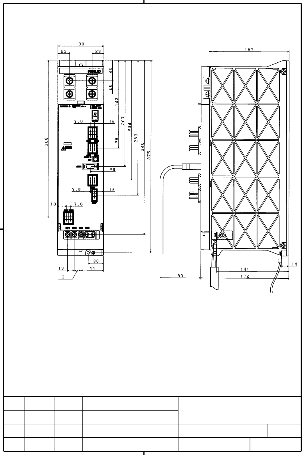
- Page 455.3.1 Power Failure Backup Module (2) A06B-6091-H002 (400V input type) TITLE Power Failure Backup Module Descriptions DRAW. NO. CUST. A-53866E-464 SHEET EDIT. DATE DESIG. DESCRIPTION FANUC LTD 45/93�
- Page 465.3.2 Sub module C (A06B-6077-H010, A06B-6083-H245) Supplement capacitor unit (A06B-6077-H010) DC link terminal block TB1 DC link charge indication LED Terminal hole for flange grounding (M5) 5.3.3 Sub module R See Subsection 4.1.3. TITLE Power Failure Backup Module Descriptions DRAW. NO. CUST. A-53
- Page 475.4 CONNECTOR LAYOUT DIAGRAMS 5.4.1 Power Failure Backup Module (1) A06B-6077-H002 (200V input type) WARNI WARNING Do not touch module components or connected cables while this LED is lit. There is a danger of electric shock. When you touch module components or connected cables, be sure to check the
- Page 485.4.1 Power Failure Backup Module (2) A06B-6091-H002 (400V input type) WARNI WARNING Do not touch module components or connected cables while this LED is lit. There is a danger of electric shock. When you touch module components or connected cables, be sure to check the voltage by a tester, because
- Page 495.5 CONNECTOR OUTSIDE DIMENSIONS (1) Connector for K61 (CX16) Manufacturer: Tyco Electronics AMP Model: 1-178127-6 Pin Number 22.96 16.7 Key (XX) B A (2) For information on the outside dimensions of other connectors and cable wires, refer to the Description B-65282EN or B-65162E. TITLE Power Failure
- Page 505.6 GROUNDING Connect the metal frames of the power failure backup module, sub module C, and sub module R to the ground plate of the cabinet. The conductor diameter of the grounding cables must be the same as that of the PSM. 5.6.1 Power Failure Backup Module (1) A06B-6077-H002 (200V input type) M5
- Page 515.6.1 Power Failure Backup Module (2) A06B-6091-H002 (400V input type) M5 screw System ground Frame ground (ground plate of the cabinet) TITLE Power Failure Backup Module Descriptions DRAW. NO. CUST. A-53866E-464 SHEET EDIT. DATE DESIG. DESCRIPTION FANUC LTD 51/93�
- Page 525.6.2 Sub module C and Supplement capacitor unit M5 screw System ground Frame ground (ground plate of the cabinet) TITLE Power Failure Backup Module Descriptions DRAW. NO. CUST. A-53866E-464 SHEET EDIT. DATE DESIG. DESCRIPTION FANUC LTD 52/93�
- Page 535.6.3 Sub module R M4 screw System ground Frame ground (ground plate of the cabinet) TITLE Power Failure Backup Module Descriptions DRAW. NO. CUST. A-53866E-464 SHEET EDIT. DATE DESIG. DESCRIPTION FANUC LTD 53/93�
- Page 546. FUNCTIONS 6.1 FUNCTION DESCRIPTION The power failure backup module performs the following controls: (1) Power failure detection Detects a power failure and outputs a power failure detection signal. In response to this signal, perform ladder processing that starts actions for machine protection (s
- Page 55(2) Control of the charging of the capacitor inside the sub module Controls the charging of the capacitor inside sub module C. Charging of sub module C starts when the DC link has been charged completely and the PSM enters the ready state (*CRDY=0) after the MCC is turned ON. The charging time depen
- Page 56(4) Resistance regeneration control After a power failure occurs, causes the energy resulting from the deceleration of the motor to be consumed in the resistor inside sub module R. In normal operation, the energy resulting from the deceleration of the motor is regenerated into power, not flowing thr
- Page 57(5) Control of control power supply <1> For the A06B-6077-H002 (200V type) After a power failure occurs, controls the supply of the DC link voltage to the control supply for the PSM and the CNC. Internal circuit Power failure backup module Switching circuit PSM Fuse AC200V CX12 CNC CX13 Other contro
- Page 58Supplement capacitor unit The supplement capacitor unit is used with the power failure backup module A06B-6077-H002 (200V input type) if the motor is to be operated in the DC link voltage range of 200V or less. After a power failure, the DC link voltage is used to maintain the control power supply (
- Page 59The supplement capacitor unit is required for the Retract function at power failure, which may be used to drive motors in the DC link voltage range of 200V or less. The supplement capacitor unit is not required for the stop distance reduction function at power failure because the DC link voltage is
- Page 606.2 CONTROL SEQUENCES 6.2.1 Power-ON Sequence (1) For the A06B-6077-H002 (200V type) AC200V ON Main breaker (200 VAC) Output of 200 VAC from CX13 Approx. 1 sec Power failure detection Power failure detection enabled (Note 1) CX17 internal relay Internal relay contact ON *MCON signal (CNC to SVM) CX3
- Page 616.2.1 Power-ON Sequence (2) For the A06B-6091-H002 (400V type) AC400V ON Main breaker (400 VAC) AC200V ON Control power (CX27 input) Output of 200 VAC from CX28 Approx. 1 sec Power failure detection Power failure detection enabled (Note 1) CX17 internal relay Internal relay contact ON *MCON signal (
- Page 626.2.2 MCC Shutoff Sequence The sequence is common to the A06B-6077-H002 (200V type) and the A06B-6091-H002 (400V type). MCC ON OFF *CRDY (PSM internal ready signal) RDY (CX16 B3) LED indication "0" indication "-" indication When the MCC is shut off, RDY becomes 0. At the same time, the LED indicatio
- Page 636.2.3 Sequence in the Event of a Power Failure (Control of the Supply of the DC Link Voltage to the Control Power Supply) (2) For the A06B-6091-H002 (400V type) Power failure Input voltage (400 VAC/200 VAC) Power failure detected Power failure detection signal *PFL (CX16 B2) DC link voltage Approx.
- Page 646.2.4 Sequence in the Event of a Power Failure (Control of the Supply of Energy from Sub module C) This sequence is common to the A06B-6077-H002 (200V type) and the A06B-6091-H002 (400V type). Power failure Power failure detected Input power Power failure detection *PFL (CX16 B2) CX17 internal relay
- Page 656.2.5 Sequence in the Event of a Power Failure (Resistance Regeneration Control) This sequence is common to the A06B-6077-H002 (200V type) and the A06B-6091-H002 (400V type). Power failure Power failure detected Input voltage Power failure detection *PFL (CX16 B2) CX17 internal relay Internal relay
- Page 666.2.6 Sequence if an Alarm or Error Occurs in the Power Failure Backup Module An alarm occurs in the power failure backup module. Alarm *ALM (CX16 B1) RDY (CX16 B3) LED indication "0" indication Alarm No. indication Machine operation state Normal operation Stop processing Machine stop MCC ON OFF If
- Page 676.3 STATUS INDICATION The state of the power failure backup module is indicated on a 7-segment LED. Indication Name Description - NOT Indicates that the power failure backup module is not yet ready. READY 0 READY Indicates that the charging of sub module C is completed so that power failure backup o
- Page 686.4 ALARMS To protect the machine and itself in the event of an error, the power failure backup module provides the error detection and protection functions given in the table below. If an error occurs in the power failure backup module, you can no longer perform power failure backup operation to pr
- Page 694 Regenerative The regenerative Sub module R has entered the all-time ON state due resistor resistor inside sub to an error in the regenerative circuit. overheat alarm module R has Replace the power failure backup module. overheated. 5 Thyristor drive The voltage of the An error occurred in the thyr
- Page 706.6 CONTROL SIGNALS The table below gives the control signals for the power failure backup module. Control Connector Pin number Description signal *SYNC CX16 A3 This signal input is used to disable the detection of a power failure in the DC link. By making this signal 24 V, the detection of a power
- Page 717. SIGNAL HANDLING AND PARAMETER SETTING The machine protection functions at power failure control the necessary machine protection operations in the CNC, in response to the power failure detection signal output from the power failure backup module as soon as a power failure occurs. This chapter pro
- Page 727.1.1 If Using the Electronic Gear Box Function, Simple Electronic Gear Box Function, and Hobbing Machine Function Retraction is performed with the retract signal (RTRCT). When the power failure detection signal (*PFL) changes from "1" to "0", change the retract signal (RTRCT) from "0" to "1". Power
- Page 737.1.2 If Using the High-Speed Cycle Cutting Function The high-speed cycle cutting retract function option is required. Retraction is performed with the high-speed cycle cutting retract signal (HSRT). When the power failure detection signal (*PFL) changes from "1" to "0", change the high-speed cycle
- Page 747.1.3 Power Failure Retract in a Machining Center and a Lathe The general-purpose retract function option is required. (For the FS0i-C, this is a standard function.) As with the electronic gear box function, perform retraction with the retract signal (RTRCT). When the power failure detection signal
- Page 757.1.4 Notes on Setting the Parameters for the Retract function at power failure The retract amount parameter must be set to a value equal to or greater than twice the travel distance necessary for preventing the workpiece and the tool from interfering with each other. Supplementary explanation Chang
- Page 767.2 STOP DISTANCE REDUCTION FUNCTION AT POWER FAILURE 7.2.1 Deceleration on the Feed Axis to a Stop Set the parameters for the stop distance reduction function (standard function). When the power failure detection signal (*PFL) from "1" to "0", set the emergency stop (*ESP) of the CNC to "0". Power
- Page 77NOTE Set the above parameters for all the axes for which the stop distance reduction function at power failure is to be used. If you use a multiaxis amplifier (2- or 3-axis amplifier) for an axis to which the stop distance reduction function at power failure is to be applied, set the brake control f
- Page 787.2.2 Deceleration of the Spindle to a Stop When the power failure detection signal (*PFL) changes from "1" to "0", change the spindle control input signal *ESPA (*ESPB, *ESPC, or *ESPD) to "0". Power failure detected *PFL *ESPA (*ESPB,*ESPC,*ESPD) *PFL: Power failure detection signal Output from co
- Page 797.3 GRAVITY-AXIS DROP PREVENTION FUNCTION AT POWER FAILURE Set the parameters for the brake control function (standard function). When the power failure detection signal (*PFL) from "1" to "0", apply the brake and set the emergency stop (*ESP) of the CNC to "0" at the same time. Power failure detect
- Page 80NOTE 1. Even if the gravity-axis drop prevention function at power failure operates normally, there will be a drop corresponding to the backlash of the brake (up to 20 µm for a ball screw pitch of 10 mm). If the drop corresponding to the backlash presents a problem, you can cause pull-up along the v
- Page 818. SELECTING SUB MODULES 8.1 SELECTING SUB MODULE R Use the following two conditions to determine the applicable sub module R types and the number of sub modules R to be connected. Condition <1>: Sum of the maximum outputs of the motors to be decelerated simultaneously in the event of a power failur
- Page 82The sum of the maximum outputs of the motors to be decelerated simultaneously in the event of a power failure is 32.2 kW (condition <1>). The sum of the products of the maximum outputs and the deceleration times of the each motor to be decelerated in the event of a power failure is 23.62 kWsec (cond
- Page 838.2 SELECTING SUB MODULE C If you use the Retract function at power failure, you need sub module C as the source of energy for driving motors after a power failure occurs. The amount of energy required for retraction differs depending on the machine configuration; connect as many sub modules C as ne
- Page 848.2.1 Calculating the Amount of Energy That Can Be Supplied Per Sub module C Sub module C is charged to about the same voltage of the DC link voltage at all times through the charge circuit inside the power failure backup module. The amount of energy per sub module C depends on the voltage of the su
- Page 858.2.2 Calculating the Amount of Energy Required for Retraction in the Event of a Power Failure The energy required after a power failure is the sum of (1) and (2) below. (1) Energy required for the cutting from the time a power failure occurs until retraction is started (expression <3>) (2) Energy f
- Page 86(2) Calculating the energy W3 [J] for movement along the retract axis. The energy for movement along the retract axis is the sum of the energy required for acceleration to the retract speed (area(2)-1) and the energy required against friction (area(2)-2). (a) For the SI unit system −3 2 d W 3 = 5.48
- Page 87Selection example: If performing retraction in a gear machine in the event of a power failure. Conditions Sub module C used is the A06B-6077-H010 (for 200V) Maximum cutting output on the synchronous axis P2=10[kW] (spindle: 7[kW], servo axis: 3[kW]) Retract axis Rotor inertia of the motor Jm=0.0062[
- Page 889. RESTRICTIONS ON CONNECTING αi SERIES AMPLIFIERS If connecting the power failure backup module to αi series amplifiers, you must provide external control power supply for some of the amplifiers depending on the number of amplifiers to be connected. 9.1 CONDITIONS UNDER WHICH AN EXTERNAL CONTROL PO
- Page 899.2 CONNECTION TO BE MADE IF PROVIDING AN EXTERNAL CONTROL POWER SUPPLY If the number of SVMs to be connected to the PSM exceeds the number determined as described earlier, provide an external 24V control power supply. (1) Connection The following shows an example in which an external 24V control po
- Page 90(2) Power ON sequence The start of the supply of 24V power from the external power supply to the CNC/SPM and turning ON of the 200 VAC control power supply for the PSM (CX1A) must conform to the timing chart shown below. Usually, you can satisfy the timing requirements if you start the supply of 24-
- Page 9110. OPERATION CHECKS 10.1 RETRACT FUNCTION AT POWER FAILURE This section describes how to check operation if you apply the Retract function at power failure to a gear cutting machine. (1) Sequence check Check that in the idle state, turning off the main breaker of the power magnetics cabinet (for a
- Page 92Completion of retraction Retract axis TSA of workpiece and tool The area corresponds to the amount of travel along the retract axis. The time until the workpiece and tool travel to a position where Start of retraction they do not interfere with each other is assumed t1. Power failure Check method Ti
- Page 9310.2 STOP DISTANCE REDUCTION FUNCTION AT POWER FAILURE (1) Check of the backup operation for the control power supply Check the control power is maintained with a power failure backup module at power failure according to the following method. Turn off the main breaker (for a dummy power failure) whi