FANUC i-Cell Operators manual Page 596
Operators manual
E.DETAILS OF CIMPLICITY POINTS APPENDIX B-75074EN/04
- 570 -
Displaying the overview status
The status character strings such as [Running] and their display colors
on the overview screen are determined as follows.
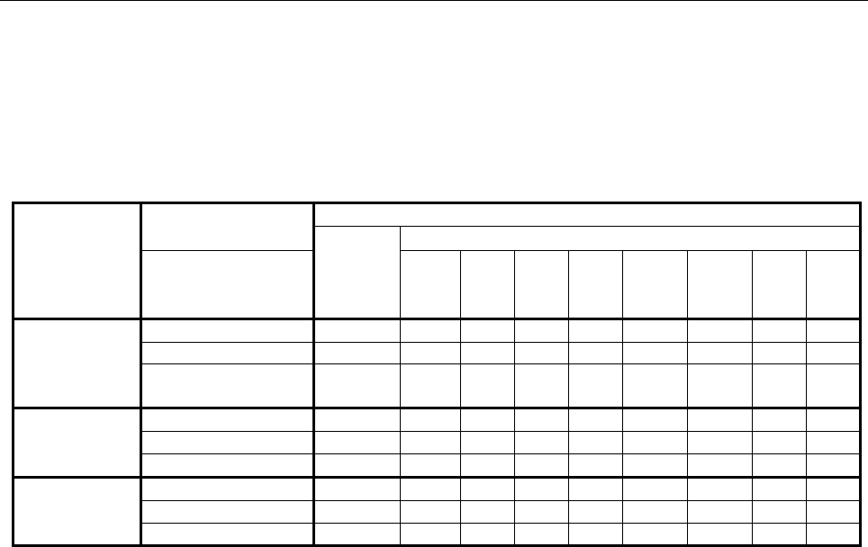
<1> Read the PMC area to obtain the OP, SA, STL, SPL, MA, AL, and
ESP signals of the NC. To do this, create the following points.
Then, read the data.
PMC area
Point
Bit
CNC
Name
Array
element
count
Address
#7 #6 #5 #4 #3 #2 #1 #0
F_F0 8 F0000 OP SA STL SPL
F_F1 8 F0001 MA AL
FS30i/31i/32i
FS16i/18i/21i
Power Mate i
FS0i
F_ESP None G0008 ESP
F_F0 8 F0000 MA SA OP STL SPL AL
F_F1 8 F0001
FS15, FS15i
F_ESP None G0000 ESP
F_F0 8 F0148 OP SA STL SPL
F_F1 8 F0149 MA AL
FS0
F_ESP None G0121 ESP
<2> Create F_OP, F_SA, F_STL, F_SPL, F_MA, and F_AL from the
points listed above. Create F_ESPV from the ESP signal.
<3> Calculate F_STATUS from the combination of F_OP, F_SA,
F_STL, F_SPL, F_MA, F_AL, and F_ESPV. On the basis of the
F_STATUS value, the color animation function of the screen
determines the character string to be displayed and its color on the
overview screen.
In addition to the PMC area signals listed above, F_COM_COND is
also checked.
If the machine is connected by DNC2, the value of F_COM_COND
becomes 0 while the NC program management screen is displayed. In
the meantime, neither PMC area signals nor machining results are
collected.
Contents Summary of FANUC i-Cell Operators manual
- Page 1* FANUC CIMPLICITY CELL OPERATOR’S MANUAL B-75074EN/04
- Page 2• No part of this manual may be reproduced in any form. • All specifications and designs are subject to change without notice. The export of this product is subject to the authorization of the government of the country from where the product is exported. In this manual we have tried as much as possi
- Page 3B-75074EN/04 SAFETY PRECAUTIONS SAFETY PRECAUTIONS SAFETY PRECAUTIONS describes notes, cautions and warnings to be observed for safe handling of those machines that have the FANUC CIMPLICITY i CELL and FANUC CNC installed. Before using the functions described in this manual, be sure to read SAFETY
- Page 4SAFETY PRECAUTIONS B-75074EN/04 1.1 DEFINITION OF WARNING, CAUTION, AND NOTE This manual includes safety precautions for protecting the user and preventing damage to the machine. Precautions are classified into Warning and Caution according to their bearing on safety. Also, supplementary information
- Page 5B-75074EN/04 SAFETY PRECAUTIONS 1.2 GENERAL WARNINGS AND CAUTIONS WARNING 1 Before operating the machine, thoroughly check the entered data. Operating the machine with incorrectly specified data may result in the machine behaving unexpectedly, possibly causing damage to the workpiece and/or machine
- Page 6SAFETY PRECAUTIONS B-75074EN/04 CAUTION 1 Immediately after switching on the power, do not touch any of the keys on the MDI panel until the position display or alarm screen appears on the CNC unit. Some of the keys on the MDI panel are dedicated to maintenance or other special operations. Pressing a
- Page 7B-75074EN/04 SAFETY PRECAUTIONS 1.3 WARNING AND CAUTIONS ON THE FANUC CIMPLICITY i CELL Warnings and cautions on the FANUC CIMPLICITY i CELL are provided below and in the text of this manual. Read this manual carefully before using the FANUC CIMPLICITY i CELL, and observe the warnings, cautions,
- Page 8SAFETY PRECAUTIONS B-75074EN/04 Warning and caution on DNC operation WARNING 1 When performing DNC operation, check the NC program. If an incorrect NC program is used, the machine and tool can perform an unexpected operation, thus damaging the workpiece and machine, and causing human injury. 2 When
- Page 9B-75074EN/04 PREFACE PREFACE This manual describes the FANUC CIMPLICITY i CELL that operates on a personal computer (called PC for short). The FANUC CIMPLICITY i CELL is an application that runs on the CIMPLICITY HMI Plant Edition. Using the Ethernet, DNC2, reader/puncher, or Data Server communic
- Page 10PREFACE B-75074EN/04 Related manuals This manual also covers FANUC NCs, their communication functions, and CIMPLICITY related to the use of this software. However, this manual does not cover all required information. Refer to the following manuals in addition to this manual: (1) CIMPLICITY • CIMPLIC
- Page 11B-75074EN/04 PREFACE Article 2 Copyright FANUC possesses the copyright of this software. Accordingly, the customer shall not copy this software for any purpose except for the purpose stipulated in Article 1 "Licensing of right for use". Article 3 Restrictions The customer shall not transfer, lend, s
- Page 12
- Page 13B-75074EN/04 TABLE OF CONTENTS TABLE OF CONTENTS SAFETY PRECAUTIONS............................................................................s-1 PREFACE ....................................................................................................p-1 I. GENERAL 1 OVERVIEW ...................
- Page 14TABLE OF CONTENTS B-75074EN/04 5.2.4 Planned Parts Count Input......................................................................................54 5.3 TOOL LIFE MANAGEMENT........................................................................ 55 5.3.1 Display Information .......................
- Page 15B-75074EN/04 TABLE OF CONTENTS 2.3.1 Setting Up the TCP/IP (Basic Function) for Windows NT ....................................84 2.3.2 Setting the TCP/IP (Basic Function) for Windows NT..........................................85 2.3.3 Setting the DNS (Mail Function) for Windows NT ................
- Page 16TABLE OF CONTENTS B-75074EN/04 2.1.3 Setting up Machine Information...........................................................................117 2.1.4 Setting up Communication ...................................................................................117 2.1.5 Setting up NC Program Manageme
- Page 17B-75074EN/04 TABLE OF CONTENTS 2.12.1 Machining Result .................................................................................................179 2.12.2 Workpieces Process Result...................................................................................179 2.12.3 Tool Life.........
- Page 18TABLE OF CONTENTS B-75074EN/04 5.4.1 Checking Communication between the Viewer PC and Each NC .......................229 5.4.2 Checking CIMPLICITY Viewer Communication ...............................................231 5.5 EXECUTION....................................................................
- Page 19B-75074EN/04 TABLE OF CONTENTS 5.2.6.2 Communication with a Data Server (FTP server)............................................ 284 5.2.7 Copying, Moving, Deleting, and Renaming Connection Destination Files (Directories)...............................................................................
- Page 20TABLE OF CONTENTS B-75074EN/04 9.4.4 History Signal Setting ..........................................................................................354 9.5 VARIOUS DATA BACKUP/RESTORATION.............................................. 355 9.5.1 Data Backup ..........................................
- Page 21B-75074EN/04 TABLE OF CONTENTS 2.3.1 General-Purpose Tab (Function Switch Tab) Control..........................................396 2.3.2 Back Button..........................................................................................................397 2.3.3 Title Bar..........................
- Page 22TABLE OF CONTENTS B-75074EN/04 3.3.7 WKPCDspMcnCnd - Progress Status Display Table...........................................433 3.3.8 WKPCDspLastState - Machining End State Display Table.................................434 4 REFERENCING THE DATABASE..................................................
- Page 23B-75074EN/04 TABLE OF CONTENTS B.1.3 Configuring a Small-scale Network .....................................................................487 B.1.4 Configuring a Large-scale Network .....................................................................487 B.2 SETTING THE EMBEDDED Ethernet FOR Serie
- Page 24TABLE OF CONTENTS B-75074EN/04 B.5.3 Setting the FTP File Transfer Functions ..............................................................518 B.5.3.1 Parameter setting screen for the FTP file transfer function ............................. 518 B.5.3.2 Configuring a small-scale network .............
- Page 25B-75074EN/04 TABLE OF CONTENTS F.2.2 Internet Information Service for Windows 2000..................................................589 G CONNECTION TO THE INTERNET.................................................... 594 G.1 EXAMPLE CONTRACT FOR DIALUP CONNECTION ............................. 595 H
- Page 26
- Page 27I. GENERA
- Page 28
- Page 29B-75074EN/04 GENERAL 1.OVERVIEW 1 OVERVIEW Organization of this part This part (GENERAL) outlines the i CELL. -3-
- Page 302.ABOUT THE FANUC CIMPLICITY i CELL GENERAL B-75074EN/04 2 ABOUT THE FANUC CIMPLICITY i CELL The FANUC CIMPLICITY i CELL is a software package for centrally manage multiple CNC machine tools connected to a network. The i CELL supports normal operations such as part machining and machining result col
- Page 31B-75074EN/04 GENERAL 2.ABOUT THE FANUC CIMPLICITY i CELL computer (server) that is performing central management with the i CELL. With the Web view function, operating status monitored with the i CELL can be monitored from a remote personal computer via the Internet by using a browser such as Intern
- Page 323.OPERATING ENVIRONMENT GENERAL B-75074EN/04 3 OPERATING ENVIRONMENT This chapter describes the operating environment for using the i CELL. Communication functions, and available CNCs and functions i CELL supports four communication functions, FOCAS2/Ethernet, DNC2, Reader/Puncher, and Data Server.
- Page 33B-75074EN/04 GENERAL 3.OPERATING ENVIRONMENT NOTE *1 Set an FTP server on the PC side, and set the setting information (port number, IP address, user name, password, login directory) in the parameters for the FTP file transfer function of the NC. *2 Function under development *3 The following functi
- Page 343.OPERATING ENVIRONMENT GENERAL B-75074EN/04 In other words, when only the FTP client function of the NC program management screen is used, the connection destination, namely, a Data Server or PC, is not counted in the number of units that require the options above. So, when I/O operation to and fro
- Page 35B-75074EN/04 GENERAL 3.OPERATING ENVIRONMENT 3.1 CNC Usable CNCs - When the FOCAS2/Ethernet is used An Ethernet is required for the following CNCs: - Series 30i-MODEL A, Series 300i-MODEL A, Series 300is-MODEL A - Series 31i-MODEL A, Series 310i-MODEL A, Series 310is-MODEL A - Series 32i-MODEL A, Se
- Page 363.OPERATING ENVIRONMENT GENERAL B-75074EN/04 - When the DNC2 is used An DNC2 is required for the following CNCs: Series 0-MODEL C, Series 15-MODEL A/B Series 16-MODEL A/B/C, Series 18-MODEL A/B/C Series 16i-MODEL A/B, Series 18i-MODEL A/B Series 21i-MODEL A/B NOTE 1 The i CELL can be used with one-p
- Page 37B-75074EN/04 GENERAL 3.OPERATING ENVIRONMENT - When the Data Server is used With the following CNCs, the FAST Data Server or Data Server of 10BASE-T type is used: - Series 30i-MODEL A, Series 300i-MODEL A, Series 300is -MODEL A - Series 31i-MODEL A, Series 310i-MODEL A, Series 310is -MODEL A - Serie
- Page 383.OPERATING ENVIRONMENT GENERAL B-75074EN/04 Ethernet boards or Data Server boards and CNC options The table below indicates the Ethernet boards or Data Server boards usable with the i CELL, and required CNC options. Ethernet boards or Data Server boards and required options Applicable Drawing No. N
- Page 39B-75074EN/04 GENERAL 3.OPERATING ENVIRONMENT Ethernet boards or Data Server boards and required options Applicable Drawing No. Name CNC option Control software model number A02B-XXXX-S707 (*1) FS16i /18i /21i A02B-0281-J561 21 ATA FAST Data A02B-0265-J140 A02B-0207-J800 (*2) -TA/MA #6567 Server for
- Page 403.OPERATING ENVIRONMENT GENERAL B-75074EN/04 This option is required when the FOCAS2/Ethernet function is used. (*2) A02B-0207-J800: Extended driver library for Series 16i/18i/21i This option is required when Model A is used. This option is not required for Model B, regardless of whether the embedde
- Page 41B-75074EN/04 GENERAL 3.OPERATING ENVIRONMENT DNC2 boards and CNC options The table below indicates the DNC2 boards usable with the i CELL, and required CNC options. DNC2 boards and required options Applicable Drawing No Name CNC option Control software model number A02B-XXXX-J878 (*1) DNC2 card for
- Page 423.OPERATING ENVIRONMENT GENERAL B-75074EN/04 (*5) A02B-XXXX-J908 : DNC2 for Series 16/18 A02B-XXXX-J902 : External control of I/O devices for Series 16/18 A02B-XXXX-J956 : Background edit for Series 16/18 Specify one of the following drawing numbers in XXXX according to the NC type: 0222 (16 -TC) 02
- Page 43B-75074EN/04 GENERAL 3.OPERATING ENVIRONMENT CNC options for functions other than the Ethernet, Data Server, and DNC2 functions The table indicates an option required for each function used. However, the options below are standard with the Series 0i-MODEL B/C. The i CELL function which can be used b
- Page 443.OPERATING ENVIRONMENT GENERAL B-75074EN/04 3.2 PERSONAL COMPUTER/HARDWARE The hardware used to operate the i CELL is described below. Computer Select <1> or <2> below. Also select the item(s) required for the communication protocol to be used from <3>. <1> Computer compatible with IBM PC/AT • CPU:
- Page 45B-75074EN/04 GENERAL 3.OPERATING ENVIRONMENT <3> Communication hardware • Ethernet board (if the FOCAS2/Ethernet or Data Server protocol is used) • RS-232C port (if the DNC2 protocol is used) • RS-232C expansion board (if the DNC2 or Reader/Puncher protocol is used) The RS-232C expansion board to be
- Page 463.OPERATING ENVIRONMENT GENERAL B-75074EN/04 RS-232C connection cable The following interface specifications apply between the PC and NC. If the RS-232C expansion board is RS-232C main unit port AccelePort 4p/8p DTE, DB25 male. PC side NC side PC side NC side DSUB 25pin DSUB 25pin DSUB 9pin DSUB 25p
- Page 47B-75074EN/04 GENERAL 3.OPERATING ENVIRONMENT 3.3 PERSONAL COMPUTER/SOFTWARE Operating system and related software Using Windows NT (A) When the Web function is used All of <1> to <3> below are required. <1> Microsoft Windows NT Server 4.0 ServicePack 6a and later <2> Microsoft Internet Information
- Page 483.OPERATING ENVIRONMENT GENERAL B-75074EN/04 NOTE To use the i CELL with Windows 2000, the user needs to belong to the Power Users group. To make various settings on the setting screen, the user needs to belong to the Administrators group. Using Windows XP (A) When the Web function is used All of <1
- Page 49B-75074EN/04 GENERAL 3.OPERATING ENVIRONMENT CIMPLICITY system i CELL can operate on the following CIMPLICITY versions: CIMPLICITY HMI Plant Edition Version 6.1 (English or Japanese version) Running both the Japanese and English versions of CIMPLICITY requires CIMPLICITY HMI Plant Edition Version 6.
- Page 503.OPERATING ENVIRONMENT GENERAL B-75074EN/04 3.4 NETWORK CONFIGURATION Basic configuration When i CELL is used with the Ethernet, the method of setting on the setting screen varies, depending on the network configuration. Check the network configuration. Specifically, check if the i CELL server PC a
- Page 51B-75074EN/04 GENERAL 3.OPERATING ENVIRONMENT It is therefore necessary to set up the IP routing function in the router shown in Fig.3.4(d) in such a way that network A, to which the NCs belong, can communicate with network B, to which the viewer PC belongs, using TCP/IP. Set up the router in such a
- Page 523.OPERATING ENVIRONMENT GENERAL B-75074EN/04 3.5 CONTRACT WITH INTERNET SERVICE PROVIDERS When the user does not use the mail and Web functions, no contract with an Internet service provider is required. For connection with a provider, use the ISDN line. (A) When the mail function only is used with
- Page 53B-75074EN/04 GENERAL 4.NC PROGRAM MANAGEMENT 4 NC PROGRAM MANAGEMENT - 27 -
- Page 544.NC PROGRAM MANAGEMENT GENERAL B-75074EN/04 4.1 OVERVIEW NC program management connects a personal computer as a NC program file server to multiple NCs. NC program management also allows connection with a Data Server or PC. For communication with a Data Server or PC, the operating side needs to be
- Page 55B-75074EN/04 GENERAL 4.NC PROGRAM MANAGEMENT Communication protocol Function FOCAS2/ Reader/ Data DNC2 Ethernet puncher Server Management of NC program files in the NC memory by operating the personal computer A list of NC programs held in the NC memory can be displayed on O O - O the NC program man
- Page 564.NC PROGRAM MANAGEMENT GENERAL B-75074EN/04 4.2 NC PROGRAM TRANSFER This section describes NC program transfer by operating the NC program management screen and NC. 4.2.1 NC Program Transfer by Operating the NC Program Management Screen NC programs can be transferred by operating the NC program man
- Page 57B-75074EN/04 GENERAL 4.NC PROGRAM MANAGEMENT The NC program management screen displays this default directory or an arbitrary directory, and a list of NC programs in the NC memory or Data Server (FTP server). The operator transfers NC programs by operating this screen. List of files in the default d
- Page 584.NC PROGRAM MANAGEMENT GENERAL B-75074EN/04 4.2.2 NC Program Transfer by Operating the NC To transfer an NC program by operating the NC, you cannot specify the directory path to a file on the personal computer on the NC. On the NC, specify an NC program with the file name, file number, or NC progra
- Page 59B-75074EN/04 GENERAL 4.NC PROGRAM MANAGEMENT The following table lists the methods for determining an NC program to be downloaded by operating. Methods for determining an NC program to be downloaded by operating the NC Used key Method for determining an NC program to be transferred File name Searche
- Page 604.NC PROGRAM MANAGEMENT GENERAL B-75074EN/04 4.3 NC PROGRAM FORMAT NC programs used with the system are managed under the formats indicated below. The program field must contain a main program including an NC program number, or must contain a subprogram. Example 1: Main program ending with M30 % ; O
- Page 61B-75074EN/04 GENERAL 4.NC PROGRAM MANAGEMENT Use ASCII as the character code for NC programs. Some editors may be set to create a file using Unicode. An error occurs if an attempt is made to transfer an NC program created using Unicode. Whether an NC program is created using Unicode can be checked a
- Page 624.NC PROGRAM MANAGEMENT GENERAL B-75074EN/04 4.4 SUBPROGRAM TRANSFER FUNCTION Subprogram transfer function When an NC program is downloaded, and a subprogram call is included in the NC program, the subprogram transfer function downloads the subprogram as well. With a CNC supporting file name managem
- Page 63B-75074EN/04 GENERAL 4.NC PROGRAM MANAGEMENT Subprogram file name A subprogram file name must be described in the format "O" + 4- or 8-digit-number + "." + 3-character-extension. For example, a subprogram file name may be O0001.DAT. A 3-character extension must be registered in [Subprogram extension
- Page 644.NC PROGRAM MANAGEMENT GENERAL B-75074EN/04 4.4.1 Details of the Subprogram Batch Transfer Function Subprogram call format A main program can use four subprogram call formats: (1) M98PxxxxLyy (2) M98Pyyxxxx (3) G65PxxxxLyy (4) G66PxxxxLyy (5) M98P
Lyy (6) G65P Lyy (7) G66P - Page 65B-75074EN/04 GENERAL 4.NC PROGRAM MANAGEMENT 4.4.2 Details of the Subprogram Expanded Transfer Function Subprogram call format A main program can use four subprogram call formats: (1) M98PxxxxLyy (2) M98Pyyxxxx (3) G65PxxxxLyy (4) G66PxxxxLyy (5) M98P
Lyy (6) G65P Lyy (7) G66P - Page 664.NC PROGRAM MANAGEMENT GENERAL B-75074EN/04 4.5 LIST FILE TRANSFER FUNCTION List file transfer function The list file transfer function transfers multiple NC programs described in "List file" to the NC. With a CNC supporting file name management, file names can be written in a list file. A list fil
- Page 67B-75074EN/04 GENERAL 4.NC PROGRAM MANAGEMENT List file name A 3-character extension for a list file must be registered in [List file extension] of the [General] panel on the NC Program Management screen. A list file can be created and edited only on the LISTFILE EDITOR screen. When a list file is sa
- Page 684.NC PROGRAM MANAGEMENT GENERAL B-75074EN/04 4.5.2 Details of List File Expended Transfer Function The multiple main NC programs registered in a list file are transferred after being linked into a single NC program. The O numbers, file names, and M30 and M02 codes in the registered NC programs are n
- Page 69B-75074EN/04 GENERAL 4.NC PROGRAM MANAGEMENT NOTE 1 When using this function, check [Wait for send buffer to become 0 before proceeding to next record in expanded transfer] of the [Download] panel on the machine setting screen. 2 Actual data transfer is affected by the send buffer on the personal co
- Page 705.OPERATION MONITOR GENERAL B-75074EN/04 5 OPERATION MONITOR The operation monitor function monitors the operating status of the machine and collects machining results. The operation monitor function has the screens described below. Operation result screen A power-on time, operating time, cutting ti
- Page 71B-75074EN/04 GENERAL 5.OPERATION MONITOR 5.1 OPERATION RESULT SCREEN Data created by the operating time and parts count display option of the NC is read periodically and is summarized monthly for display. 5.1.1 Creating Operation Results The following data created by the operating time and parts cou
- Page 725.OPERATION MONITOR GENERAL B-75074EN/04 5.1.2 Display Information Monthly report on power-on time, operating time, and cutting time (bar charts) For a specified NC, power-on time, operating time, and cutting time data is displayed as bar charts. Monthly report on machined parts count (bar chart) Fo
- Page 73B-75074EN/04 GENERAL 5.OPERATION MONITOR Monthly report on power-on time, operating time, operating time, cutting time, and parts count (table) For a specified NC, power-on time, operating time, operating time, cutting time, and parts count data is displayed as a table. - 47 -
- Page 745.OPERATION MONITOR GENERAL B-75074EN/04 5.2 WORKPIECE MACHINING RESULTS Based on data (machine ID, workpiece ID, O number, start time, end time, machining end ID, user area ID, and sequence number) collected at the start and end of machining, workpiece machining results are displayed. Information d
- Page 75B-75074EN/04 GENERAL 5.OPERATION MONITOR 5.2.2 Display Information Current progress status display When each machine has a workpiece currently being machined (when the start time is latest, and end time, machining end ID, and user area ID data to be obtained at machining end time is not obtained yet
- Page 765.OPERATION MONITOR GENERAL B-75074EN/04 Log display Log information such as the machining times and end states of machined workpieces is displayed sequentially in the order from the latest to oldest log start time. The user can choose from four types of display: no specification, machine specificat
- Page 77B-75074EN/04 GENERAL 5.OPERATION MONITOR Example of display (no specification) Machining end state display The summarized results based on the display number of a machining end ID set on the setting screen are displayed. Two formats of display are available: table format and pie chart format. • Tabl
- Page 785.OPERATION MONITOR GENERAL B-75074EN/04 Example of display (with workpiece specification) • Pie chart format In pie chart format, data is displayed for a workpiece. So, the user can choose from two types of display: workpiece specification and machine/workpiece specification. For each of these opti
- Page 79B-75074EN/04 GENERAL 5.OPERATION MONITOR 5.2.3 Display Format Alteration For the particular items (machine, workpiece, O number, user area, and date and time) of the machine specification list box, workpiece specification list box, progress status display, log display, and machining end state displa
- Page 805.OPERATION MONITOR GENERAL B-75074EN/04 5.2.4 Planned Parts Count Input A planned parts count used for current progress status display and machining end state display (table or pie chart) can be altered from the screen. Example of machine/workpiece extraction screen Select machines, workpieces, and
- Page 81B-75074EN/04 GENERAL 5.OPERATION MONITOR 5.3 TOOL LIFE MANAGEMENT This screen has the same effect as the tool life screen of the NC. Two types of display are available: tool group list display and tool group detail display. NOTE 1 The NC must have the tool life management option selected. With Serie
- Page 825.OPERATION MONITOR GENERAL B-75074EN/04 Tool group detail display The details of a tool group number selected on the tool group list display screen are displayed. Example of display - 56 -
- Page 83B-75074EN/04 GENERAL 6.NC DISPLAY AND OPERATION 6 NC DISPLAY AND OPERATION With the NC display and operation function, NC state can be displayed and parameters can be set for each NC. This function can display the following NC states: 1. CNC status 2. O number and program number 3. Current position
- Page 846.NC DISPLAY AND OPERATION GENERAL B-75074EN/04 Parameter setting screen Diagnosis data screen - 58 -
- Page 85B-75074EN/04 GENERAL 7.NC MAINTENANCE 7 NC MAINTENANCE In NC maintenance, operations such as input/output of NC maintenance information and various types of data can be performed for each NC. For NC maintenance, the following functions are available: 1. Alarm history display and external operator me
- Page 867.NC MAINTENANCE GENERAL B-75074EN/04 Various data backup/restoration screen The various data backup/restoration screen enables the following data to be backed up and restored: (1) NC parameters (2) Tool offset data (3) Pitch error compensation data (4) Custom macro variables (numbers in the five hu
- Page 87B-75074EN/04 GENERAL 7.NC MAINTENANCE In automatic backup, the following NC data can be automatically backed up to the personal computer: • Alarm history data • Operation history data • Message history data • NC parameters • Tool offset data • Pitch error compensation data • Custom macro variables (
- Page 887.NC MAINTENANCE GENERAL B-75074EN/04 Screen for displaying various backup data items On the backup data display screen, automatically backed up alarm history data, message history data, and operation history data can be displayed. A display period can be specified. NOTE To use message history data,
- Page 89B-75074EN/04 GENERAL 8.MAIL FUNCTION 8 MAIL FUNCTION The i CELL runs on CIMPLICITY, and CIMPLICITY manages the data of the connected CNC as a point. When a point satisfies a condition, the mail function sends a message to an i-mode cellular phone or remote personal computer. A point that determines
- Page 908.MAIL FUNCTION GENERAL B-75074EN/04 8.1 IMPLEMENTATION OF THE MAIL FUNCTION BY DIAL-UP CONNECTION The i CELL mail function uses a dial-up connection for Internet connection. The jobs described below are required to make a dial-up connection. The i CELL function can be used with 24-hour connection.
- Page 91B-75074EN/04 GENERAL 8.MAIL FUNCTION For connection with a provider, use the ISDN line. Some related terms are described below briefly. Dial-up connection Dialing as required to make a line connection to the access point of an Internet service provider. This mode of connection is the most popular mo
- Page 929.WEB FUNCTION GENERAL B-75074EN/04 9 WEB FUNCTION With the Web function, CNC data collected by the i CELL can be checked from an i-mode cellular phone or remote personal computer. A point to be displayed can be specified for each machine. The value of a point can be converted to a character string
- Page 93B-75074EN/04 GENERAL 9.WEB FUNCTION 9.1 IMPLEMENTING THE MAIL FUNCTION AND WEB FUNCTION WITH 24-HOUR CONNECTION In order to use the i CELL Web function, a 24-hour connection is needed. For a 24-hour connection, the jobs described below are required. • A contract with a provider for a 24-hour connect
- Page 949.WEB FUNCTION GENERAL B-75074EN/04 A related term is described below briefly. 24-hour connection (leased line connection) Line that is connected at all times to the destination, unlike a general switched line. No dialing is required for connection. For 24-hour connection, multiple fixed global IP a
- Page 95II. INSTALLATIO
- Page 96
- Page 97B-75074EN/04 INSTALLATION 1.OVERVIEW 1 OVERVIEW Configuration of Part II Part II, "Installation" consists of the following chapters: 1. OVERVIEW This is the chapter you are reading now. 2. PREPARATION This chapter describes what you should do before installing i CELL and a remote system. 3. INSTALLA
- Page 982.PREPARATION INSTALLATION B-75074EN/04 2 PREPARATION This chapter describes the items you need to set up before installing i CELL in a PC. The items you need to prepare differ depending on the functions to be used with i CELL and the used OS. Look at the following table. For each function, make the
- Page 99B-75074EN/04 INSTALLATION 2.PREPARATION Function to be used Used OS Basic Mail Web Section that describes each item to be set up function function function 2.3.1 Setting Up the TCP/IP (Basic Function) for Windows NT 2.3.2 Setting the TCP/IP (Basic Function) for Windows NT 2.3.3 Setting the DNS (Mail
- Page 1002.PREPARATION INSTALLATION B-75074EN/04 2.1 PREPARATION (FOR Windows XP) This section describes the items you need to prepare when using Windows XP as the OS. When the Web function is used, the Windows 2003 Server, which is the server OS of Windows XP, is needed. 2.1.1 Setting Up the TCP/IP (Basic F
- Page 101B-75074EN/04 INSTALLATION 2.PREPARATION 2.1.2 Setting the TCP/IP (Basic Function) for Windows XP NOTE The user who makes the setting described in this section must have the "administrator privilege". To communicate with NCs using Ethernet, set the TCP/IP. 1. Select [Start] → [Settings] → [Control Pa
- Page 1022.PREPARATION INSTALLATION B-75074EN/04 2.1.3 Setting the DNS (Mail Function) for Windows XP NOTE The user who makes the setting described in this section must have the "administrator privilege". To use a dialup router with the i CELL mail function, you need to set up the domain name system (DNS) of
- Page 103B-75074EN/04 INSTALLATION 2.PREPARATION 2.1.5 Registering the New User "IUSR_ICELL" (Web Function) for Windows 2003 Server To use the Web function, you need to register the new user "IUSR_ICELL". If you do not use the Web function, you do not need to make this setting. NOTE The user who makes the se
- Page 1042.PREPARATION INSTALLATION B-75074EN/04 2.1.7 Installing CIMPLICITY (Basic Function) for Windows XP Before installing i CELL, install CIMPLICITY. See Appendix A, "HOW TO INSTALL AND REGISTER CIMPLICITY," for how to install CIMPLICITY. NOTE 1 The user who installs CIMPLICITY must have the "administra
- Page 105B-75074EN/04 INSTALLATION 2.PREPARATION 2.2 PREPARATION (FOR Windows 2000) This section describes the items you need to prepare when using Windows 2000 as the OS. When the Web function is used, the Windows 2003 Server, which is the server OS of Windows XP, is needed. 2.2.1 Setting Up the TCP/IP (Bas
- Page 1062.PREPARATION INSTALLATION B-75074EN/04 2.2.2 Setting the TCP/IP (Basic Function) for Windows 2000 NOTE The user who makes the setting described in this section must have the "administrator privilege". To communicate with NCs using Ethernet, set the TCP/IP. 1. Select [Start] → [Settings] → [Control
- Page 107B-75074EN/04 INSTALLATION 2.PREPARATION 2.2.3 Setting the DNS (Mail Function) for Windows 2000 NOTE The user who makes the setting described in this section must have the "administrator privilege". To use a dialup router with the i CELL mail function, you need to set up the domain name system (DNS)
- Page 1082.PREPARATION INSTALLATION B-75074EN/04 2.2.5 Registering the New User "IUSR_ICELL" (Web Function) for Windows 2000 To use the Web function, you need to register the new user "IUSR_ICELL". If you do not use the Web function, you do not need to make this setting. NOTE The user who makes the setting d
- Page 109B-75074EN/04 INSTALLATION 2.PREPARATION 2.2.7 Installing CIMPLICITY (Basic Function) for Windows 2000 Before installing i CELL, install CIMPLICITY. See Appendix A, "HOW TO INSTALL AND REGISTER CIMPLICITY," for how to install CIMPLICITY. NOTE 1 The user who installs CIMPLICITY must have the "administ
- Page 1102.PREPARATION INSTALLATION B-75074EN/04 2.3 PREPARATION (FOR Windows NT) This section describes the items you need to prepare when using Windows NT as the OS. 2.3.1 Setting Up the TCP/IP (Basic Function) for Windows NT NOTE The user who makes the setting described in this section must have the "admi
- Page 111B-75074EN/04 INSTALLATION 2.PREPARATION 2.3.2 Setting the TCP/IP (Basic Function) for Windows NT NOTE The user who makes the setting described in this section must have the "administrator privilege". To communicate with NCs using Ethernet, set the TCP/IP. 1. Select [Start] → [Settings] → [Control Pa
- Page 1122.PREPARATION INSTALLATION B-75074EN/04 2.3.3 Setting the DNS (Mail Function) for Windows NT NOTE The user who makes the setting described in this section must have the "administrator privilege". To use a dialup router with the i CELL mail function, you need to set up the domain name system (DNS) of
- Page 113B-75074EN/04 INSTALLATION 2.PREPARATION 2.3.4 Setting Up ODBC (Basic Function) for Windows NT To install a CIMPLICITY viewer run-time environment, set up ODBC. You do not need to set up ODBC when installing a server run-time or development environment, or viewer development environment. (When ODBC s
- Page 1142.PREPARATION INSTALLATION B-75074EN/04 2.3.5 Installing IIS 4.0 (Web Function) for Windows NT NOTE Start The user who makes the setting described in this section must have the "administrator privilege". <1> Installing Internet Information Server 4.0 (IIS4.0) requires the Check the version following
- Page 115B-75074EN/04 INSTALLATION 2.PREPARATION 2.3.6 Registering the New User "IUSR_ICELL" (Web Function) for Windows NT To use the Web function, you need to register the new user "IUSR_ICELL". If you do not use the Web function, you do not need to make this setting. NOTE The user who makes the setting des
- Page 1162.PREPARATION INSTALLATION B-75074EN/04 2.3.8 Installing the CIMPLICITY (Basic Function) for Windows NT Before installing i CELL, install CIMPLICITY. See Appendix A, "HOW TO INSTALL AND REGISTER CIMPLICITY," for explanations about how to install CIMPLICITY. NOTE 1 The user who makes the setting desc
- Page 117B-75074EN/04 INSTALLATION 3.INSTALLATION 3 INSTALLATION The following sections explain how to install i CELL. - 91 -
- Page 1183.INSTALLATION INSTALLATION B-75074EN/04 3.1 INSTALLATION i CELL is installed by executing a setup program from CD-ROM. NOTE 1 The user who install i CELL must have the "administrator privilege". 2 Before starting the installation procedure, stop all application programs. 3 The message "UDP Number f
- Page 119B-75074EN/04 INSTALLATION 3.INSTALLATION 2. The software license agreement terms appear. Read them carefully, and if you agree, click the [Yes] button. 3. On the installation component select screen, the buttons indicating the server and viewer components of the CIMPLICITY viewer are displayed. When
- Page 1203.INSTALLATION INSTALLATION B-75074EN/04 4. Select a folder for installation. Check [Destination Folder], and if it is ok, click the [Next] button. To install i CELL in a different folder, click [Browse] and select the desined folder, then click the [Next] button. Configuration of the directories wh
- Page 121B-75074EN/04 INSTALLATION 3.INSTALLATION Using the directory configuration shown above enables you to use three backup levels, each of which is selected according to what was done. <1> Backup is performed after i CELL is installed and confirmed for normal operation. <2> Backup is performed after a n
- Page 1223.INSTALLATION INSTALLATION B-75074EN/04 6. Before file copy is started, a dialog box appears which prompts you to check what you specified so far. If it is ok, click the [Next] button. Installation begins. 7. The message "UDP Number for C4 Service" shown below appears during installation. You need
- Page 123B-75074EN/04 INSTALLATION 3.INSTALLATION 9. Once the setup is completed, the following message appears. Turn the PC power off and on again. - 97 -
- Page 1243.INSTALLATION INSTALLATION B-75074EN/04 3.2 INFORMATION TO BE AUTOMATICALLY SAVED TO THE TCP/IP SERVICE FILE When i CELL is installed, i CELL entries are automatically registered with the TCP/IP service file so that Windows TCP/IP protocol can be used. The following table lists the services that ar
- Page 125B-75074EN/04 INSTALLATION 3.INSTALLATION UDP number for C4 service As described in *1 under the table above, the same value as the FANUC_C4_SERVER service UDP port number automatically registered in the services file must be set in the corresponding parameter for all NCs. The automatically set port
- Page 1264.UNINSTALLATION INSTALLATION B-75074EN/04 4 UNINSTALLATION - 100 -
- Page 127B-75074EN/04 INSTALLATION 4.UNINSTALLATION 4.1 UNINSTALLATION i CELL can be uninstalled using [Add/Remove Programs] on [Control Panel]. NOTE 1 The user who uninstalls i CELL must have the administrator privilege. 2 Before starting the uninstallation procedure, stop all application programs. 3 When i
- Page 1285.BACKUP AND RESTORATION INSTALLATION B-75074EN/04 5 BACKUP AND RESTORATION - 102 -
- Page 129B-75074EN/04 INSTALLATION 5.BACKUP AND RESTORATION 5.1 BACKUP If you changed the settings of i CELL or customized any i CELL dialog box, be sure to back up i CELL, using the following procedure. When i CELL is backed up, its multiple files and directories are assembled and compacted into a single ba
- Page 1305.BACKUP AND RESTORATION INSTALLATION B-75074EN/04 5.1.2 Selecting Information to be Backed Up This subsection assumes that the NC data is stored using the directory configuration explained in step 5 (determining folders for installation) in Section 3.1, "INSTALLATION". <1> ...\iCELL (You select thi
- Page 131B-75074EN/04 INSTALLATION 5.BACKUP AND RESTORATION 5.1.3 Confirming Backup Archive File Paths A default backup archive file path is set up according to an option selected in the "Select Backup/Restore Directory" frame. The default path names used are as follows: All of i CELL : %iCELL%\..\iCellAll.
- Page 1325.BACKUP AND RESTORATION INSTALLATION B-75074EN/04 5.1.4 Starting Backup Clicking the
button starts backup. If a backup file having the same name as specified now already exists, a prompt message appears to ask whether you want to delete the existing backup file and create a new one under t - Page 133B-75074EN/04 INSTALLATION 5.BACKUP AND RESTORATION 5.1.6 Saving the Backup Archive File Save the backup archive file to an MO, CD-R, or floppy disk. One floppy disk cannot hold the backup archive file unless it is divided, because it is too large to fit on one floppy disk. The iCellBkupRstr dialog b
- Page 1345.BACKUP AND RESTORATION INSTALLATION B-75074EN/04 5.2 RESTORATION To restore data from the backup file, follow the procedure described below. 5.2.1 Installing i CELL If the PC is repaired, and Windows is re-installed in it, i CELL must also be re-installed. If you have not re-installed i CELL, star
- Page 135B-75074EN/04 INSTALLATION 5.BACKUP AND RESTORATION 5.2.4 Starting Restoration Clicking the
button starts restoration. During restriction, the following window appears to display the name of the files to be restored. When restoration is completed, a window appears which lists the restored f - Page 136
- Page 137III. SETTIN
- Page 138
- Page 139B-75074EN/04 SETTING 1.OVERVIEW 1 OVERVIEW Configuration of this part Part III, “Setting,” explains how to set up i CELL. 1. Overview This chapter 2. Basic Setup This chapter describes the basic setup of i CELL. Be sure to read it. 3. Mail This chapter explains how to set up the mail function. 4. We
- Page 1402.BASIC FUNCTIONS SETTING B-75074EN/04 2 BASIC FUNCTIONS This chapter explains how to set up the basic functions of i CELL. To run i CELL, you need to specify what machines (NC) to connect, how to communicate with the machines, and which i CELL function to be enabled for each machine. Some items mus
- Page 141B-75074EN/04 SETTING 2.BASIC FUNCTIONS 2.1 OVERVIEW i CELL supports four communication functions, FOCAS2/Ethernet, DNC2, Reader/Puncher, and Data Server. The following table lists the functions that are available from each communication function and NC type. For each function, see Chapter 3, "OPERAT
- Page 1422.BASIC FUNCTIONS SETTING B-75074EN/04 If you register an order password for the i CELL main package and that for the 10-CNC connection function, for example, you can connect up to 15 machines, up to ten of which are connected using DNC2 or Reader/Puncher. Register the order password Register the or
- Page 143B-75074EN/04 SETTING 2.BASIC FUNCTIONS 2.1.2 Setting up the Number of Machines to be Connected and the Functions to be Used Order password-based machine count management is performed in units of five. The Machine Connect Configuration dialog box determines the number of machines to be actually conne
- Page 1442.BASIC FUNCTIONS SETTING B-75074EN/04 2.1.6 Setting up i CELL i CELL is provided with the overview, machining result, workpiece process result, and tool life functions. Setting up i CELL lets you specify which function to be used for individual machines. The functions you can select differ dependin
- Page 145B-75074EN/04 SETTING 2.BASIC FUNCTIONS 2.2 DIALOG BOX CONFIGURATION 2.2.1 Opening the Configuration Dialog Box To open the Configuration dialog box of i CELL, from the Windows Start menu, select Start, Program, CIMPLICITY i CELL, and Configuration. 2.2.2 Overview Shown below is the Configuration dia
- Page 1462.BASIC FUNCTIONS SETTING B-75074EN/04 2.2.3 Menus The following summarizes the functions of each menu. File Menu Exit Closes the Configuration dialog box. Reflects point settings to CIMPLICITY module as required. Update Point Reflects point settings to CIMPLICITY module. This Configuration command
- Page 147B-75074EN/04 SETTING 2.BASIC FUNCTIONS 2.2.4 How to Change Settings Adding and editing settings Selecting an item from the tree in the left section (<1> in the following figure) displays, in the grid in the right section, a summary of data about the selected item. Double-clicking a row in the grid (
- Page 1482.BASIC FUNCTIONS SETTING B-75074EN/04 2.2.5 Work Flows for Adding and Deleting Machines Adding machines Machines are added in the following work flow. <1> Select Project from the menu bar, then Machine Count Configuration from the Project menu to display the Machine Count Configuration dialog box.
- Page 149B-75074EN/04 SETTING 2.BASIC FUNCTIONS Deleting machines To the contrary to addition, when deleting machines, delete their settings by going up the tree from i CELL to Machine Information. <1> A machine cannot be deleted if the mail or Web function uses data for the machine. To delete the machine, s
- Page 1502.BASIC FUNCTIONS SETTING B-75074EN/04 2.2.6 Setting Change and CIMPLICITY Project i CELL is software that runs on CIMPLICITY module. When a CIMPLICITY i CELL project is operating, restrictions are imposed on the changing of the values of some items. Restrictions on the i CELL project Setting item •
- Page 151B-75074EN/04 SETTING 2.BASIC FUNCTIONS 2.2.7 Stopping and Updating the i CELL Project Stopping To stop the i CELL project, follow this procedure. <1> From the Windows Start menu, select Start, and Program, CIMPLICITY i CELL, then i CELL Project. The CIMPLICITY workbench appears. <2> On the CIMPLICIT
- Page 1522.BASIC FUNCTIONS SETTING B-75074EN/04 2.2.8 Displaying a Dialog Box When the Project Has Not Been Updated If the settings on the i CELL setting screen were changed, but the CIMPLICITY project was not updated, the following dialog box appears when the project is started. Starting the project from th
- Page 153B-75074EN/04 SETTING 2.BASIC FUNCTIONS 2.2.9 If an Attempt to Reflect Point Settings to CIMPLICITY Fails Before closing the Configuration dialog box, reflect point settings to CIMPLICITY if necessary. If this processing fails, the following dialog box appears. Clicking the OK button closes the Confi
- Page 1542.BASIC FUNCTIONS SETTING B-75074EN/04 2.3 MACHINE COUNT CONFIGURATION Selecting Project from the menu bar of the Configuration dialog box, then Machine Count Configuration from the Project menu displays the Machine Count Configuration dialog box. This dialog box lets you register an order password.
- Page 155B-75074EN/04 SETTING 2.BASIC FUNCTIONS 2.4 PROJECT PROPERTY Selecting Project from the menu bar of the Configuration dialog box, then Property from the Project menu displays the Project Property dialog box. This dialog box lets you make the settings related to the entire i CELL project. Connect Spec
- Page 1562.BASIC FUNCTIONS SETTING B-75074EN/04 2.5 MACHINE INFORMATION Selecting “Machine Information” from the tree lists, in the grid, the machines that were previously set up. If you double-click the row of a machine in the grid, or if you click the row of a machine row in the grid and select Edit from t
- Page 157B-75074EN/04 SETTING 2.BASIC FUNCTIONS Paths details Set M (machining type) or T (lathe type) for each CNC setting path. This box is usable only with Series 30i/31i/32i. PMC Spec. Select the PMC specification of the machine. Available only when NC Type is “FS15B”. Clicking the OK button saves what y
- Page 1582.BASIC FUNCTIONS SETTING B-75074EN/04 Automatic machine information update function based on communication (FOCAS2/Ethernet) When communication is performed with the CNC by using FOCAS2/Ethernet, a machine setting can be automatically made by obtaining various types of data from the CNC without set
- Page 159B-75074EN/04 SETTING 2.BASIC FUNCTIONS 2.6 COMMUNICATION 2.6.1 Setting up Communication Selecting “Communication” from the tree lists, in the grid, the communication settings for the machines that have been set up. If you double-click the row of a machine in the grid, or if you click the row of a ma
- Page 1602.BASIC FUNCTIONS SETTING B-75074EN/04 2.6.2 Setting up FOCAS2/Ethernet Communication Selecting “FOCAS2/Ethernet” in the Communication protocol box displays the following: The setting items of this dialog box are explained below: IP Address This box lets you enter the IP address for the NC. There is
- Page 161B-75074EN/04 SETTING 2.BASIC FUNCTIONS Network A The server PC and NCs belong to different Server NC NC Server networks, with a router PC PC connecting the PC and Router NCs. Network B The server PC and NCs belong to the same network. NC NC Fig. 2.6.2(a) Network configuration (1) → C4 server enabled
- Page 1622.BASIC FUNCTIONS SETTING B-75074EN/04 Enable This check box lets you specify whether to enable communication with the NC. To communicate with the NC, turn on the check box. There is no default value. Confirm the Checks that communication between the NC and PC is Communication enabled. Configuration
- Page 163B-75074EN/04 SETTING 2.BASIC FUNCTIONS Once you set up the i CELL function, the Communication dialog box appears as shown below. If the title of the dialog box contains the phrase “(Point is defined),” you cannot change the communication protocol. To change the communication protocol, clear all the
- Page 1642.BASIC FUNCTIONS SETTING B-75074EN/04 2.6.3 Confirming the FOCAS2/Ethernet Communication Setting Clicking the
button on the FOCAS2/Ethernet communication setting screen displays a screen for confirming the FOCAS2/Ethernet communication setting. NOTE The but - Page 165B-75074EN/04 SETTING 2.BASIC FUNCTIONS PH Power Mate i -H 0 Series 0i M/T: Indicates an M/T type. M Machining center T Lathe MM M series two-path control TT T series two-/three-path control MT T series with the complex machining function P Punch/press (Caution: This model cannot be connected to i CE
- Page 1662.BASIC FUNCTIONS SETTING B-75074EN/04 Incorrect setting (2) When the IP addresses set up for the PC and NC are correct, and the NC power is on, if any other kind of setting is incorrect, the dialog box may appear as shown below. If the “Get System Information test...” line does not appear, the prob
- Page 167B-75074EN/04 SETTING 2.BASIC FUNCTIONS Incorrect setting (3) When the IP addresses set up for the PC and NC are correct, and the NC power is on, if any other kind of setting is incorrect, the dialog box may appear as shown below. Unlike the display of correct settings, “C4Api test...” contains Live=
- Page 1682.BASIC FUNCTIONS SETTING B-75074EN/04 2.6.4 DNC2 Communication Setting Selecting the “DNC2” communication protocol displays the following: The setting items of this dialog box are explained below. Port This box lets you enter the name of a port that performs serial communication. There is no defaul
- Page 169B-75074EN/04 SETTING 2.BASIC FUNCTIONS For an item commented with “There is no default value” in the above description, clicking the Default button does not change its value. For an item indicated with a default value, clicking the Default button selects the default value. No setting item under Opti
- Page 1702.BASIC FUNCTIONS SETTING B-75074EN/04 2.6.5 Reader/Puncher Communication Setting Selecting the “Reader/Puncher” communication protocol displays the following: The setting items of this dialog box are explained below. Port This box lets you enter the name of a port that performs serial communication
- Page 171B-75074EN/04 SETTING 2.BASIC FUNCTIONS NOTE After setting the communication protocol to “Reader/Puncher,” first click the Default button to select the default values. After this, set up the port and baud rate. For an item commented with “There is no default value” in the above description, clicking
- Page 1722.BASIC FUNCTIONS SETTING B-75074EN/04 2.6.6 Data Server Communication Setting NOTE When only the Data Server function of the NC is used and no other i CELL functions are used, see Section 2.8, "NC PROGRAM MANAGEMENT - FTP CLIENT SETTINGS". The setting screen of each communication protocol has a "Us
- Page 173B-75074EN/04 SETTING 2.BASIC FUNCTIONS User Name Set a user name to be used for logging in to the Data Server. No default value is assigned. Set the same name as "User Name"(of FTP server) specified in the Data Server setting on the NC. Password Set a password for logging in to the Data Server. No d
- Page 1742.BASIC FUNCTIONS SETTING B-75074EN/04 2.6.7 Confirming Data Server Communication Setting When you click the
button on the Data Server communication setting screen, the communication setting confirmation screen appears. An example of correct setting and exam - Page 175B-75074EN/04 SETTING 2.BASIC FUNCTIONS Meanings of messages displayed in FTP Connect test The message displayed with a number depends on the specifications of the communication destination software. The table below indicates the meanings of numbers and examples of display on the Data Server. Number
- Page 1762.BASIC FUNCTIONS SETTING B-75074EN/04 Incorrect setting (2) When a connection is made to an NC with the Data Server function not enabled or to a PC with the FTP server function not enabled, "<2> FTP Connect Test" may fail even if "<1> PING test" is successful. In such a case, a message indicating t
- Page 177B-75074EN/04 SETTING 2.BASIC FUNCTIONS 2.7 NC PROGRAM MANAGEMENT – MACHINE SETTINGS Selecting “NC Program Management” – “Machine Settings” from the tree lists, in the grid, the NC program management settings for the machines that have been set up. If you double-click the row of a machine in the grid
- Page 1782.BASIC FUNCTIONS SETTING B-75074EN/04 2.7.1 General Tab The General tab lets you specify a directory for NC programs to be sent or received, file extensions, and O number digit. The setting items on this tab are explained below: Directory Setting frame Default Directory This box lets you specify wh
- Page 179B-75074EN/04 SETTING 2.BASIC FUNCTIONS File Extension Settings frame Default Enter a default extension in this text box. Usually leave Extension the default extension “.dat” without changing it. A file having the file extension entered here is displayed as “NC program” in the type box in the NC Prog
- Page 1802.BASIC FUNCTIONS SETTING B-75074EN/04 O number digit frame 8-digit program Check this check box when using the 8-digit O number number [Use option with the CNC. When a file with an O number is to OXXXXXXXX.dat be downloaded, a file name not in the OXXXX.dat format file name format but in the OXXXXX
- Page 181B-75074EN/04 SETTING 2.BASIC FUNCTIONS 2.7.2 Communication Setting The communication tab appears only when the communication protocol in use is Reader/Puncher. This dialog box displays communication settings. It does not allow them to be changed. Clicking the Set Details button lets you set details
- Page 1822.BASIC FUNCTIONS SETTING B-75074EN/04 2.7.3 Download Tab Download tab is displayed only if Reader/Puncher or FOCAS2/Ethernet is used for communication protocol. The Download tab lets you specify downloading. The setting items of this tab are explained below: Transfer Styles for Sub Programs frame T
- Page 183B-75074EN/04 SETTING 2.BASIC FUNCTIONS Masks of Sub It is possible to disable transmission of subprograms even Programs if their calling is found. Subprograms can be specified in units of 1000. It is possible to specify, for example, that subprograms 8000 to 8999 and 9000 to 9999 are not to be sent
- Page 1842.BASIC FUNCTIONS SETTING B-75074EN/04 2.7.4 Upload Tab Upload File Saving frame This frame lets you specify how to save uploaded files. The setting items in this frame are explained below. When you click Default button on Communication Setting screen, items are set like shown above. Usually, make t
- Page 185B-75074EN/04 SETTING 2.BASIC FUNCTIONS 2.8 NC PROGRAM MANAGEMENT - FTP CLIENT SETTINGS On the NC program management screen, a connection can be made with an FTP server operating on another personal computer to enable FTP-based NC program transfer. PC PC CAD, etc. i CELL NC NC ... FTP server FTP clie
- Page 1862.BASIC FUNCTIONS SETTING B-75074EN/04 The client setting dialog box is displayed, regardless of which operation was chosen. The example of screen display above is used for creation. For editing, a value is set in the item of Name, and the value of the Name item cannot be modified. The table below i
- Page 187B-75074EN/04 SETTING 2.BASIC FUNCTIONS 2.9 i CELL MACHINE Selecting i CELL and Machine from the tree lists, in the grid, the i CELL machine settings for the machines that have been set up. If you double-click the row of a machine in the grid, or if you click the row of a machine in the grid and sele
- Page 1882.BASIC FUNCTIONS SETTING B-75074EN/04 Setting the number of axis For communication using FOCAS2/Ethernet, the number of axes of the NC needs to be set. If the power to the NC is on and communication is enabled, the number of axes is automatically obtained from the NC. In this case, no action is req
- Page 189B-75074EN/04 SETTING 2.BASIC FUNCTIONS The procedure for setting the number of axes is described below. (1) Press the Number of Axes button on the i CELL machine setting screen. The screen for setting the number of axes is displayed. (2) The list on the left side of the screen displays an NC path an
- Page 1902.BASIC FUNCTIONS SETTING B-75074EN/04 For other models of NCs, the number of messages need not be specified. 1. For NCs that require the number of messages to be specified The radio button for the number of messages can be operated. (1) If the number of messages has not be set even once When the i
- Page 191B-75074EN/04 SETTING 2.BASIC FUNCTIONS 2.9.1 Workpiece Process Result Overview Using the workpiece process result requires that the NC inform i CELL of the beginning and end of the process, and, if necessary, the workpiece ID and process end ID. This information transfer between the NC and i CELL is
- Page 1922.BASIC FUNCTIONS SETTING B-75074EN/04 Handshaking with the NC The NC informs i CELL of the beginning and end of the process in two ways. The first way uses handshaking, and the second way does not. <1> Not using handshaking The NC keeps the value of a custom macro variable for notification of the b
- Page 193B-75074EN/04 SETTING 2.BASIC FUNCTIONS Setting When the Workpieces Process Result tab is selected from the i CELL Machine dialog box, it appears as shown below: This tab lets you specify the numbers of custom macro variables to be used for informing of the values of the beginning and end of the proc
- Page 1942.BASIC FUNCTIONS SETTING B-75074EN/04 The following two items are necessary only when Handshake with NC is turned on. Confirmation of This is the number of a custom macro variable for Begin handshaking with Process Begin. When the NC sets the Process Begin custom macro variable to 1, the PC sets th
- Page 195B-75074EN/04 SETTING 2.BASIC FUNCTIONS 2.9.2 Automatic Data Backup With i CELL, various types of NC data can be automatically backed up at regular intervals. Check the NC Disp, Ope and Mainte check box of the function tab on the i CELL machine setting screen. The Backup Data button is enabled. Check
- Page 1962.BASIC FUNCTIONS SETTING B-75074EN/04 The meanings of the setting items are as follows: Data Type Select a type of NC data to be backed up from the following: • Alarm history • Operation history • Message history • Parameter • Tool offset • Pitch error compensation • Custom macro • Workpiece origin
- Page 197B-75074EN/04 SETTING 2.BASIC FUNCTIONS NOTE 1 An alarm history involves huge amounts of data. So, do not back up this type of data more frequently than daily. 2 If a backup operation is performed during acquisition of workpieces process result data, workpieces process result data may not be acquired
- Page 1982.BASIC FUNCTIONS SETTING B-75074EN/04 AAA represents a machine number. If a machine number is shorter than three digits, O is placed at the start. Variable data Data type File name Parameter AAA_BB_param_YYYYMMDD_HHNN.txt Tool offset AAA_BB_tlofs_YYYYMMDD_HHNN.txt Pitch error compensation AAA_BB_pc
- Page 199B-75074EN/04 SETTING 2.BASIC FUNCTIONS 2.10 WORKPIECES PROCESS RESULT SYSTEM CONFIGURATION NOTE If any of the following operations is performed during acquisition of workpieces process result data, workpieces process result data may not be acquired, or correct workpieces process result data may not
- Page 2002.BASIC FUNCTIONS SETTING B-75074EN/04 Workpiece ID The Workpiece ID tab lets you set up the scheduled machining time in addition to the workpiece ID and workpiece name. The meaning of each item on this tab and the entry rules are explained below. Workpiece ID Workpiece ID value received from the NC
- Page 201B-75074EN/04 SETTING 2.BASIC FUNCTIONS User Area ID The User Area ID tab lets you set up the user area ID and user area. The meaning of each item on this tab and the entry rules are explained below. User Area ID User area ID value received from the NC, ranging from 1 to 9999. User Area Character str
- Page 2022.BASIC FUNCTIONS SETTING B-75074EN/04 2.11 DATABASE MAINTENANCE Selecting i CELL, System, and Database Maintenance from the tree displays the Database Maintenance dialog box. If the machining result and workpiece process result functions are in use, the data in the database increases day by day as
- Page 203B-75074EN/04 SETTING 2.BASIC FUNCTIONS Even if Data Count is off, only up to 100,000 items of data can be saved in the database. If there is more data to be saved, older data is removed from the database so that the database will hold 100,000 items of data. Machining result data is created once ever
- Page 2042.BASIC FUNCTIONS SETTING B-75074EN/04 <3> The CIMPLICITY workbench appears. In the tree in the left section of the screen, double-click Event Editor under Basic Control Engine. <4> The CIMPROJECT - CIMPLICITY Event Editor dialog box appears. Double-click “FNC_AUTO_DEL” in the Event ID list in the l
- Page 205B-75074EN/04 SETTING 2.BASIC FUNCTIONS 2.12 NC SETTINGS This section explains those settings to be made on the NC which are necessary to use i CELL. 2.12.1 Machining Result Using the machining result requires that the NC have the “Machining Time and Parts Count Display” options. 2.12.2 Workpieces Pr
- Page 2062.BASIC FUNCTIONS SETTING B-75074EN/04 The following shows an example of an NC program for implementing this timing chart. The custom macro variables used in this example are assigned as listed below. To use different variables, change their numbers to those to be used, using the NC program. Custom
- Page 207B-75074EN/04 SETTING 2.BASIC FUNCTIONS - Custom macro 1 (Process Begin) O0201; #1=0; Initialize a loop count. #2=10; Loop count IF[#500LT99999999]GOTO100; Check the value of the Sequence Number. #500=0; If the sequence number is 99999999, reset it to 0. N100; #500=#500+1; Increment the sequence numb
- Page 2083.MAIL SETTING B-75074EN/04 3 MAIL To use the mail function of i CELL to send mail to an i-mode cellular phone or PC, set up the mail function as explained in this chapter. NOTE The mail function is unavailable for a machine for which Reader/Puncher or FTP is used as the communication protocol. - 18
- Page 209B-75074EN/04 SETTING 3.MAIL 3.1 OVERVIEW 3.1.1 Trigger Point and Trigger Criteria i CELL can send mail when the value of a CIMPLICITY point changes. A point for determining when to send mail is known as a trigger point. You can select one of the three criteria listed below to specify the way the tri
- Page 2103.MAIL SETTING B-75074EN/04 3.1.3 Mail Message and Message Point The mail message consists of fixed character strings and replacement character strings. Character string type Description Character strings specified when the mail Fixed character string function is set up become a mail message. Mail m
- Page 211B-75074EN/04 SETTING 3.MAIL 3.1.4 Flow of Setting After selecting Project from the menu bar and Property from the Project menu, turning on the mail function causes the item mail to appear in the tree. There are Mailer, Mail Configuration, and Send Test under Mail. The setting items in this dialog bo
- Page 2123.MAIL SETTING B-75074EN/04 3.2 MAILER Selecting Mail and Mailer from the tree displays the Mailer Configuration dialog box. The setting items in this dialog box are explained below. Send Mail Turning on this item causes mail to be sent automatically according to the setting. It is impossible to cha
- Page 213B-75074EN/04 SETTING 3.MAIL 3.3 MAIL CONFIGURATION Selecting Mail and Mail Configuration from the tree lists the currently registered settings for mail transmission in the grid. To add a new mail transmission setting, select Edit from the menu bar, then New from the Edit menu. To delete a mail trans
- Page 2143.MAIL SETTING B-75074EN/04 The setting items in this dialog box are explained below. Number This box indicates a number for identifying the current mail transmission settings. It cannot be changed. Trigger Point This box lets you select the timing of mail transmission. Click the Select button, and
- Page 215B-75074EN/04 SETTING 3.MAIL Applying to all other machines What you specify for a machine in the Mail Send Configuration dialog box can be applied to other machines. To put another way, once you made settings for one machine, you can change the machine number with the same settings retained so that
- Page 2163.MAIL SETTING B-75074EN/04 Conditions for applying the settings of one machine to all other machines For the settings of one machine to be applied to all other machines, the following conditions must be satisfied. <1> All points (trigger and message points) used in the Mail Send Configuration dialo
- Page 217B-75074EN/04 SETTING 3.MAIL 3.4 SEND TEST Selecting Mail and Send Test from the tree displays the Send Test dialog box. This dialog box causes mail to be sent no matter what is the status of the connected machine. However, the mail message is sent without being changed; any replacement character is
- Page 2184.WEB SETTING B-75074EN/04 4 WEB To use the i CELL Web function based on the i-mode cellular phone, set up the Web function as explained in this chapter. NOTE The Web function is unavailable for a machine for which Reader/Puncher or FTP is used as the communication protocol. - 192 -
- Page 219B-75074EN/04 SETTING 4.WEB 4.1 OVERVIEW 4.1.1 Web Screen Flow i CELL can display Web screens on the i-mode cellular phone. The Web screens include the logon, machine selection, and machine detail screens. FANUC iCELL iCELL iCELL 5/15 13:14:42 1.MCN1 ID: 1.MCN1 O Status 1 KEY: 2.MCN2 O ProgNo O0100 3
- Page 2204.WEB SETTING B-75074EN/04 4.1.2 Logon Screen On the logon screen, you enter your logon ID and logon key. Only when they match the values previously set up in the Web Initial Configuration dialog box, you can go to the next screen. The character strings to be displayed as the titles on the first two
- Page 221B-75074EN/04 SETTING 4.WEB 4.1.4 Machine Detail Screen The machine detail screen displays the status of each machine. The status data is the point value of each machine. You can specify the point value that is to be displayed for each machine, using the Web Point Configuration dialog box. Title 2 se
- Page 2224.WEB SETTING B-75074EN/04 4.1.5 Setting Flow After selecting Project from the menu bar, then Property from the Project menu, turning on the Web function displays the item Web in the tree. There are the items Web Initial Configuration, Point for Web, Item Name, and Display Table under Web. In the We
- Page 223B-75074EN/04 SETTING 4.WEB 4.2 WEB INITIAL CONFIGURATION Selecting Web and Web Initial Configuration from the tree displays the Web Initial Configuration dialog box. The setting items in this dialog box are explained below. Title 1 This box lets you specify a character string to be displayed as a ti
- Page 2244.WEB SETTING B-75074EN/04 4.3 POINT FOR WEB Selecting Web and Point for Web from the tree lists the settings of the currently registered Web points in the grid. Each row in the grid corresponds to one machine. The grid can contain as many rows as the maximum number of machines set up with Property
- Page 225B-75074EN/04 SETTING 4.WEB Display Table for Turning on Display Table causes a character string Status and corresponding to a point value set up in the Variable0 to respective display tables to be displayed on the Web Variable9 machine detail screen. Turning it off causes the point value itself to b
- Page 2264.WEB SETTING B-75074EN/04 4.4 ITEM NAME Selecting Web and Item Name from the tree lists display names for the currently set items in the grid. Character strings listed under Display Name are displayed as item names on the machine detail screen over the Web. If you double-click a row in the grid, or
- Page 227B-75074EN/04 SETTING 4.WEB 4.5 DISPLAY TABLE Selecting Web and Display Table from the tree displays the Status and Variable0 to Variable9 display tables under Display Table. Selecting the display table in which you want to change settings lists the settings in the grid. If you turn on Display Table
- Page 2285.CIMPLICITY VIEWER SETTING B-75074EN/04 5 CIMPLICITY VIEWER This chapter describes how to use i CELL on the CIMPLICITY viewer. 5.1 OVERVIEW You can also use all i CELL functions on the CIMPLICITY viewer. Information on an NC connected to the server PC can be displayed on the viewer PC. Before using
- Page 229B-75074EN/04 SETTING 5.CIMPLICITY VIEWER 5.2 PREPARATION This section describes the conditions for operating i CELL on the CIMPLICITY viewer and items prepared for setup. 5.2.1 Checking the Conditions for CIMPLICITY Viewer Operation and Communication This subsection describes how to check the condit
- Page 2305.CIMPLICITY VIEWER SETTING B-75074EN/04 TCP/IP and NetBEUI protocol The TCP/IP network protocol needs to have already been incorporated into both of the server PC and viewer PC. Moreover, when CIMPLICITY HMI Version4.0 is used on Windows NT4.0, the NetBEUI protocol needs to have already been incorp
- Page 231B-75074EN/04 SETTING 5.CIMPLICITY VIEWER If a different subnet mask is used, change it. Refer to “Windows Setup Guide” for explanations about how to change a subnet mask. Refer to the operator's manual for the Ethernet board in use for explanations about how to set the subnet mask for an NC. When a
- Page 2325.CIMPLICITY VIEWER SETTING B-75074EN/04 - Adding items in the hosts file When using a router between the server and viewer PCs, you also need to edit the hosts file. The hosts file is in System32\drivers\etc in the Windows installation directory (for example, C:\WinNT). In the hosts file on the ser
- Page 233B-75074EN/04 SETTING 5.CIMPLICITY VIEWER Checking communication between the server and viewer PCs After completion of setup described above, confirm that the server and viewer PCs can communicate with each other. Activate the i CELL FethDgn program and confirm that the server and viewer PCs can comm
- Page 2345.CIMPLICITY VIEWER SETTING B-75074EN/04 (6) Enter the name of the destination server PC in the [IpAddr] text field on the screen and click the [Ping] button. When the settings are correct, “Reply” is displayed as shown in the figure in step (3). Confirm that the IP address of the server PC is displ
- Page 235B-75074EN/04 SETTING 5.CIMPLICITY VIEWER 5.2.2 Allocating Available Drives for Sharing Directories To use i CELL on the CIMPLICITY viewer, the server and viewer PCs need to share CIM files, various types of setup files, and NC program directories. To share directories, one or two available drives fo
- Page 2365.CIMPLICITY VIEWER SETTING B-75074EN/04 5.2.2.2 Available drive required for sharing the NC program root directory The directory containing NC programs must also be shared between the server and viewer PCs. Because different directories for storing NC programs can be set for different machines, cre
- Page 237B-75074EN/04 SETTING 5.CIMPLICITY VIEWER NOTE A shared drive with the same name is required on the server and viewer PCs. When specifying R: for the drive for sharing the i CELL installation directory on the server PC, set a drive named R: on the viewer PC. Before setting a drive on the server PC, t
- Page 2385.CIMPLICITY VIEWER SETTING B-75074EN/04 Exclusive control on NC program operation You can also operate the NC Program Management screen on the viewer PC, but the NC programs are stored on the server PC. Note that on the viewer PC, you operate an NC program shared on the network using the NC Program
- Page 239B-75074EN/04 SETTING 5.CIMPLICITY VIEWER 5.2.3 Setting for Sharing the Server PC (Required When Windows XP Is Used) When Windows XP is used, a setting for sharing the i CELL installation directory and NC program directory must be made before making settings on the CIMPLICITY viewer setting screen wi
- Page 2405.CIMPLICITY VIEWER SETTING B-75074EN/04 2 Display the i CELL installation directory with Explorer then right-click to display the property menu. When the property menu is displayed, select the "Sharing" tab then execute the "Network Setup Wizard". When the "Network Setup Wizard" is executed, the di
- Page 241B-75074EN/04 SETTING 5.CIMPLICITY VIEWER 3 When the dialog box shown below is displayed, click
. 4 When the dialog box shown below is displayed, check [Other] then click . - 215 - - Page 2425.CIMPLICITY VIEWER SETTING B-75074EN/04 5 When the dialog box shown below is displayed, check [This computer belongs to a network that does not have an Internet connection] then click
. 6 When the dialog box shown below is displayed, check the name of the computer used then click . - 21 - Page 243B-75074EN/04 SETTING 5.CIMPLICITY VIEWER 7 Enter the work group name noted down in step 1 in [Workgroup name] then click
. 8 When the dialog box shown below is displayed, check the displayed information then click . - 217 - - Page 2445.CIMPLICITY VIEWER SETTING B-75074EN/04 9 When the dialog box shown below is displayed, check [Just finish the wizard; I don't need to run the wizard on other computers] then check
. 10 When the dialog box shown below is displayed, click . - 218 - - Page 245B-75074EN/04 SETTING 5.CIMPLICITY VIEWER 11 When the dialog box shown below is displayed, check [Share this folder on the network]. After checking [Share this folder on the network], check [Allow network users to change my files] then click
. The share name need not be modified. This completes t - Page 2465.CIMPLICITY VIEWER SETTING B-75074EN/04 12 If the NC program directory is not included in the i CELL installation directory, make a setting for sharing the NC program directory as well. The Network Setup Wizard has already been executed, so it is easy to make a setting for sharing the NC program di
- Page 247B-75074EN/04 SETTING 5.CIMPLICITY VIEWER 5.3 SETTING This section describes the items you set using the i CELL "CIMPLICITY VIEWER Setting Screen" on the server and viewer PCs. 5.3.1 Procedure for Setting the Server PC NOTE The user who makes the setting described in this subsection must have the adm
- Page 2485.CIMPLICITY VIEWER SETTING B-75074EN/04 CIMPLICITY Options window on the server PC Activate CIMPLICITY Options in “HMI” in program group “CIMPLICITY.” On the Startup Options tab, check that the [Accept connections] check box is on. i CELL project options Execute “i CELL Project” in program group “C
- Page 249B-75074EN/04 SETTING 5.CIMPLICITY VIEWER Operation on the i CELL CIMPLICITY VIEWER Setting Screen on the server PC (1) Open the CIMPLICITY VIEWER Setting Screen. Execute “CIMPLICITY VIEWER SETUP” in program group “CIMPLICITY i CELL.” <1> <2> <3> <1> (2) Check the TCP/IP setting using the ping comman
- Page 2505.CIMPLICITY VIEWER SETTING B-75074EN/04 (4) Select the NC program root directory. Click the <2> button and select the NC program root directory from the directory list. The NC program root directory must be the parent directory of the default directory of each machine that is set on the i CELL Conf
- Page 251B-75074EN/04 SETTING 5.CIMPLICITY VIEWER When i CELL_InstallDir and i CELL_NcDataRoot are displayed, the drives are shared. If the setting for the NC program root directory is not made, however, i CELL_NcDataRoot is not displayed. In the example shown in the following figure, the setting is made on
- Page 2525.CIMPLICITY VIEWER SETTING B-75074EN/04 5.3.2 Procedure for Setting the Viewer PC NOTE The user who makes the setting described in this subsection must have the administrator privilege. Terminating the i CELL project If the i CELL screen is displayed, use the [Quit] button on the main menu to close
- Page 253B-75074EN/04 SETTING 5.CIMPLICITY VIEWER Operation on the i CELL CIMPLICITY VIEWER Setting Screen on the viewer PC (1) Open the CIMPLICITY VIEWER Setting Screen. Execute “CIMPLICITY VIEWER SETUP” in program group “CIMPLICITY i CELL.” <1> <2> <3> <5> <4> <6> <7> <8> (2) Enter the i CELL server PC nam
- Page 2545.CIMPLICITY VIEWER SETTING B-75074EN/04 (5) Enter the login user name. Enter the user name for logging in to the i CELL server PC in the [Connect As] text box (<3>). (6) Enter the login password. Enter the password for logging in to the i CELL server PC in the [Password] text box (<4>). (7) Click t
- Page 255B-75074EN/04 SETTING 5.CIMPLICITY VIEWER 5.4 CHECKS This section describes the checks required after CIMPLICITY viewer setup. If the CIMPLICITY viewer does not operate normally, review the settings. NOTE The items checked in this section contain the settings made in Sections 5.1 to 5.3. Start checki
- Page 2565.CIMPLICITY VIEWER SETTING B-75074EN/04 (3) Click the [FOCAS2] tab on the screen and click the [GetNcInfo] button. When the settings are correct, NC identification information is displayed as shown below: If NC identification information is not displayed, check the following item: • On the server P
- Page 257B-75074EN/04 SETTING 5.CIMPLICITY VIEWER If "Live=True" is not displayed, check the following items: • On the server PC, activate the FethDgn program and perform the same check. If "Live=True" is not displayed also on the server PC, make the settings on the server PC and subsequent settings again. •
- Page 2585.CIMPLICITY VIEWER SETTING B-75074EN/04 5.5 EXECUTION This section describes how to execute the CIMPLICITY viewer on i CELL. (1) On the server PC, execute the i CELL project and [Main Menu]. (2) On the viewer PC, execute “Main Menu” in program group “CIMPLICITY i CELL.” NOTE When the CIMPLICITY vie
- Page 259IV. OPERATIO
- Page 260
- Page 261B-75074EN/04 OPERATION 1.OVERVIEW 1 OVERVIEW This chapter describes the methods of activating and terminating the i CELL project of CIMPLICITY and the method of operating each i CELL screen. For the method of remote support operation, refer to the operator's manual of remote support. The table below
- Page 2622.SCREEN OPERATION OPERATION B-75074EN/04 2 SCREEN OPERATION This chapter describes the method of activating the i CELL project, the structure for calling each screen, and the name and operation of each component common to the screens. - 236 -
- Page 263B-75074EN/04 OPERATION 2.SCREEN OPERATION 2.1 ACTIVATING THE i CELL PROJECT The i CELL screens are created on CIMPLICITY. Before the i CELL screens can be displayed and executed, the i CELL project created by FANUC must be operating on CIMPLICITY. The method of activating the i CELL project is descr
- Page 2642.SCREEN OPERATION OPERATION B-75074EN/04 (2) When the CIMPLICITY workbench is displayed as shown below, the i CELL project is already executed. So, activate the main menu according to <4> below. Check here. <4> Activate the main menu. For the method of main menu activation, see Section 3.2, "ACTIVA
- Page 265B-75074EN/04 OPERATION 2.SCREEN OPERATION 2.3 SWITCHING AMONG THE SCREENS This section describes the method of switching among the screens. Screen configuration The screen configuration related to screen switching only is briefly described below. <1> Function selection tabs <3> Previous- screen butt
- Page 2662.SCREEN OPERATION OPERATION B-75074EN/04 Two methods of switching Each screen is divided into functions. On each screen, a machine number to be displayed can be selected. Two methods are available for switching the screen display. One method uses the overview menu. The procedure is: <1> From the ov
- Page 267B-75074EN/04 OPERATION 2.SCREEN OPERATION <3> A screen list usable with machine 01 is displayed. When you click the
button, the workpiece process result screen appears. Overview Screen Machine 01 related screen Select a desired screen. MCN001 Directory Display Workpiece Pr - Page 2682.SCREEN OPERATION OPERATION B-75074EN/04 2.4 ITEMS COMMON TO THE SCREENS By using the machining result screen as an example, this section describes the names and operation methods common to the screens. NOTE The NC Program Management screen and the remote support screen do not share these common sc
- Page 269B-75074EN/04 OPERATION 2.SCREEN OPERATION <3> Warning and alarm lamps (1) Warning lamp: If an error occurs in i CELL background processing such as machining result collection, the lamp blinks in yellow. Clicking the warning lamp activates the warning log display screen, and displays an error log. (2
- Page 2703.MAIN MENU OPERATION B-75074EN/04 3 MAIN MENU - 244 -
- Page 271B-75074EN/04 OPERATION 3.MAIN MENU 3.1 OUTLINE The main menu is the highest-order screen of the i CELL. The i CELL is activated on this screen, and is terminated on this screen. Before activating the main menu, perform operation according to Section 2.1, "ACTIVATING THE i CELL PROJECT". 3.2 ACTIVATI
- Page 2723.MAIN MENU OPERATION B-75074EN/04 3.3 TERMINATING THE MAIN MENU To terminate the main menu, click the Quit button of the main menu. NOTE When terminating the i CELL screen, use the
button of the main menu. When CimView is terminated, the main menu display can be terminated, but the backgroun - Page 273B-75074EN/04 OPERATION 4.OVERVIEW MENU 4 OVERVIEW MENU - 247 -
- Page 2744.OVERVIEW MENU OPERATION B-75074EN/04 4.1 OUTLINE The overview menu displays the status of each machine connected to the i CELL as a list on a path-by-path basis. When you click the status display on the overview menu, the overview machine screen is displayed. NOTE If the Reader/Puncher interface i
- Page 275B-75074EN/04 OPERATION 4.OVERVIEW MENU 4.2 SCREEN OPERATION (1) OVERVIEW SCREEN Method of activation The overview screen is activated by choosing the [OverView] button on the main menu. The figure below shows an example where one NC is connected. <1> Machine number display <2> Machine name display <
- Page 2764.OVERVIEW MENU OPERATION B-75074EN/04 <4> Status display for each path Machine status is displayed for each path. Clicking this field displays the overview machine screen. When a machine with multiple paths is connected, status information is displayed for each path. The following statuses are disp
- Page 277B-75074EN/04 OPERATION 4.OVERVIEW MENU 4.3 SCREEN OPERATION (2) SCREEN LIST FOR EACH OVERVIEW MACHINE Method of activation When you click the [Status Display] object on the overview menu, the screen list for each overview machine is activated. <1> Machine number <2> Machine name display display <4>
- Page 2784.OVERVIEW MENU OPERATION B-75074EN/04 4.4 CHANGING THE NUMBER OF CONNECTED MACHINES At the time of installation, up to five machines can be displayed on the overview screen. If additional machines are connected using the Additional CNC connecting option, the number of machines displayed on the over
- Page 279B-75074EN/04 OPERATION 4.OVERVIEW MENU 4.4.2 Editing the Overview Screen When adding machines by editing the overview screen, use the procedure below. Opening the overview screen with CimEdit Open the overview screen with CimEdit of CIMPLICITY. (For the method of CimEdit operation, refer to the rele
- Page 2804.OVERVIEW MENU OPERATION B-75074EN/04 Naming each object When a machine is added, assign a name to a copied and pasted object. (When the number of connected machines is decreased, the remaining object names are valid, and need not be changed.) Select a desired object from CimEdit, display the prope
- Page 281B-75074EN/04 OPERATION 5.NC PROGRAM MANAGEMENT 5 NC PROGRAM MANAGEMENT - 255 -
- Page 2825.NC PROGRAM MANAGEMENT OPERATION B-75074EN/04 5.1 OUTLINE NC Program Management is the software package that allows a computer to function as an NC program file sever to connect multiple NCs. NC Program Management also allows connection with a Data Server or PC. For communication with a Data Server
- Page 283B-75074EN/04 OPERATION 5.NC PROGRAM MANAGEMENT For NC operation, refer to the operator's manual of each NC in the case of FOCAS2/Ethernet, and see Appendix C.1, "DNC2", in the case of DNC2. NOTE While the NC Program Management screen is displaying a machine connected by DNC2, status signals such as
- Page 2845.NC PROGRAM MANAGEMENT OPERATION B-75074EN/04 The processing below can be performed by operating the NC. • NC programs in the personal computer can be downloaded into the NC memory and Data Server. • NC programs in the NC memory and Data Server can be updated to the personal computer. • By using an
- Page 285B-75074EN/04 OPERATION 5.NC PROGRAM MANAGEMENT 5.2 SCREEN OPERATION Method of activation For activation, use one of the following methods: • From the [Main Menu], use the [NC Program Management] button for activation. • On the [Overview - Screen List for Each Machine] screen, use the [Program Direct
- Page 2865.NC PROGRAM MANAGEMENT OPERATION B-75074EN/04 - File List The PC side File List is displayed in the upper right part of the NC Program Management screen. The PC side File List shows a list of files in the directory currently selected in the PC Directory Trees. - Current Management Status Bar The Cu
- Page 287B-75074EN/04 OPERATION 5.NC PROGRAM MANAGEMENT Status Bar The Status Bar shows the total number of files in the File List currently selected. When a command that requires certain processing time is executed such as a command for changing directories or a command for performing connection processing,
- Page 2885.NC PROGRAM MANAGEMENT OPERATION B-75074EN/04 5.2.2 Work with the File List in the PC Changing the current management directory on the PC side 1 When the NC Program Management screen is activated for the first time, My Computer is expanded in the PC Directory Trees, and the Machine List and the FTP
- Page 289B-75074EN/04 OPERATION 5.NC PROGRAM MANAGEMENT ♦ You can select the connection destination machine also from the list box on the left side of the tool bar. (Machine List and FTP Server List only) Changing the display format of the PC side File List • To display large icons of files, choose the [Larg
- Page 2905.NC PROGRAM MANAGEMENT OPERATION B-75074EN/04 Display sequence of the PC side File List • To sort files alphabetically by name, choose the [Sort by Name] command from the [Arrange Icons] of [Upper File List] of [View] menu. • To sort files by type, choose the [Sort by Type] command from the [Arrang
- Page 291B-75074EN/04 OPERATION 5.NC PROGRAM MANAGEMENT 5.2.3 Copying, Moving, Deleting and Renaming Files (and Directories) in the PC This subsection explains how to copy, move, delete, and rename files in the PC. The subsection also explains how to delete and rename directories. Copying Files in the PC 1 I
- Page 2925.NC PROGRAM MANAGEMENT OPERATION B-75074EN/04 3 Select and click the copy destination in the directories in the PC Directory Trees or the PC side File List. 4 In the [File] menu or the menu displayed by right-clicking in the PC side File List, click the [Paste] command. Alternatively, click the [Ct
- Page 293B-75074EN/04 OPERATION 5.NC PROGRAM MANAGEMENT Moving Files in the PC 1 Choose the file you want to move from the PC side File List. You can select more than one file by clicking files while pushing the [Ctrl] key. 2 Perform a menu operation or drag and drop operation. A) Menu operation In the [File
- Page 2945.NC PROGRAM MANAGEMENT OPERATION B-75074EN/04 Deleting Files and Directories in the PC 1 Choose the file and directory (hereinafter simply referred to as the file) you want to delete from the PC side File List. You can select more than one file by clicking files while pushing the [Ctrl] key. 2 When
- Page 295B-75074EN/04 OPERATION 5.NC PROGRAM MANAGEMENT 5.2.4 Browsing, Editing and Creating New Files in the PC Browsing Files in the PC 1 Choose the file you want to browse in the PC side File List. 2 In the [File] menu or the menu displayed by right-clicking on the selected file, click the [View] command.
- Page 2965.NC PROGRAM MANAGEMENT OPERATION B-75074EN/04 NOTE 1 File Viewer allows you to view only one file at once. 2 File Viewer is a text viewer. It does not allow you to view binary files. 3 The largest file size that File Viewer allows you to view is 32 Kbytes. When you browse files exceeding this size
- Page 297B-75074EN/04 OPERATION 5.NC PROGRAM MANAGEMENT Creating New Files in the PC NOTE 1 If you have selected the "Disable Editor" option in the Options menu, the [New File] menu is not displayed. 2 You can create files only when you have selected the default directory of the selected machine. 1 In the PC
- Page 2985.NC PROGRAM MANAGEMENT OPERATION B-75074EN/04 5.2.5 Creating New Directories in the PC Creating new directories in the PC 1 In My Computer (in the PC Directory Trees), click the directory in which you want to create a new directory to specify the selected directory as the PC side current management
- Page 299B-75074EN/04 OPERATION 5.NC PROGRAM MANAGEMENT 5.2.6 Downloading and Uploading NC Programs This subsection explains how to download and upload NC programs through communication with NC memory (for the FOCAS2/Ethernet and DNC2 functions) and through communication with a data server (FTP server) (for
- Page 3005.NC PROGRAM MANAGEMENT OPERATION B-75074EN/04 In the Machine List of Connection Target and the File List of the connection destination, the data displayed depends on the connected NC as follows:
Under the name of the connected machine in the Machine List of Connection Target, d - Page 301B-75074EN/04 OPERATION 5.NC PROGRAM MANAGEMENT Displays path information of Displays NC programs stored in NC machine MCN003. memory of machine MCN003. • When the [File List] command of the [Communication] menu is clicked, the File List of the NC memory is updated. Changing the NC path engaged in co
- Page 3025.NC PROGRAM MANAGEMENT OPERATION B-75074EN/04 2 The communication destination switches to the selected path, and the contents of the File List of the connection destination change to display the file list for the path. In the current management status bar of the connection destination, the currentl
- Page 303B-75074EN/04 OPERATION 5.NC PROGRAM MANAGEMENT B) Drag and drop the file selected in the PC side File List to a folder under the name of the connected machine in the Machine List of Connection Target (this operation is enabled only when Series 30i/31i/32i is connected). C) In the [Communication] men
- Page 3045.NC PROGRAM MANAGEMENT OPERATION B-75074EN/04 3 The [Download NC Program] dialog box for the data to be downloaded is displayed. When only files are downloaded, a dialog box as follows appears:
When only folders, or files and folders are downloaded, the dialog box as shown - Page 305B-75074EN/04 OPERATION 5.NC PROGRAM MANAGEMENT NOTE When folder downloading is performed, the result of the downloading operation is written in the result file. The contents of the result file are displayed in the Result downloaded folders dialog box described later, so you need not open this file t
- Page 3065.NC PROGRAM MANAGEMENT OPERATION B-75074EN/04 5 The selected files are downloaded to the NC, and the File List of the connection destination is updated to display the latest information. NOTE If a program with the same name already exists at the download destination, the program is overwritten when
- Page 307B-75074EN/04 OPERATION 5.NC PROGRAM MANAGEMENT Uploading a NC Program 1 In the File List of the connection destination, click the file you want to upload. You can select more than one file by clicking files while pushing the [Ctrl] key. When the Series 30i/31i/32i is connected , you can also select
- Page 3085.NC PROGRAM MANAGEMENT OPERATION B-75074EN/04 3 The [Upload NC Program] dialog box for the data to be uploaded is displayed. When only files are uploaded, a dialog box as follows appears:
When only folders, or files and folders are uploaded, the dialog box as shown below appe - Page 309B-75074EN/04 OPERATION 5.NC PROGRAM MANAGEMENT NOTE When folder uploading is performed, the result of the uploading operation is written in the result file. The contents of the result file are displayed in the Result uploaded folders dialog box described later, so you need not open this file to chec
- Page 3105.NC PROGRAM MANAGEMENT OPERATION B-75074EN/04 5.2.6.2 Communication with a Data Server (FTP server) Displaying the File List of a connection destination 1 From the Machine List or FTP Server List in the Machine List of Connection Target, select a machine. 2
- Page 311B-75074EN/04 OPERATION 5.NC PROGRAM MANAGEMENT Downloading a file to the connection destination 1 Select the file you want to download from the PC side File List. You can select more than one file by clicking files while pushing the [Ctrl] key. 2 Perform one of the following operations: A) Drag and
- Page 3125.NC PROGRAM MANAGEMENT OPERATION B-75074EN/04 NOTE When downloading is specified by selecting the [Download] menu item, files are downloaded to a folder if the folder is selected in the File List of the connection destination. Before the menu operation, check the file or folder selected in the File
- Page 313B-75074EN/04 OPERATION 5.NC PROGRAM MANAGEMENT Uploading a file from the connection destination 1 In the File List of the connection destination, click a file to be uploaded. You can select more than one file by clicking files while pushing the [Ctrl] key. 2 Perform one of the following operations:
- Page 3145.NC PROGRAM MANAGEMENT OPERATION B-75074EN/04 5.2.7 Copying, Moving, Deleting, and Renaming Connection Destination Files (Directories) This subsection describes the methods of copying, moving, deleting, and renaming directories and files on a connection destination (such as the NC memory, Data Serv
- Page 315B-75074EN/04 OPERATION 5.NC PROGRAM MANAGEMENT 2 Perform a menu operation or drag and drop operation. A) Menu operation In the [Communication] menu or the menu displayed by right-clicking on the selected file, click the [Copy] command. Alternatively, press the [Ctrl+C] keys. The selected file is the
- Page 3165.NC PROGRAM MANAGEMENT OPERATION B-75074EN/04 NOTE 1 When a copy source and copy destination are located in the same directory, the file cannot be copied. 2 Even when a file has been copied, the registered file is not cleared from the work list. Such a file can be copied to another directory in suc
- Page 317B-75074EN/04 OPERATION 5.NC PROGRAM MANAGEMENT NOTE 1 When a move source and move destination are located in the same directory, the file cannot be moved. 2 When the [Move File] dialog box is closed, the registered file is cleared from the work list. 3 The registered file can be cleared from the wor
- Page 3185.NC PROGRAM MANAGEMENT OPERATION B-75074EN/04 NOTE 1 When a directory is deleted, all files and directories included in the directory are deleted. 2 Deleted files and directories are completely removed from the connection destination. Take special care when deleting files and directories. Renaming
- Page 319B-75074EN/04 OPERATION 5.NC PROGRAM MANAGEMENT 5.2.8 Referencing and Editing Connection Destination Files Referencing a file of the connection destination 1 Click a file to be referenced in the File List of the connection destination. 2 In the [Communication] menu or the menu displayed by right-clic
- Page 3205.NC PROGRAM MANAGEMENT OPERATION B-75074EN/04 NOTE 1 [File Viewer] allows you to view only one file at once. If you browse another file while you are browsing the current file, the [File Viewer] displays the contents of the newly selected file. 2 [File Viewer] is a text viewer. It does not allow yo
- Page 321B-75074EN/04 OPERATION 5.NC PROGRAM MANAGEMENT 3 Upon completion of editing, terminate the editor. If a file is saved during editing, the system asks you whether to download the saved file to the NC as shown below. NOTE 1 If a file is not saved, the file cannot be downloaded. 2 If the program name (
- Page 3225.NC PROGRAM MANAGEMENT OPERATION B-75074EN/04 2 A file before editing and a file after editing are temporarily saved on the personal computer. The system asks you whether to save those files under arbitrary names on the personal computer. Click
to save them. Click not to save them. When - Page 323B-75074EN/04 OPERATION 5.NC PROGRAM MANAGEMENT 5.2.9 Creating a New Connection Destination Directory Creating a new directory on the connection destination NOTE Only when the communication function is FOCAS2/Ethernet (Series 30i/31i/32i only) or data server (FTP server), a new directory can be creat
- Page 3245.NC PROGRAM MANAGEMENT OPERATION B-75074EN/04 5.2.10 Setting Options Click the [Options] command in the [Tools] menu. The [Options] dialog box will open. After making a setting, click the
button for the setting to become effective. To cancel a setting and return to the previous value, click th - Page 325B-75074EN/04 OPERATION 5.NC PROGRAM MANAGEMENT View, Edit tab 1 In the [File View] frame, make settings relating to file browsing. • If you select the [No External Viewer] option, the File Viewer integrated in NC Program Management is used. • If you select the [Use External Viewer] option, you can s
- Page 3265.NC PROGRAM MANAGEMENT OPERATION B-75074EN/04 Communication tab 1 In the [Communication] frame, make setting relating to communication with the NC. • If the [Connect to multi paths CNC] check box is checked, you can specify the NC system with which you are to communicate. If this check box is not c
- Page 327B-75074EN/04 OPERATION 5.NC PROGRAM MANAGEMENT 5.3 EDIT LIST FILE SCREEN OPERATIONS The Edit List File screen is where you create and edit List Files. The Edit List File screen can be activated by one of two methods: (1) Select [File], [New], then [List File] on the NC Program Management screen, and
- Page 3285.NC PROGRAM MANAGEMENT OPERATION B-75074EN/04 Directory Displays the machine name to which the List File currently being edited belongs. The machine name is displayed in the following format: "<3-digit machine number>.
" Directory Name Displays the directory in which the List File curr - Page 329B-75074EN/04 OPERATION 5.NC PROGRAM MANAGEMENT Buttons for Changing Order/Deleting Contents of List File These buttons are for changing the order of List Files and deleting List Files. Each of these buttons are enabled by selecting a line in the [Contents of List] list box. The
button moves th - Page 3305.NC PROGRAM MANAGEMENT OPERATION B-75074EN/04 5.3.2 Editing List Files Creating New List Files To create a new List File, click the [New] command in the [File] menu. The [New] dialog box appears. 1 Select the directory for saving the List File from the [Machine] combo box. If you select a machine n
- Page 331B-75074EN/04 OPERATION 5.NC PROGRAM MANAGEMENT Opening Existing List Files To edit an existing List File, select it from the file list and execute the [Edit] command listed in the [File] menu or the menu displayed by a right-click. You may be already executing the List File editor. If so, execute th
- Page 3325.NC PROGRAM MANAGEMENT OPERATION B-75074EN/04 Changing the Transfer Order of List Files Use the
, , and buttons. 1 Select the record whose transfer order you want to change in the [Contents of List] list box. 2 The button moves the selected record to the top. The bu - Page 333B-75074EN/04 OPERATION 5.NC PROGRAM MANAGEMENT Example of List File transfer Monitor screen Example: Paused • To cancel a [Skip] or [Pause] specification, use the [Cancel] command. NOTE The meanings [Cancel] in Edit List File screen and [Cancel] in List File Monitor screen are different. • [Cancel]
- Page 3345.NC PROGRAM MANAGEMENT OPERATION B-75074EN/04 Registering Files in the Same Directory as List Files Using Only the File Name Normally, the files to transfer to the List File are registered using their full path. The Option screen allows you to select whether to register only a file name or register
- Page 335B-75074EN/04 OPERATION 5.NC PROGRAM MANAGEMENT 5.4 LIST FILE MONITOR SCREEN OPERATIONS The List File Monitor screen automatically displays the transfer status according to the List File at each monitor cycle. Use the [Listfile transfer monitor] command in the [Tool] menu on the NC Program Management
- Page 3365.NC PROGRAM MANAGEMENT OPERATION B-75074EN/04 Details of List Files Currently Being Transferred This screen monitors and displays the status of List Files currently being transferred at each monitor cycle described later. • Transfer instruction Displays the transfer instruction set in the Edit List
- Page 337B-75074EN/04 OPERATION 5.NC PROGRAM MANAGEMENT 5.4.2 List File Monitor Operations Changing the Monitor Machine Select the machine to monitor in the [Monitor Machine] combo box. Changing the Monitor Cycle If you execute the [Monitor Cycle Set] in the [View] menu, the [Monitor Cycle] dialog box appear
- Page 3385.NC PROGRAM MANAGEMENT OPERATION B-75074EN/04 Changing the Transfer Instruction Change the transfer instruction, for example, to cancel the pause transfer instruction or skip a non-transferred record in order to resume transfer of a paused record. To change the transfer instruction, use the [Skip],
- Page 339B-75074EN/04 OPERATION 5.NC PROGRAM MANAGEMENT Changing the Order, Adding and Deleting NC Programs to be Transferred For all records following a paused record, you can change the order of NC programs to be transferred, add and register new NC programs or delete NC programs. When you execute the [Edi
- Page 3406.MACHINING RESULTS OPERATION B-75074EN/04 6 MACHINING RESULTS - 314 -
- Page 341B-75074EN/04 OPERATION 6.MACHINING RESULTS 6.1 OUTLINE The machining result screen displays data such as run time and machined parts count of each NC. The following data is displayed: 1. Monthly report on power-on time, operating time, and cutting time (bar chart) 2. Monthly report on machined parts
- Page 3426.MACHINING RESULTS OPERATION B-75074EN/04 6.2 SCREEN OPERATION Method of activation Use one of the following methods to activate the screen: 1. [Main Menu] →
button 2. tab 3. [Overview-Screen List for Each Machine] screen → button When the - Page 343B-75074EN/04 OPERATION 6.MACHINING RESULTS Screen operation <3> Table format <4> Utilization <5> Display <2> Graph display display button display <1> Monthly report list box change button refresh button <6> Tool life management display button <7> Workpiece process result display button <1> Monthly l
- Page 3446.MACHINING RESULTS OPERATION B-75074EN/04 <2> Graph display change button This button is used to select data to be displayed as a graph. You can choose between run time data and machined parts count data. - Example of run time display Run time data accumulated on the NC by the Run Time/Parts Count
- Page 345B-75074EN/04 OPERATION 6.MACHINING RESULTS <3> Table format display button This button displays data in a table format. In this format, tun time data and machined parts count data is indicated in a table. - Example of table format display <4> Utilization display The ratio of cutting time to power-on
- Page 3467.WORKPIECE PROCESS RESULTS OPERATION B-75074EN/04 7 WORKPIECE PROCESS RESULTS - 320 -
- Page 347B-75074EN/04 OPERATION 7.WORKPIECE PROCESS RESULTS 7.1 OUTLINE Workpiece process results are displayed based on data (Machine ID, Workpiece ID, O number, Start time, End time, Process End ID, User area ID, and Sequence number) obtained at the start and end of machining. Three types of display are av
- Page 3487.WORKPIECE PROCESS RESULTS OPERATION B-75074EN/04 7.2 SCREEN OPERATION Method of activation Use one of the following methods to activate the screen: 1. [Main Menu] →
button (The machining result screen is activated.) → button 2. tab (The machin - Page 349B-75074EN/04 OPERATION 7.WORKPIECE PROCESS RESULTS <1> Display condition change button This button is used to select a condition for screen display. You can choose from daily reporting, monthly reporting, and term specification. <2> Display term specification list box When daily reporting or monthly
- Page 3507.WORKPIECE PROCESS RESULTS OPERATION B-75074EN/04 - Machine/workpiece extraction screen Select a date, machines, and workpieces for which planned counts are to be input. A. Date specification B. Machine C. Workpiece D. Extract button E. Exit button list box specification specification list list A.
- Page 351B-75074EN/04 OPERATION 7.WORKPIECE PROCESS RESULTS - Process plan input screen Input planned counts for extracted machines and workpieces. E. Button for returning to C. Planned process count clear button A. Planned process B. Planned process the extraction screen count input box count input button D
- Page 3527.WORKPIECE PROCESS RESULTS OPERATION B-75074EN/04 <6> Display form change screen button This button is used to display the screen for changing the screen display form. The method of machine display, workpiece display, O number display, user area display, and date and time display can be changed. Th
- Page 353B-75074EN/04 OPERATION 7.WORKPIECE PROCESS RESULTS I. Change button This button switches the form to the new form. The new form is displayed in the Current Form field, and an example of display is displayed in the Current Form field. J. Initialize button This button returns the form to the initial v
- Page 3547.WORKPIECE PROCESS RESULTS OPERATION B-75074EN/04 - Log display When you click the "Log" button, the screen display switches to this display. Log data such as the process time and end state of each machined workpiece is displayed in order of latest start time to oldest start time. Four modes of dis
- Page 355B-75074EN/04 OPERATION 7.WORKPIECE PROCESS RESULTS Display with workpiece specification The log data of a specified workpiece only is displayed. Display with machine and workpiece specification The log of a specified combination of a machine and workpiece only is displayed. The display items are lis
- Page 3567.WORKPIECE PROCESS RESULTS OPERATION B-75074EN/04 - Table format When you click the "End State" button, the screen display changes to this type of display. As with log display, four modes of display are available: no specification, machine specification, workpiece specification, and machine and wor
- Page 357B-75074EN/04 OPERATION 7.WORKPIECE PROCESS RESULTS - Pie chart format When you click the "Circle Graph" button, the screen display changes to this type of display. The workpiece process count and process end state extraction results are displayed as a pie chart. This type of display is provided for
- Page 3588.NC DISPLAY AND OPERATION OPERATION B-75074EN/04 8 NC DISPLAY AND OPERATION - 332 -
- Page 359B-75074EN/04 OPERATION 8.NC DISPLAY AND OPERATION 8.1 OUTLINE With the NC display and operation function, operations such as NC state display and parameter setting can be performed for each NC. The following NC state indications can be provided with this function: 1. CNC status 2. O number, program
- Page 3608.NC DISPLAY AND OPERATION OPERATION B-75074EN/04 8.2 SCREEN OPERATION Method of activation Use one of the following methods to activate the screen: 1. [Main Menu] →
button 2. tab 3. [Overview-Screen List for Each Machine] screen → - Page 361B-75074EN/04 OPERATION 8.NC DISPLAY AND OPERATION <2> NC display and operation switching Switch the screen display by clicking a desired button at the bottom of the screen. [Current Position] button : Displays the current position display screen. [Program Check] button : Displays the program check s
- Page 3628.NC DISPLAY AND OPERATION OPERATION B-75074EN/04 Batt : Voltage drop of the battery for the nonvolatile memory and absolute position detector Status display in (6) ⋅ M series (including Power Mate i) *** : No editing EDIT : During edited SeaRCH : Search being made OUTPUT : Data being output INPUT :
- Page 363B-75074EN/04 OPERATION 8.NC DISPLAY AND OPERATION <4> Program number and sequence number display The program number, file name, and sequence number currently selected are displayed. (1) (2) (1) Program number and file name (2) Sequence number - 337 -
- Page 3648.NC DISPLAY AND OPERATION OPERATION B-75074EN/04 8.3 ACTUAL POSITION DISPLAY The actual position display screen can display the following information: (1) Overall position data (relative position, absolute position, machine position, and distance to go) (2) Relative position (3) Absolute position (
- Page 365B-75074EN/04 OPERATION 8.NC DISPLAY AND OPERATION <1> Actual position display The current NC position is displayed. The following information can be displayed: (1) Overall position data (relative position, absolute position, machine position, and distance to go) (2) Relative position (3) Absolute po
- Page 3668.NC DISPLAY AND OPERATION OPERATION B-75074EN/04 8.4 PROGRAM CHECK The program check screen can be used to check the NC program currently being executed. This screen also displays the following information: (1) Modal information (2) Actual speed information <1> Program check display <2> Modal infor
- Page 367B-75074EN/04 OPERATION 8.NC DISPLAY AND OPERATION 8.5 PARAMETER SETTING The parameter setting screen can be used to set NC parameters. NOTE When setting parameters, place the NC in the following states: • Setting data - Set "PARAMETER WRITE" to ENABLE. • Operation state - Emergency stop state - Oper
- Page 3688.NC DISPLAY AND OPERATION OPERATION B-75074EN/04 • Parameter search Specify a parameter number to be found, and click the [Find] button. • Bit-type parameter A bit-type parameter is set when its check box is checked. NOTE When parameter write operation is disabled, the title line displays "(Writing
- Page 369B-75074EN/04 OPERATION 8.NC DISPLAY AND OPERATION 8.6 DIAGNOSIS The diagnosis screen can display the diagnostic data of the operation state of the CNC including the servo system. <1> Diagnosis screen Example of the diagnosis screen <1> Diagnosis screen Diagnosis items and their statuses are displaye
- Page 3709.NC MAINTENANCE OPERATION B-75074EN/04 9 NC MAINTENANCE - 344 -
- Page 371B-75074EN/04 OPERATION 9.NC MAINTENANCE 9.1 OUTLINE With the NC maintenance function, operations such as input/output of NC maintenance information and various data items can be performed for each NC. With the NC maintenance function, the following capabilities are available: 1. Alarm history displa
- Page 3729.NC MAINTENANCE OPERATION B-75074EN/04 9.2 SCREEN OPERATION Method of activation Use one of the following methods to activate the screen: 1. [Main Menu] →
button 2. tab 3. [Overview-Screen List for Each Machine] screen → button Screen operation <3> NC statu - Page 373B-75074EN/04 OPERATION 9.NC MAINTENANCE <2> NC maintenance switching Switch the screen display by clicking a desired button at the bottom of the screen. [Alarm History] button: Displays alarm history data and external operator message history data. [Operation History] button: Displays operation hist
- Page 3749.NC MAINTENANCE OPERATION B-75074EN/04 9.3 ALARM HISTORY DISPLAY The alarm history display screen can display the following information: (1) Alarm history data (2) External operator message history data NOTE 1 History data being displayed on the alarm history screen is not sampled. 2 For external o
- Page 375B-75074EN/04 OPERATION 9.NC MAINTENANCE 9.3.1 History Data Display When the alarm history display screen is displayed, two history data items can be checked: (1) Alarm history data (2) External operator message history data Click the [Display Switch] button to switch to a desired screen. • Page By c
- Page 3769.NC MAINTENANCE OPERATION B-75074EN/04 Format of external operator message history data The following four items, separated by spaces, are output: <1> Date (yy/mm/dd format) <2> Time (hh:mm:dd format) <3> Operator message number (When no operator message number is present, 0000 is indicated.) <4> O
- Page 377B-75074EN/04 OPERATION 9.NC MAINTENANCE 9.4 OPERATION HISTORY DISPLAY The operation history display screen can be used to display NC operation history data and set history signals. NOTE 1 NC operation history data being displayed on the operation history screen is not sampled. To display the operati
- Page 3789.NC MAINTENANCE OPERATION B-75074EN/04 9.4.1 Operation History Display This screen displays key input/signal operation performed by the operator, and the history of issued NC alarms. • History data History data is displayed as indicated below. ⋅ Function keys :
, , and so forth ⋅ Address - Page 379B-75074EN/04 OPERATION 9.NC MAINTENANCE 9.4.2 Outputting History Data Outputting operation history data History data can be output in text image to an arbitrary folder according to the procedure below. <1> Click the [Output] button. The screen display changes as shown below. The keytop of the [Outpu
- Page 3809.NC MAINTENANCE OPERATION B-75074EN/04 9.4.3 Clearing History Data When you click the [Clear] button, the following inquiry appears to confirm that history data may be cleared: Click the [Yes] button. The history data is cleared. 9.4.4 History Signal Setting Click the [Signal Setting] button. The s
- Page 381B-75074EN/04 OPERATION 9.NC MAINTENANCE 9.5 VARIOUS DATA BACKUP/RESTORATION With the various data backup/restoration function, the following data can be backed up/restored: (1) NC parameters (2) Tool offset data (3) Pitch error compensation data (4) Custom macro variables (in the five hundred) (5) W
- Page 3829.NC MAINTENANCE OPERATION B-75074EN/04 9.5.1 Data Backup Data can be backed up using the procedure below. <1> From the data type combo box, select a type of data to be backed up. (1) NC parameter (2) Tool offset data (3) Pitch error compensation data (4) Custom macro variables (in the five hundreds
- Page 383B-75074EN/04 OPERATION 9.NC MAINTENANCE 9.5.2 Data Restoration Data can be restored using the procedure below. <1> From the data type combo box, select a type of data to be restored. (1) NC parameter (2) Tool offset data (3) Pitch error compensation data (4) Custom macro variables (in the five hundr
- Page 3849.NC MAINTENANCE OPERATION B-75074EN/04 9.5.4 File Deletion A file on the list can be deleted using the procedure below. <1> Specify the name of a folder where a file to be deleted is held. Specify the name of a folder to be displayed as a list. <2> Specify the name of a file to be deleted. Use one
- Page 385B-75074EN/04 OPERATION 9.NC MAINTENANCE 9.6 FROM/SRAM DATA BACKUP/RESTORATION The FROM/SRAM data backup/restoration function can back up, restore, and delete FROM data and can back up SRAM data. NOTE 1 In FROM data backup/restoration/deletion, only user files created by the machine tool builder or u
- Page 3869.NC MAINTENANCE OPERATION B-75074EN/04 9.6.1 FROM Data Backup FROM data can be backed up using the procedure below. <1> Click the [BackUp NC->PC] button. <2> From the data type combo box, select FROM. <3> From the board name combo box, select the name of the board where the FROM to be backed up is
- Page 387B-75074EN/04 OPERATION 9.NC MAINTENANCE 9.6.2 FROM Data Restoration FROM data can be restored using the procedure below. <1> Click the [Restore PC->NC] button. <2> From the data type combo box, select FROM. <3> From the board name combo box, select the name of the board where the FROM to be restored
- Page 3889.NC MAINTENANCE OPERATION B-75074EN/04 9.6.3 SRAM Data Backup SRAM data can be backed up using the procedure below. <1> Click the [BackUp NC->PC] button. <2> From the data type combo box, select SRAM. <3> From the board name combo box, select the name of the board where the SRAM to be backed up is
- Page 389B-75074EN/04 OPERATION 9.NC MAINTENANCE 9.6.5 FROM Data Deletion FROM data in an FROM of the NC can be deleted using the procedure below. <1> Click the [BackUp NC->PC] button. <2> From the data type combo box, select FROM. <3> From the board name combo box, select the name of the board where the FRO
- Page 3909.NC MAINTENANCE OPERATION B-75074EN/04 9.7 BACKUP DATA DISPLAY The backup data display screen can display the following history data backed up to the personal computer with the automatic backup function: (1) Alarm history data (2) External operator message history data (3) Operation history data NO
- Page 391B-75074EN/04 OPERATION 9.NC MAINTENANCE The screen operation procedure is described below. <1> Data type selection Select a type of history data to be displayed on the screen. A selection can be made from alarm history, message history, and operation history. No button can be pressed for a type of h
- Page 39210.TOOL LIFE MANAGEMENT OPERATION B-75074EN/04 10 TOOL LIFE MANAGEMENT - 366 -
- Page 393B-75074EN/04 OPERATION 10.TOOL LIFE MANAGEMENT 10.1 OUTLINE The tool life management screen has the function equivalent to that of the tool life screen of the NC. The screen provides two types of display: tool group list display and tool group detail display. At the time of tool group list display,
- Page 39410.TOOL LIFE MANAGEMENT OPERATION B-75074EN/04 10.2 SCREEN OPERATION Method of activation Use one of the following methods to activate the screen: 1. [Main Menu] →
button (The machining result screen is activated.) → button 2. tab (The m - Page 395B-75074EN/04 OPERATION 10.TOOL LIFE MANAGEMENT <1> Display change button This button switches the screen display between tool group list display and tool group detail display. At the time of tool group list display, this button is enabled only if a group number is already selected (a group number of
- Page 39610.TOOL LIFE MANAGEMENT OPERATION B-75074EN/04 • Rest of Life The remaining life of each currently used tool is displayed. This value is the result of subtracting the value of Count from the value of Life. • Unused Number The number of tools not used yet is displayed, However, skipped tools are not
- Page 397B-75074EN/04 OPERATION 11.ALARM AND WARNING 11 ALARM AND WARNING - 371 -
- Page 39811.ALARM AND WARNING OPERATION B-75074EN/04 11.1 OUTLINE The alarm and warning screen has the [Alarm Message] button and [Warning Log Display] button. Alarm message Clicking this button displays the alarm message screen. The alarm message screen shows any current alarm state of a machine by the alar
- Page 399B-75074EN/04 OPERATION 11.ALARM AND WARNING Warning log display Clicking this button displays the warning log display screen. To view an error log, click the [Log Display] button. To turn off the warning (WRN) lamp, click the [Turn Off Warning Lamp] button. While the WRN lamp is blinking, an error l
- Page 40011.ALARM AND WARNING OPERATION B-75074EN/04 11.2 SCREEN OPERATION (1) ALARM MESSAGE SCREEN Method of activation Use one of the following methods to activate the screen: 1. [Main Menu] → [Alarm and Warning] button (The alarm and warning screen appears.) → [Alarm Message] button 2. [Alarm & Warning] t
- Page 401B-75074EN/04 OPERATION 11.ALARM AND WARNING <1> through <5> The same information as for the overview screen is displayed. <6> Display refresh button This button updates the screen display to the latest information. <7> Alarm message display Alarms (irrelevant to axes) issued for the displayed machin
- Page 40211.ALARM AND WARNING OPERATION B-75074EN/04 NOTE When DNC2 is used, only those alarms that are irrelevant to axes can be displayed. <8> Operator message display Operator messages issued for the displayed machine are displayed. The following items are displayed: ⋅ Path (If a distinction between paths
- Page 403B-75074EN/04 OPERATION 11.ALARM AND WARNING 11.3 SCREEN OPERATION (2) ALARM LOG DISPLAY SCREEN Method of activation Use one of the following methods to activate the screen: 1. [Main Menu] → [Alarm and Warning] button (The alarm and warning screen appears.) → [Warning Log Display] button 2. [Alarm &
- Page 404
- Page 405V. USER CUSTOMIZATIO
- Page 406
- Page 407B-75074EN/04 USER CUSTOMIZE 1.OVERVIEW 1 OVERVIEW Organization of this part Part V, "USER CUSTOMIZATION", provides information required to customize the i CELL. 1. OVERVIEW This is the chapter you are reading now. 2. ADDING SCREENS This chapter describes the method of adding new screens to the i CEL
- Page 4082.ADDING SCREENS USER CUSTOMIZE B-75074EN/04 2 ADDING SCREENS This chapter describes the method of adding new screens to the i CELL. A new screen to be added must match the screen system (configuration) of the i CELL. This chapter describes items necessary for this purpose. This chapter alose descri
- Page 409B-75074EN/04 USER CUSTOMIZE 2.ADDING SCREENS 2.1 SCREEN SYSTEM OF THE i CELL This section describes the screen system (screen configuration and screen switching) of the i CELL. 2.1.1 Screen Configuration The screen configuration of the i CELL is outlined below. Basically, the individual screens are
- Page 4102.ADDING SCREENS USER CUSTOMIZE B-75074EN/04 (*1) Standard screen: Screen that is opened when the function switch tab is selected and has a function for switching to another screen of the same group. In the function groups with no standard screen, the screens (Machining Result, Actual Position Displ
- Page 411B-75074EN/04 USER CUSTOMIZE 2.ADDING SCREENS 2.2 SCREEN ADDITION This chapter sequentially describes jobs required to add new screens. NOTE Before performing screen addition jobs (such as screen creation and modification), be sure to back up the i CELL. For the method of backup, see Chapter 5, "BACK
- Page 4122.ADDING SCREENS USER CUSTOMIZE B-75074EN/04 Determination of basic items Determine the basic items indicated in the table below. The items are used in various settings described later. Basic items Item Description Example Function group name Name of a function group User Function Function switch ta
- Page 413B-75074EN/04 USER CUSTOMIZE 2.ADDING SCREENS 2.2.2 Modification to the Function Switch Tab A function switch tab is created based on the setting of the ini file (iCellTabCtl.ini) and is stored in the TabPos.cim file. To modify the function switch tab, first modify the ini file then make a function s
- Page 4142.ADDING SCREENS USER CUSTOMIZE B-75074EN/04 Modification to the function switch tab 1 Copy the TabPos.cim file in the %iCELL%\CimProject\screens directory, and create a backup copy for safety. 2 Activate the i CELL project. (It is recommended that the communication enable check box of each machine
- Page 415B-75074EN/04 USER CUSTOMIZE 2.ADDING SCREENS 2.2.3 Creation of a Basic Screen This subsection describes the method of creating a screen (basic screen) that includes objects (general-purpose objects for i CELL) required on an i CELL screen. However, a sample file (SampleBaseScr.cim) created as descri
- Page 4162.ADDING SCREENS USER CUSTOMIZE B-75074EN/04 Title bar Warning and alarm lamps Message line General-purpose tab control Back button 5 Open the TabPos.cim file with CimEdit (file selection > right-click > Edit). 6 Select all necessary objects from the general-purpose tab control, Back button, title b
- Page 417B-75074EN/04 USER CUSTOMIZE 2.ADDING SCREENS 9 Select only one pasted object, then right-click then select Properties. 10 The Properties-Link Container dialog box appears. Select the Link Container tab, then change the data in the text box of "Link source file" to TabPos.cim (delete"%iCELL%\CimProje
- Page 4182.ADDING SCREENS USER CUSTOMIZE B-75074EN/04 2.2.4 Creation of a Standard Screen and Function Screen Both a standard screen and function screen are created based on the basic screen. For a standard screen and function screen to operate according to the i CELL system, the screen variables (screen lev
- Page 419B-75074EN/04 USER CUSTOMIZE 2.ADDING SCREENS 2.2.4.2 Setting the screen variables (screen level variables) Set the screen variables of the standard screen and function screen. 1 Open each file with CimEdit (file selection > right-click > Edit). 2 Select Format then Screen Properties from the menu. 3
- Page 4202.ADDING SCREENS USER CUSTOMIZE B-75074EN/04 Setting of screen variables Variable Description StnScr.cim FncScr.cim FanucTabCtl_FirstSelected Tab number of the function group to which the screen 8 8 belongs. From top to bottom, the tab numbers are 0, 1, 2, ..., and 9. (*1) FanucTabCtl_SubID Value th
- Page 421B-75074EN/04 USER CUSTOMIZE 2.ADDING SCREENS 2.2.4.3 Screen switching With the function switch tab, the screen display can be switched only between the standard screens of individual function groups, and the screen display cannot be switched between screens in the same group. To switch to another sc
- Page 4222.ADDING SCREENS USER CUSTOMIZE B-75074EN/04 2.3 GENERAL-PURPOSE OBJECTS FOR THE i CELL This section describes the objects (general-purpose objects) shared by each screen of the i CELL. By using all of these objects, a screen similar to the i CELL screen produced by FANUC can be created. A screen si
- Page 423B-75074EN/04 USER CUSTOMIZE 2.ADDING SCREENS Operation When you double-click a tab, the screen display switches to the corresponding function screen. 2.3.2 Back Button When you click the Back button, the screen currently open is closed and the screen that was previously open is opened. Setting The s
- Page 4242.ADDING SCREENS USER CUSTOMIZE B-75074EN/04 2.3.4 Message Line The message line displays a message. Message
button Setting The screen variables and procedure below need to be set. Screen variables FNC_MLine_DspMsg Text character string to be displayed. This character string needs to be enclose - Page 425B-75074EN/04 USER CUSTOMIZE 2.ADDING SCREENS 2.3.5 Warning and Alarm Lamps The warning and alarm lamps post the output of a warning and alarm (operator message). Warning lamp Alarm (operator message) lamp Setting The points below need to be set. FNCSYSP.F_WARNING Whether a warning is output with the
- Page 4262.ADDING SCREENS USER CUSTOMIZE B-75074EN/04 2.4 ScreenID.ini ScreenID.ini is the ini file for setting a screen ID (ScreenID) and is stored under the %iCELL%\CimProject\fanuc\Setting\Screen directory. By setting the screen ID of each screen in this file, the selection of a machine with the machine s
- Page 427B-75074EN/04 USER CUSTOMIZE 2.ADDING SCREENS 2.5 iCELL_ErrorMessage iCELL_ErrorMessage is the OLE automation module (Active X DLL) used to write an error log related to the i CELL to the log file. iCELL_ErrorMessage is installed in iCELL_ErrorMessage.DLL. Use this module when writing a user-specific
- Page 4282.ADDING SCREENS USER CUSTOMIZE B-75074EN/04 2.5.1.2 Example of usage An example of program for writing an error log is provided below. Dim obj As Object Dim bRtn As Boolean Dim Message As String Set obj = CreateObject("iCELL_ErrorMessage.ErrorMessage") If obj Is Nothing Then MsgBox "CreateObject Er
- Page 429B-75074EN/04 USER CUSTOMIZE 2.ADDING SCREENS 2.6 iCELLDef iCELLDef is the OLE automation module (Active X DLL) used to read and write data related to the i CELL. Values set on the i CELL setting screen can be acquired using iCELLDef. iCELLDef is installed in iCELLDef.DLL. 2.6.1 iCELLRW iCELLRW reads
- Page 4302.ADDING SCREENS USER CUSTOMIZE B-75074EN/04 iCELLItemNo Acquires an item number indicating whether the function is enabled for each machine, from the screen ID. - Syntax ItemNo = object.iCELLItemNo(ScrID) - Setting ScrID Be sure to set ScrID. Specify a screen ID of long type. ItemNo Item number of
- Page 431B-75074EN/04 USER CUSTOMIZE 2.ADDING SCREENS - Explanation When this method has been executed successfully, i CELL settings are written into Value(). The first dimension of a two-dimensional array represents machines and the other dimension represents the settings of each machine. i CELL settings fo
- Page 4322.ADDING SCREENS USER CUSTOMIZE B-75074EN/04 - Setting Value() Be sure to specify this argument. Specify a two-dimensional array of character string type for storing read machine settings. Before calling this method, allocate two-dimensional array elements. Example: ReDim Value(0 to obj.mDispMachine
- Page 433B-75074EN/04 USER CUSTOMIZE 2.ADDING SCREENS - Return value A Boolean value is returned. When the processing is successful, True is returned. When the processing fails, False is returned. When the processing fails, the cause is set in the public variable mErrorMessage. Terminate Performs termination
- Page 4342.ADDING SCREENS USER CUSTOMIZE B-75074EN/04 2.6.1.2 Public variables mDirectory Indicates the directory of a setting file. - Syntax object.mDirectory - Explanation This variable is of character string type, and its path is %iCELL%\CimProject\fanuc\. mDispMachine Indicates the maximum number of mach
- Page 435B-75074EN/04 USER CUSTOMIZE 2.ADDING SCREENS mScrIdCount Indicates the number of screen registered in the screen master. - Syntax object.mScrIdCount - Explanation This variable is of long type and indicates the number of screens registered in the FileName section of the screen master %iCELL%\CimProj
- Page 4362.ADDING SCREENS USER CUSTOMIZE B-75074EN/04 2.6.1.3 Properties pComDefD2ALTimeout, pComDefD2DatagramLen, pComDefD2EOTTimeout, pComDefD2NakRetry, pComDefD2OutputTimeout, pComDefD2Retry, pComDefD2Timeout These properties return integers starting with 0. The ordinal numbers of these elements with mean
- Page 437B-75074EN/04 USER CUSTOMIZE 2.ADDING SCREENS - Explanation When ComDefRead is executed, settings are loaded into a two-dimensional array. In the second dimension of the two-dimensional array, the values of the elements with these property numbers have the meanings indicated below. (The first dimensi
- Page 4382.ADDING SCREENS USER CUSTOMIZE B-75074EN/04 pComDefRPDownloadAttr, pComDefRPUploadAttr These properties return integers starting with 0. The ordinal numbers of these elements with meanings in an array read with the method ComDefRead are indicated. All of these are setting items related to Reader/Pu
- Page 439B-75074EN/04 USER CUSTOMIZE 2.ADDING SCREENS pComDefSerialParity Parity represented by one of the following character strings NONE No parity ODD Odd parity EVEN Even parity pComDefSerialPort Serial communication port number, represented by a number from 1 to 64 pComDefSerialStopBit Stop bit, represe
- Page 4402.ADDING SCREENS USER CUSTOMIZE B-75074EN/04 - Explanation When executing the method MachineRead, allocate areas as many as this value for the elements of the second dimension of the array. pMachineNo, pMachineName, pMachineNCType, pMachineNCSpec,pMachinePath01-pMachinePath10, pMachinePMC These prop
- Page 441B-75074EN/04 USER CUSTOMIZE 2.ADDING SCREENS pNCSpecM, pNCSpecT These properties indicate the character string representing an NC specification in machine setting. - Syntax object.pNCSpecM - Explanation The values of the object.pMachinePath01 to object.pMachinePath10 elements of the second dimension
- Page 4422.ADDING SCREENS USER CUSTOMIZE B-75074EN/04 - Explanation The value of the object.pComDefProtocol element of the second dimension of a two-dimensional array acquired by executing the method ComDefRead is " " (blank character string) or the value returned by these properties. object.pProtocolDNC2 DN
- Page 443B-75074EN/04 USER CUSTOMIZE 2.ADDING SCREENS bRtn = obj.MachineRead(Machine()) If bRtn = False Then MsgBox obj.mErrorMessage Exit Sub End If bRtn = obj.ComDefRead(ComDef()) If bRtn = False Then MsgBox obj.mErrorMessage Exit Sub End If bRtn = obj.iCELLRead(iCELL()) If bRtn = False Then MsgBox obj.mEr
- Page 4442.ADDING SCREENS USER CUSTOMIZE B-75074EN/04 2.7 MACHINE SELECTION CONTROL With the ActiveX control dedicated to the i CELL, a machine and path set on the i CELL setting screen can be selected. Moreover, various information items set for a selected machine can be acquired. This section describes the
- Page 445B-75074EN/04 USER CUSTOMIZE 2.ADDING SCREENS No Property name Function 21 Font Font object: Bold, Italic, Name, Size, Underline 22 FontBold 23 FontItalic No font object is displayed in the dialog box of CIMPLICITY, so this property is 24 FontName valid although it duplicates the font object. 25 Font
- Page 4462.ADDING SCREENS USER CUSTOMIZE B-75074EN/04 No Property name Function 61 ScreenIdListCounts Number of setScreenIDs 62 Version Version information 63 VersionButton Text button control version information 64 VersionCombo Combo box control version information (*1) Ratio to the sum of these McnNoComboW
- Page 447B-75074EN/04 USER CUSTOMIZE 2.ADDING SCREENS 2.7.3 Method Machine selection control: Method installation list No Method Function 1 Hide Hides the control. 2 Initialize Initializes the control. Acquires the machine number and path set in the ini file and displays such information on 3 ReadSlectMcnInf
- Page 4482.ADDING SCREENS USER CUSTOMIZE B-75074EN/04 - Setting PCName Set the local computer name by using a character string expression. FileName Set the CimView screen file name being activated, by using a character string expression. McnNoInScr Number of controls set on the screen - Explanation When this
- Page 449B-75074EN/04 USER CUSTOMIZE 2.ADDING SCREENS 2.7.4 Event Machine selection control: Event installation list No Event Function 1 ChangeMcnNo Occurs when the machine number is changed. 2 ChangePathNo Occurs when the path number is changed. 3 ClickMcnNo Occurs when a machine title button is clicked. 4
- Page 4502.ADDING SCREENS USER CUSTOMIZE B-75074EN/04 If Not ole.Initialize(s) Then MsgBox ole.ErrorMessage End If ' Display HostName = LocalPC CimFileName = FileParse$(scr.FullName, 4) & ".cim" McnNoInScr = 1 If Not ole.ReadSlectMcnInfo(HostName, _ CimFileName, McnNoInScr) Then MsgBox ole.ErrorMessage End I
- Page 451B-75074EN/04 USER CUSTOMIZE 3.DATABASE SPECIFICATIONS 3 DATABASE SPECIFICATIONS This chapter describes the specifications of the database (file name: iCELL.mdb) used with the i CELL. 3.1 OVERVIEW The i CELL database stores data used for the Machining Result screen and Workpieces Process Result scree
- Page 4523.DATABASE SPECIFICATIONS USER CUSTOMIZE B-75074EN/04 3.1.2 i CELL Database Database storage directory The i CELL database is stored at the following location: Directory name : %iCELL%\CimProject\fanuc\data File name : iCELL.mdb (%iCELL% indicates the directory where the i CELL is installed.) The da
- Page 453B-75074EN/04 USER CUSTOMIZE 3.DATABASE SPECIFICATIONS 3.2 MACHINING RESULT This section describes the tables used with the Machining Result screen. 3.2.1 RunTimeAConfig - Machine Result Setting Table For each machine, the setting of whether to use the Machining Result screen is stored. Data is set b
- Page 4543.DATABASE SPECIFICATIONS USER CUSTOMIZE B-75074EN/04 Field name Data type Description ID Auto number AutoNumber McnID Numeric type Machine ID (1 to 999) FirstClock Date/time type Time of the first data acquisition of the day FirstPOn Numeric type Cumulative power-on time at FirstClock time [minute]
- Page 455B-75074EN/04 USER CUSTOMIZE 3.DATABASE SPECIFICATIONS 3.3 WORKPIECES PROCESS RESULT This section describes the tables used with the Workpieces Process Result screen. 3.3.1 WKPCMcnName - Workpieces Process Result Setting Table The name corresponding to a machine ID, and the settings of whether to use
- Page 4563.DATABASE SPECIFICATIONS USER CUSTOMIZE B-75074EN/04 3.3.2 WKPCWorkName - Workpiece ID Setting Table The name corresponding to a workpiece ID, and the setting of a planned machining time are stored. Data is set in the overall machining result setting on the i CELL setting screen. Do not modify the
- Page 457B-75074EN/04 USER CUSTOMIZE 3.DATABASE SPECIFICATIONS 3.3.5 WKPCPlan - Planned Workpiece Machining Count Setting Table The settings of a machine ID, workpiece ID, and planned machining count for a planned machining date are stored. Data is set on the planned machining count input screen of the Workp
- Page 4583.DATABASE SPECIFICATIONS USER CUSTOMIZE B-75074EN/04 iii. Check if there is a record that matches the machine ID and sequence ID acquired in step i and the machining start time acquired in step ii. If such a record is not found, the processing is ended. iv. If such a record is found, check if data
- Page 459B-75074EN/04 USER CUSTOMIZE 3.DATABASE SPECIFICATIONS 3.3.7 WKPCDspMcnCnd - Progress Status Display Table This table is temporarily used to display the current progress status. After this table is displayed, all data is deleted. Do not modify the design of the table. NOTE Do not modify data when the
- Page 4603.DATABASE SPECIFICATIONS USER CUSTOMIZE B-75074EN/04 3.3.8 WKPCDspLastState - Machining End State Display Table This table is temporarily used to display machining end state. After the table is displayed, all data is deleted. Do not modify the design of the table. NOTE Do not modify data when the W
- Page 461B-75074EN/04 USER CUSTOMIZE 4.REFERENCING THE DATABASE 4 REFERENCING THE DATABASE To the i CELL, samples for referencing the database (file name: iCELL.mdb) used with the i CELL from Excel are attached. The samples can be used on a PC where the i CELL server is installed. This chapter describes the
- Page 4624.REFERENCING THE DATABASE USER CUSTOMIZE B-75074EN/04 4.1 OVERVIEW The following Excel samples for referencing the i CELL database are available: Sample 1. Referencing machining result data As with the Machining Result screen, database information is displayed as graphs and tables on an Excel sheet
- Page 463B-75074EN/04 USER CUSTOMIZE 4.REFERENCING THE DATABASE 4.2.1 Referencing the Database This subsection describes the method of referencing, reading from, and writing to the database through VBA of Excel. Method of reference To reference the database, ODBCDirect is used. ODBCDirect is a function of DA
- Page 4644.REFERENCING THE DATABASE USER CUSTOMIZE B-75074EN/04 Procedure for reading data The basic procedure for reading data from the database is described below. 1 Declare object variables. Dim tWS As Workspace Dim tCon As Connection Dim tRdSt As Recordset Dim tSQL As String 2 Create an ODBCDirect work s
- Page 465B-75074EN/04 USER CUSTOMIZE 4.REFERENCING THE DATABASE 6 With the created SQL statement, open the record set. Set tRdSt = tCon.OpenRecordset(tSQL) The OpenRecordset method is used to open the record set. In the argument, specify the created SQL statement character string. As a method target object,
- Page 4664.REFERENCING THE DATABASE USER CUSTOMIZE B-75074EN/04 Procedure for writing data The basic procedure for writing data to the database is described below. NOTE The i CELL database is a read-only database. Do not write data, and do no modify the design and data of the tables. Otherwise, the i CELL ca
- Page 467B-75074EN/04 USER CUSTOMIZE 4.REFERENCING THE DATABASE Specify a data source name in the argument Name, and specify a real data source name in the argument Connect. For a data source name and real data source name of the i CELL, refer to Chapter 3, "DATABASE SPECIFICATIONS". A connection is made wit
- Page 4684.REFERENCING THE DATABASE USER CUSTOMIZE B-75074EN/04 4.2.2 Displaying Acquired Data This subsection describes the method of displaying acquired data on an Excel sheet. Use the Range property or the Cells property to display acquired data in a cell. Setting numeric values in cells 1 When the Range
- Page 469B-75074EN/04 USER CUSTOMIZE 4.REFERENCING THE DATABASE A numeric value can be set in one cell as follows: Cells (1, 1).Value = 1 ‘Basic type Cells (2, 1) = 2 ‘Abbreviated type Numeric values can be set in multiple cells (A1, A2, A3, A4, A5) at a time as follows: Range(Cells (1, 1), Cells (5, 1) ).Va
- Page 4704.REFERENCING THE DATABASE USER CUSTOMIZE B-75074EN/04 1 When a number is set as a character string When an apostrophe (') is prefixed to a number, the number is set as a character string. Range(“A1”).Value = “’001” ‘Treated as the character string 001 Cells (2, 1).Value = “’002” ‘Treated as the cha
- Page 471B-75074EN/04 USER CUSTOMIZE 4.REFERENCING THE DATABASE 4.3 SAMPLE MACHINING RESULT SCREEN This section describes the method of operating a sample Machining Result screen and provides a detailed description of VBA scripts used. On Excel, the sample displays information similar to information displaye
- Page 4724.REFERENCING THE DATABASE USER CUSTOMIZE B-75074EN/04 (1) Machine number specification cell Enter a machine number for which machining results are to be displayed. (2) Monthly report specification cell Enter a year and month for which machining results are to be displayed. (3) Refresh button This b
- Page 473B-75074EN/04 USER CUSTOMIZE 4.REFERENCING THE DATABASE Example of parts count display Parts count data accumulated on the NC with the NC run time/parts count option is displayed as a bar chart. The displayed data is automatically updated to the latest data at intervals of 1 minute. (6) List format d
- Page 4744.REFERENCING THE DATABASE USER CUSTOMIZE B-75074EN/04 (7) CSV format display button Data is displayed for use in the CSV format. In the CSV format, run time and parts count data is displayed. The displayed data is not automatically updated. Example of CSV format display 4.3.2 Description of VBA Scr
- Page 475B-75074EN/04 USER CUSTOMIZE 4.REFERENCING THE DATABASE 4.3.2.1 Database operation procedure GetRunTimeAData :: RuntimeA This procedure acquires data from the machining result data table. Data is acquired in a dynamic array of the structure (typRunTimeAData). The following SQL statement is created: t
- Page 4764.REFERENCING THE DATABASE USER CUSTOMIZE B-75074EN/04 ChangeDispDays :: Sheet1 This procedure changes the number of days for list and graph display according to the number of the days of every month acquired with the GetMonthDays procedure. If the number of days remains unchanged from the previous
- Page 477B-75074EN/04 USER CUSTOMIZE 4.REFERENCING THE DATABASE StopTimer :: Common This procedure sets the timer start flag m_TimerFlg to False to stop the timer. TimerEvent :: Common This procedure is the event procedure for the timer set with the OnTime method. After data acquisition and display, the SetT
- Page 4784.REFERENCING THE DATABASE USER CUSTOMIZE B-75074EN/04 4.4 SAMPLE WORKPIECES PROCESS RESULT SCREEN This section describes the method of operating a sample Workpieces Process Result screen and provides a detailed description of VBA scripts used. On Excel, the sample displays information similar to in
- Page 479B-75074EN/04 USER CUSTOMIZE 4.REFERENCING THE DATABASE 4.4.1 Method of Operation Method of execution Double-click the WorkProcA.xls file of the %iCELL%\Sample\DataExport\Excel folder. (%iCELL% is the folder where the i CELL is installed.) When a dialog box for choosing whether to enable macros appea
- Page 4804.REFERENCING THE DATABASE USER CUSTOMIZE B-75074EN/04 (1) Display condition change button Select a condition for display. Select Daily, Monthly, or Term. (2) Display period specification cell Enter a desired display period in the cell. For specification of Daily or Term, enter year/month/day. For s
- Page 481B-75074EN/04 USER CUSTOMIZE 4.REFERENCING THE DATABASE 4.4.2 Description of VBA Scripts To reference the database, various procedures described with VBA scripts of Excel are used. The major procedures are described below. In the descriptions below, the name of a procedure and the name of the module
- Page 4824.REFERENCING THE DATABASE USER CUSTOMIZE B-75074EN/04 CheckWorkConfig :: DB_Common This procedure checks if a workpiece name passed as an argument is set in the workpiece ID setting table, and acquires the workpiece ID corresponding to the workpiece name. Whether a workpiece name is set is determin
- Page 483B-75074EN/04 USER CUSTOMIZE 4.REFERENCING THE DATABASE For counting the total number of PlanNum's, the Sum function is used. In the Where clause, iSQLWhere passed as an argument is also used. DB_McnCnd module The DB_McnCnd module defines procedures for acquiring progress status data from the i CELL
- Page 4844.REFERENCING THE DATABASE USER CUSTOMIZE B-75074EN/04 GetNewLog :: DB_McnCnd This procedure acquires the latest log information for each machine from the workpieces process result data table. Data is acquired in a dynamic array of the structure (typNewLog). The following SQL statement is created: t
- Page 485B-75074EN/04 USER CUSTOMIZE 4.REFERENCING THE DATABASE ", NormNum)" & _ " VALUES" & _ " ('" & m_RunLog.McnID & "'" & _ ", '" & m_RunLog.WorkID & "'" & _ ", '" & m_RunLog.FirstClock & "'" & _ ", '" & m_CntWkPc(0).Count & "')" When O number data is present tSQL = "INSERT INTO WKPCDspMcnCnd" & _ " (Mcn
- Page 4864.REFERENCING THE DATABASE USER CUSTOMIZE B-75074EN/04 tSQL = "UPDATE WKPCDspMcnCnd w" & _ " SET LastClockPlan='" & tLtCkPlan & "'" & _ " WHERE w.McnID=" & m_RunLog.McnID By using the UPDATE command, this SQL statement writes planned machining end time to LastClockPlan of data with McnID of machinin
- Page 487B-75074EN/04 USER CUSTOMIZE 4.REFERENCING THE DATABASE DB_Log module The DB_Log module defines a procedure for acquiring log data from the i CELL database. GetLogData :: DB_Log This procedure acquires log data. The following SQL statement is created: tSQL = "SELECT w.McnID, wm.McnName, w.WorkID, ww.
- Page 4884.REFERENCING THE DATABASE USER CUSTOMIZE B-75074EN/04 DB_LastState module The DB_LastState module defines procedures for acquiring machining end state data from the i CELL database. GetLastStateData :: DB_LastState This procedure acquires machining end state data. Data is created in the machining e
- Page 489B-75074EN/04 USER CUSTOMIZE 4.REFERENCING THE DATABASE SetDspLastState_WkPc :: DB_LastState This procedure sets total machining count data in the machining end state display table. The following SQL statement is created: tSQL = "INSERT INTO WKPCDspLastState" & _ " (" & m_FieldText & _ ", ProcNum)" &
- Page 4904.REFERENCING THE DATABASE USER CUSTOMIZE B-75074EN/04 CheckSameRecord :: DB_LastState This procedure checks if there is a record with the same condition in the machining end state display table. Whether there is a record with the same condition is determined from whether acquired data is present. T
- Page 491B-75074EN/04 USER CUSTOMIZE 4.REFERENCING THE DATABASE SetDspLastState_NormNum :: DB_LastState This procedure sets normal end count data (sum of LastIDs = 0, 1) in the machining end state display table. The following SQL statement is created: When LastID = 0 only tSQLSet = " SET w.NormNum=w.LastID0"
- Page 4924.REFERENCING THE DATABASE USER CUSTOMIZE B-75074EN/04 4.4.2.2 Data display processing procedures GetDispMode :: Sheet1 This procedure acquires the display mode. Based on the state of selection from the machine specification button, workpiece specification button, and display change button, the disp
- Page 493APPENDI
- Page 494
- Page 495B-75074EN/04 APPENDIX A.HOW TO INSTALL AND REGISTER CIMPLICITY A HOW TO INSTALL AND REGISTER CIMPLICITY This appendix explains how to install and register your use of CIMPLICITY for i CELL. - 469 -
- Page 496A.HOW TO INSTALL AND REGISTER CIMPLICITY APPENDIX B-75074EN/04 A.1 HOT TO INSTALL CIMPLICITY A.1.1 Installing CIMPLICITY CIMPLICITY HMI can be installed easily by: • Starting installation according to the procedure that matches the device configuration of the computer in use and the way CD-ROM is co
- Page 497B-75074EN/04 APPENDIX A.HOW TO INSTALL AND REGISTER CIMPLICITY A.1.2 How to Start Installation The installation of CIMPLICITY HMI can be started in much the same way as Windows-based software. Strictly speaking, the installation procedure varies depending on which of the following configurations is
- Page 498A.HOW TO INSTALL AND REGISTER CIMPLICITY APPENDIX B-75074EN/04 A.1.3 Newly Installing CIMPLICITY HMI Once setup.bat is selected from the distribution CD, the CIMPLICITY HMI splash screen appears while the installation procedure is checking the computer. When the check is completed, dialog boxes appe
- Page 499B-75074EN/04 APPENDIX A.HOW TO INSTALL AND REGISTER CIMPLICITY If you want to cancel your request for installation, select Cancel. Otherwise, select Next to go to the Software Evaluation License Agreement dialog box. Read the software license agreement terms carefully. If you agree with the terms, s
- Page 500A.HOW TO INSTALL AND REGISTER CIMPLICITY APPENDIX B-75074EN/04 Select the option you want to install. A list of options appears, and the Change Destination Location dialog box opens. Select the directory where you want to install the CIMPLICITY HMI software. Selecting Browse... enables you to search
- Page 501B-75074EN/04 APPENDIX A.HOW TO INSTALL AND REGISTER CIMPLICITY NOTE Make sure that a component is highlighted, and then select options usable with that component. Select the program folder (CIMPLICITY\HMI by default) for the CIMPLICITY HMI software and then select Next. A file transfer from the CD-R
- Page 502A.HOW TO INSTALL AND REGISTER CIMPLICITY APPENDIX B-75074EN/04 At this point, you can register your use of the CIMPLICITY HMI software. However, you are provided with a four-day trial use period after installation. Within this period, you can access the basic system and all installed options of the
- Page 503B-75074EN/04 APPENDIX A.HOW TO INSTALL AND REGISTER CIMPLICITY A.2 REGISTERING USE OF CIMPLICITY A.2.1 Registering Use of CIMPLICITY HMI Software If you purchased CIMPLICITY HMI software with license, you must register your use of it before you can access all its functions. NOTE If you have not regi
- Page 504A.HOW TO INSTALL AND REGISTER CIMPLICITY APPENDIX B-75074EN/04 A.2.2 Newly Registering for CIMPLICITY HMI Before starting the registration sequence, make sure that you have the basic system, communication enabler, and the license of the options you purchased on hand. Registering your use of the syst
- Page 505B-75074EN/04 APPENDIX A.HOW TO INSTALL AND REGISTER CIMPLICITY Request to register To get an authorization code, contact GE Fanuc of the USA at the following telephone or fax number. When asking for an authorization code, you need to supply your name, user information, basic serial number, and syste
- Page 506A.HOW TO INSTALL AND REGISTER CIMPLICITY APPENDIX B-75074EN/04 A.2.3 Registering for CIMPLICITY HMI Options and Upgrading the Functions You must register for new CIMPLICITY HMI options and upgraded functions before they all become usable. Registering for new CIMPLICITY HMI options To register for ne
- Page 507B-75074EN/04 APPENDIX A.HOW TO INSTALL AND REGISTER CIMPLICITY A.2.4 Using CIMPLICITY HMI without License You can run the CIMPLICITY HMI software with no license for demonstration or test purposes. You can: • Run the CIMPLICITY demo project or any existing project for two hours, and • Create and dis
- Page 508B.NC SETTING APPENDIX B-75074EN/04 B NC SETTING The setting of each type of NC is described below. Refer to Section B.1, "SETTING THE FOCAS2/Ethernet OF THE OPTION BOARD FOR Series 16i/18i/21i-A/B AND Power Mate i" or Section B.4, “SETTING THE FOCAS2/Ethernet OF THE OPTION BOARD FOR Series 30i/31i/3
- Page 509B-75074EN/04 APPENDIX B.NC SETTING B.1 SETTING THE FOCAS2/Ethernet OF THE OPTION BOARD FOR Series 16i/18i/21i-A/B, Power Mate i, AND Series 0i-B/C This section describes the items required to be set to operate the FOCAS2/Ethernet functions available on the option board for Series 16i/18i/21i-A/B, Po
- Page 510B.NC SETTING APPENDIX B-75074EN/04 B.1.2 FOCAS2/Ethernet Parameter Screen The Ethernet Parameter screen is used to set parameters that are needed to run the FOCAS2/Ethernet functions. Display Procedure 1 Place the CNC in MDI mode. 2 Press function key SYSTEM . 3 Press the Continuation menu key at th
- Page 511B-75074EN/04 APPENDIX B.NC SETTING NOTE Already-set data can be deleted. To delete numerical data, enter 0. To delete character data, enter a space (SP). - 485 -
- Page 512B.NC SETTING APPENDIX B-75074EN/04 Display items and setting items Display items related to the Ethernet functions The items related to the Ethernet functions are displayed. Item Description MAC address of the Ethernet board or FAST Ethernet MAC ADDRESS board NUMBER OF Total number of Ethernet error
- Page 513B-75074EN/04 APPENDIX B.NC SETTING B.1.3 Configuring a Small-scale Network The following shows an example of the minimum settings needed to run the FOCAS2/Ethernet functions on a small-scale network. These settings allow a personal computer to be connected to two CNCs by the FOCAS2/Ethernet function
- Page 514B.NC SETTING APPENDIX B-75074EN/04 B.2 SETTING THE EMBEDDED Ethernet FOR Series 16i/18i/21i-B This section describes the items required to be set to operate the embedded Ethernet function for Series 16i/18i/21i-B. When using the FOCAS2/Ethernet function, see Subsections B.2.1 and B.2.2. When setting
- Page 515B-75074EN/04 APPENDIX B.NC SETTING B.2.2 Setting the FOCAS2/Ethernet Functions This subsection describes the setting for using the FOCAS2/Ethernet function. B.2.2.1 FOCAS2/Ethernet parameter screen The Ethernet Parameter screen is used to set parameters that are needed to run the FOCAS2/Ethernet fun
- Page 516B.NC SETTING APPENDIX B-75074EN/04 6 By using the MDI keys and soft keys, enter and update data. 7 Switch the screen display with the page keys PAGE PAGE . If data is already registered, the data is displayed. NOTE Already-set data can be deleted. To delete numerical data, enter 0. To delete charact
- Page 517B-75074EN/04 APPENDIX B.NC SETTING Display items and setting items Display items related to the embedded Ethernet functions The items related to the embedded Ethernet functions are displayed. Item Description MAC ADDRESS MAC address of the embedded Ethernet TCP/IP setting items for the CNC Set the T
- Page 518B.NC SETTING APPENDIX B-75074EN/04 B.2.2.2 Configuring a small-scale network The following shows an example of the minimum settings needed to run the FOCAS2/Ethernet functions on a small-scale network. These settings allow a personal computer to be connected to two CNCs by the FOCAS2/Ethernet functi
- Page 519B-75074EN/04 APPENDIX B.NC SETTING B.2.3 Setting the FTP File Transfer Functions This subsection describes the setting required when an FTP server is to be set on a PC and the setting information is to be set as parameters for the Data Server (to use the FTP file transfer function). B.2.3.1 Setting
- Page 520B.NC SETTING APPENDIX B-75074EN/04 NOTE The parameters for the embedded Ethernet port and the parameters for the PCMCIA Ethernet card are independent of each other. 6 By using the MDI keys and soft keys, enter and update data. 7 Switch the screen display with the page keys PAGE PAGE . If data is alr
- Page 521B-75074EN/04 APPENDIX B.NC SETTING Display items and setting items Display items related to the embedded Ethernet functions The items related to the embedded Ethernet functions are displayed. Item Description MAC ADDRESS MAC address of the embedded Ethernet TCP/IP setting items for the embedded Ethe
- Page 522B.NC SETTING APPENDIX B-75074EN/04 B.2.3.2 Configuring a small-scale network The following shows an example of the minimum settings needed to run the FTP file transfer functions on a small-scale network. These settings allow a personal computer to be connected to two CNCs by the FTP communication. •
- Page 523B-75074EN/04 APPENDIX B.NC SETTING B.3 SETTING THE DATA SERVER FOR Series 16i/18i/21i-A/B AND Series 0i-B/C This section describes the setting required to operate the Data Server function for Series 16i/18i/21i-A/B and Series 0i-B/C (including the FTP server function). When using the FTP server func
- Page 524B.NC SETTING APPENDIX B-75074EN/04 B.3.2 Setting the FTP Server This subsection describes the setting required to use the FTP server function of the Data Server. B.3.2.1 Ethernet parameter screen The Ethernet Parameter screen is used to set parameters that are needed to run the Data Server functions
- Page 525B-75074EN/04 APPENDIX B.NC SETTING NOTE Already-set data can be deleted. To delete numerical data, enter 0. To delete character data, enter a space (SP). - 499 -
- Page 526B.NC SETTING APPENDIX B-75074EN/04 Display items and setting items Display items related to the Ethernet functions The items related to the Ethernet functions are displayed. Item Description MAC ADDRESS MAC address of the Data Server board or FAST Data Server NUMBER OF Total number of Ethernet error
- Page 527B-75074EN/04 APPENDIX B.NC SETTING NOTE 1 When the "TCP/IP setting items for the CNC" have been changed, the power must be turned off then on again. 2 Note that the system differentiates between upper- and lower-case characters in "USERNAME" and "PASSWORD," described under "Setting items for the FTP
- Page 528B.NC SETTING APPENDIX B-75074EN/04 B.3.2.2 Configuring a small-scale network The following shows an example of the minimum settings needed to run the Data Server functions on a small-scale network. These settings allow a personal computer to be connected to two CNCs by the Data Server. • The FTP cli
- Page 529B-75074EN/04 APPENDIX B.NC SETTING B.3.3 Setting the Connection Host This subsection describes the method of setting an FTP server in the PC and setting the setting information as parameters for the Data Server (to use the Data Server function). B.3.3.1 Ethernet parameter screen The Ethernet Paramet
- Page 530B.NC SETTING APPENDIX B-75074EN/04 NOTE Already-set data can be deleted. To delete numerical data, enter 0. To delete character data, enter a space (SP). - 504 -
- Page 531B-75074EN/04 APPENDIX B.NC SETTING Display items and setting items Display items related to the Ethernet functions The items related to the Ethernet functions are displayed. Item Description MAC ADDRESS MAC address of the Data Server board or FAST Data Server NUMBER OF Total number of Ethernet error
- Page 532B.NC SETTING APPENDIX B-75074EN/04 B.3.3.2 Configuring a small-scale network The following shows an example of the minimum settings needed to run the Data Server functions on a small-scale network. These settings allow a personal computer to be connected to two CNCs by the Data Server. • The FTP ser
- Page 533B-75074EN/04 APPENDIX B.NC SETTING B.4 SETTING THE FOCAS2/Ethernet OF THE OPTION BOARD FOR Series 30i/31i/32i-A This section describes the items required to be set to operate the FOCAS2/Ethernet functions available on the option board for Series 30i/31i/32i-A. Refer to Section B.5, "SETTING THE EMBE
- Page 534B.NC SETTING APPENDIX B-75074EN/04 B.4.2 FOCAS2/Ethernet Screen This subsection describes the setting screen for operating the FOCAS2/Ethernet functions. Procedure 1 Place the CNC in MDI mode. 2 Press function key SYSTEM . 3 Soft key [ETHER BOARD] appear. (When there is no soft keys, press the conti
- Page 535B-75074EN/04 APPENDIX B.NC SETTING COMMON screen Press soft key [COMMON] to display the COMMON screen. COMMON screen Setting item Item Description IP ADDRESS Specify the IP address of the FAST Ethernet/ FAST Data Server. (Example of specification format: "192.168.0.100") SUBNET MASK Specify a mask a
- Page 536B.NC SETTING APPENDIX B-75074EN/04 FOCAS2 screen Press soft key [FOCAS2] to display the FOCAS2 screen. FOCAS2 screen Setting item Item Description PORT NUMBER Specifies the port No. to be used by the (TCP) FOCAS2/Ethernet functions, within a range of 5001 to 65535. PORT NUMBER Enter the value that i
- Page 537B-75074EN/04 APPENDIX B.NC SETTING B.4.3 Configuring a Small-scale Network The following shows an example of the minimum settings needed to run the FOCAS2/Ethernet functions on a small-scale network. These settings allow a personal computer to be connected to two CNCs by the FOCAS2/Ethernet function
- Page 538B.NC SETTING APPENDIX B-75074EN/04 B.5 SETTING THE EMBEDDED Ethernet FOR Series 30i/31i/32i-A This section describes the items required to be set to operate the embedded Ethernet function for Series 30i/31i/32i-A. When using the FOCAS2/Ethernet function, see Subsections B.5.1 and B.5.2. When setting
- Page 539B-75074EN/04 APPENDIX B.NC SETTING B.5.2 Setting the FOCAS2/Ethernet Functions This subsection describes the setting for using the FOCAS2/Ethernet function. B.5.2.1 FOCAS2/Ethernet parameter screen This subsection describes the setting screen for operating the FOCAS2/Ethernet functions on the Ethern
- Page 540B.NC SETTING APPENDIX B-75074EN/04 COMMON screen Press soft key [COMMON] to display the COMMON screen. COMMON screen Setting item Item Description IP ADDRESS Specifies the IP address of the embedded Ethernet. (Example of specification format: "192.168.0.100") SUBNET MASK Specifies the mask address o
- Page 541B-75074EN/04 APPENDIX B.NC SETTING FOCAS2 screen Press soft key [FOCAS2] to display the FOCAS2 screen. FOCAS2 screen Setting item Item Description PORT NUMBER Specifies the port No. to be used by the (TCP) FOCAS2/Ethernet functions, within a range of 5001 to 65535. PORT NUMBER Enter the value that i
- Page 542B.NC SETTING APPENDIX B-75074EN/04 Initial setting of the PCMCIA Ethernet card The PCMCIA Ethernet card is factory-set to the following default values, for ease of connection with a servo guide or FANUC LADDER-III. IP ADDRESS : 192.168.1.1 SUBNET MASK : 255.255.255.0 ROUTER IP ADDRESS : None PORT NU
- Page 543B-75074EN/04 APPENDIX B.NC SETTING B.5.2.2 Configuring a small-scale network The following shows an example of the minimum settings needed to run the FOCAS2/Ethernet functions on a small-scale network. These settings allow a personal computer to be connected to two CNCs by the FOCAS2/Ethernet functi
- Page 544B.NC SETTING APPENDIX B-75074EN/04 B.5.3 Setting the FTP File Transfer Functions This subsection describes the setting required when an FTP server is to be set on a PC and the setting information is to be set as parameters for the Data Server (to use the FTP file transfer function). B.5.3.1 Paramete
- Page 545B-75074EN/04 APPENDIX B.NC SETTING COMMON screen Press soft key [COMMON] to display the COMMON screen. COMMON screen Setting item Item Description IP ADDRESS Specifies the IP address of the embedded Ethernet. (Example of specification format: "192.168.0.100") SUBNET MASK Specifies the mask address o
- Page 546B.NC SETTING APPENDIX B-75074EN/04 FTP transfer screen Press soft key [FTP TRANS] to display the FTP transfer screen. PAGE By using page keys PAGE , the three host computers at connection destinations 1, 2, and 3 can be set. FTP transfer screen (1st page) FTP transfer screen (2nd page) Setting item
- Page 547B-75074EN/04 APPENDIX B.NC SETTING Changing the host computer to be connected for the FTP file transfer function Select a destination. 1 Pressing the [(OPRT)] soft key causes soft key [HOST SELECT] to be displayed. Pressing this soft key causes soft keys [CONECT 1], [CONECT 2], and [CONECT 3] to be
- Page 548B.NC SETTING APPENDIX B-75074EN/04 B.5.3.2 Configuring a small-scale network The following shows an example of the minimum settings needed to run the FTP file transfer functions on a small-scale network. These settings allow a personal computer to be connected to two CNCs by the FTP file transfer fu
- Page 549B-75074EN/04 APPENDIX B.NC SETTING B.6 SETTING THE DATA SERVER FOR Series 30i/31i/32i-A This section describes the setting required to operate the Data Server function for Series 30i/31i/32i-A (including the FTP server function). When using the FTP server function of the Data Server, see Subsections
- Page 550B.NC SETTING APPENDIX B-75074EN/04 B.6.2 Setting the FTP Server This subsection describes the setting required to use the FTP server functions of the Data Server. B.6.2.1 Data Server setting screen This subsection describes the setting screen for operating the FTP server functions. Procedure 1 Place
- Page 551B-75074EN/04 APPENDIX B.NC SETTING COMMON screen Press soft key [COMMON] to display the COMMON screen. COMMON screen Setting item Item Description IP ADDRESS Specifies the IP address of the FAST Data Server. (Example of specification format: "192.168.0.100") SUBNET MASK Specifies the mask address of
- Page 552B.NC SETTING APPENDIX B-75074EN/04 Data Server screen (FTP Server) Press soft key [DATA SERVER] to display the Data Server screen. PAGE By using page keys PAGE , the FTP server setting screen is displayed after the connection destination 1, 2, or 3 screen. Data Server screen (FTP Server) Setting ite
- Page 553B-75074EN/04 APPENDIX B.NC SETTING B.6.2.2 Configuring a small-scale network The following shows an example of the minimum settings needed to run the Data Server functions on a small-scale network. These settings allow a personal computer to be connected to two CNCs by the Data Server. • The FTP cli
- Page 554B.NC SETTING APPENDIX B-75074EN/04 B.6.3 Setting the Connection Host This subsection describes the method of setting an FTP server in the PC and setting the setting information as parameters for the Data Server (to use the Data Server function). B.6.3.1 Parameter setting screen for Data Server funct
- Page 555B-75074EN/04 APPENDIX B.NC SETTING COMMON screen Press soft key [COMMON] to display the COMMON screen. COMMON screen Setting item Item Description IP ADDRESS Specifies the IP address of the FAST Data Server. (Example of specification format: "192.168.0.100") SUBNET MASK Specifies the mask address of
- Page 556B.NC SETTING APPENDIX B-75074EN/04 Data Server screens (CONNECT 1, CONNECT 2, CONNECT 3) Press soft key [DATA SERVER] to display the Data Server screen. PAGE By using page keys PAGE , the three host computers at connection destinations 1, 2, and 3 can be set. Data Server screens (for connection dest
- Page 557B-75074EN/04 APPENDIX B.NC SETTING Changing the host computer to be connected for the Data Server function Select a destination. 1 Pressing the [(OPRT)] soft key causes soft key [HOST SELECT] to be displayed. Pressing this soft key causes soft keys [CONECT 1], [CONECT 2], and [CONECT 3] to be displa
- Page 558B.NC SETTING APPENDIX B-75074EN/04 B.6.3.2 Configuring a small-scale network The following shows an example of the minimum settings needed to run the Data Server functions on a small-scale network. These settings allow a personal computer to be connected to two CNCs by the Data Server. • The FTP ser
- Page 559B-75074EN/04 APPENDIX B.NC SETTING B.7 SETTING UP DNC2 Sample NC parameter settings when DNC2 is used as the communication protocol Item (standard setting value) Series 16/18 Series 15 Series 0-MC Series0-TC Output data code 0000.1=1 0000.4=0 ISO=1 ISO=1 (ISO) 0020=4 0021=4 I/O device No. 0020=10 I/
- Page 560B.NC SETTING APPENDIX B-75074EN/04 B.8 SETTING UP READER/PUNCHER Sample NC parameter settings when reader/puncher is used as the communication protocol Item (standard setting value) Series 16/18 Series 10/11/12/15 Series 0 I/O device No. 0020=1 0020=0 I/O=0 (1) 0021=1 Stop bit 0101.0=1 5111=2 0002.0
- Page 561B-75074EN/04 APPENDIX C.EXAMPLES OF NC OPERATIONS C EXAMPLES OF NC OPERATIONS This chapter shows some examples of NC operations. When operating an actual NC, refer to the manual of the corresponding NC. - 535 -
- Page 562C.EXAMPLES OF NC OPERATIONS APPENDIX B-75074EN/04 C.1 DNC2 Examples of operations of FANUC Series 16/18 Downloading an NC program (NC program number) The NC program to be downloaded is determined by the NC program number. 1 Bring the NC into the EDIT mode. 2 Press function key
. 3 Press soft k - Page 563B-75074EN/04 APPENDIX C.EXAMPLES OF NC OPERATIONS Performing DNC operation of an NC program (NC program number) When the NC program to be transferred is determined, the NC program number is used as a key. 1 Bring the NC into the MDI mode. 2 Press function key
. 3 Press soft key [+] twice. 4 - Page 564C.EXAMPLES OF NC OPERATIONS APPENDIX B-75074EN/04 Examples of operations of FANUC Series 15 Downloading an NC program (NC program number) The NC program to be downloaded is determined by the NC program number. 1 Bring the NC into the EDIT mode. 2 Press soft key [PROGRAM] to select the program (memor
- Page 565B-75074EN/04 APPENDIX C.EXAMPLES OF NC OPERATIONS Performing DNC operation of an NC program (NC program number) The NC program to be downloaded is determined by the NC program number. 1 Bring the NC into the TAPE mode. 2 Press soft key [SETING]. 3 Press soft key [CHAPTER]. 4 Press soft key [COMMU. O
- Page 566C.EXAMPLES OF NC OPERATIONS APPENDIX B-75074EN/04 Examples of operations of FANUC Series 0 Downloading an NC program (NC program number) The NC program to be downloaded is determined by the NC program number. 1 Bring the NC into the EDIT mode. 2 Press function key
. 3 Press soft key [I/O]. 4 - Page 567B-75074EN/04 APPENDIX C.EXAMPLES OF NC OPERATIONS Performing DNC operation of an NC program (NC program number) The NC program to be downloaded is determined by the NC program number. 1 Bring the NC into the MDI mode. 2 Press function key
. 3 Press soft key [MAP]. A screen appears as sh - Page 568C.EXAMPLES OF NC OPERATIONS APPENDIX B-75074EN/04 C.2 READER/PUNCHER Examples of operations of FANUC Series 16/18 Downloading an NC program (file number) The NC program to be downloaded is determined by the file number. 1 Bring the NC into the EDIT mode. 2 Press function key
. 3 Press soft key - Page 569B-75074EN/04 APPENDIX C.EXAMPLES OF NC OPERATIONS Displaying the directory 1 Bring the NC into the EDIT mode. 2 Press function key
. 3 Press soft key [FLOPPY]. 4 Press soft key [(OPRT)]. 5 Press the or key to switch between pages. Deleting an NC program 1 Bring the NC into th - Page 570C.EXAMPLES OF NC OPERATIONS APPENDIX B-75074EN/04 Examples of operations of FANUC Series 10/11/12/15 Downloading an NC program (file number) The NC program to be downloaded is determined by the file number. 1 Bring the NC into the EDIT mode. 2 Press soft key [PRGRM]. 3 Press soft key [READ]. 4 Press
- Page 571B-75074EN/04 APPENDIX C.EXAMPLES OF NC OPERATIONS Uploading an NC program (NC program number) When the NC program is saved, the NC program number is used as a key. 1 Bring the NC into the EDIT mode. 2 Press soft key [PRGRM]. 3 Press soft key [PUNCH]. 4 Press soft key [FILE#]. 5 Enter the file number
- Page 572C.EXAMPLES OF NC OPERATIONS APPENDIX B-75074EN/04 Examples of operations of FANUC Series 0-C Downloading an NC program (file number) The NC program to be downloaded is determined by the file number. 1 Bring the NC into the EDIT mode. 2 Press function key
. 3 Press soft key [READ]. 4 Enter the - Page 573B-75074EN/04 APPENDIX C.EXAMPLES OF NC OPERATIONS Displaying the directory 1 Bring the NC into the EDIT mode. 2 Press function key
. 3 Press soft key [FLOPPY]. 4 Press the - Page 574C.EXAMPLES OF NC OPERATIONS APPENDIX B-75074EN/04 Performing DNC operation of an NC program (file number) When the NC program to be transferred is determined, the file number is used as a key. 1 Bring the NC into the TAPE mode. 2 Press soft key [PRGRM]. 3 Press soft key [SEARCH]. 4 Press soft key [F
- Page 575B-75074EN/04 APPENDIX C.EXAMPLES OF NC OPERATIONS Examples of operations of FANUC Series 0-A/0-B Downloading an NC program (file number) The NC program to be downloaded is determined by the file number. 1 Bring the NC into the EDIT mode. 2 Press function key
. 3 Enter “N??”, where N?? is the - Page 576D.ERROR CODES APPENDIX B-75074EN/04 D ERROR CODES - 550 -
- Page 577B-75074EN/04 APPENDIX D.ERROR CODES D.1 NC PROGRAM MANAGEMENT ERROR CODES The following error codes may be issued in downloading or uploading with the NC program management function. Errors in a program for NC program management (0x00010000 to 0x0001ffff) An attempt was made to end a communication p
- Page 578D.ERROR CODES APPENDIX B-75074EN/04 The NC sent an M_NR negative acknowledgment. 0x00030604 An error has occurred on the NC side, but the NC is not configured to return an error code. Modify parameter settings so that the error code is returned from the NC. The NC sent an N_NP negative acknowledgmen
- Page 579B-75074EN/04 APPENDIX D.ERROR CODES Automatic ISO/EIA discrimination could not be executed for the NC program uploaded to the computer. The automatic ISO/EIA discrimination is made on the basis of the LF character included in a 0x00041024 hundred characters read from the beginning of the file. Howev
- Page 580D.ERROR CODES APPENDIX B-75074EN/04 0x00060136 Write to the result file failed. A folder having the same name as a file is present. 0x0006013a The folder cannot be overwritten by the file. There is a file or folder name format error. 0x00060200 Check the file or folder name. A specified file or fold
- Page 581B-75074EN/04 APPENDIX D.ERROR CODES 0x10011102 The PC memory was depleted during initialization. 0x10011103 Terminate unnecessary applications or increase the size of the virtual memory to allocate more 0x10011009 memory. The specified machine number is invalid. 0x10011106 It is impossible to commun
- Page 582D.ERROR CODES APPENDIX B-75074EN/04 A subprogram file has no M99. 0x10022056 The subprogram must have M99. A subprogram name does not match the O number in the file. 0x10022058 The subprogram name must be the same as the O number in the file. M02 or M03 was found in a subprogram file. 0x10022059 Sub
- Page 583B-75074EN/04 APPENDIX D.ERROR CODES The TCP/IP protocol has not been set up. Check the Network Protocol tab on Control Panel to see if the TCP/IP protocol has been set up. 0x1004011c(1) Also check whether your PC can share the network with a Windows PC on which the TCP/IP protocol is already set up
- Page 584D.ERROR CODES APPENDIX B-75074EN/04 0x10060013 An attempt to write to a list file failed. An attempt to write data of an intended size to a list file failed. 0x10060014 Check the contents of the list file. The O number flag of a specified record is incorrect. 0x10060015 Check the specified O number
- Page 585B-75074EN/04 APPENDIX D.ERROR CODES 0x2002fdfe The line is busy. 0x2002fdfd There are remaining data. 0x2002fdfc The file name is incorrect. An open request was refused. 0x2002fdfb If the error occurs in downloading by FANUC Series 0, the NC may be in the alarm state. If the error occurs in uploadin
- Page 586D.ERROR CODES APPENDIX B-75074EN/04 The file cannot be found. 0x2002fb9d If this error occurs when an NC program is deleted, the specified NC program may not be present. 0x2002fb9c The file is protected. 0x2002fb9b The directory area cannot be found. 0x2002fb9a The NC memory area is insufficient. 0x
- Page 587B-75074EN/04 APPENDIX E.DETAILS OF CIMPLICITY POINTS E DETAILS OF CIMPLICITY POINTS This appendix explains CIMPLICITY points used by i CELL. These points can also be used on a screen added by the user. In this case, however, the user is allowed only to read points. The user must not write points. Th
- Page 588E.DETAILS OF CIMPLICITY POINTS APPENDIX B-75074EN/04 E.1 OVERVIEW Restrictions by communication protocol A point is created for a machine of which communication protocol is FOCAS2/Ethernet or DNC2. No point is created for a machine with the reader/puncher interface. E.1.1 CIMPLICITY Points and i CEL
- Page 589B-75074EN/04 APPENDIX E.DETAILS OF CIMPLICITY POINTS E.1.2 Point Naming Rules i CELL uses two types of points. One type (machine-specific point) is used for individual machines separately, and the other type (i CELL -common point) is used in common throughout i CELL. Machine-specific points The name
- Page 590E.DETAILS OF CIMPLICITY POINTS APPENDIX B-75074EN/04 E.2 LIST OF POINTS E.2.1 Machine-Specific Points The following table summarizes machine-specific points. The meaning of each column header of the following table is as follows: Indicates the name of a CIMPLICITY point. The first part Point name "F
- Page 591B-75074EN/04 APPENDIX E.DETAILS OF CIMPLICITY POINTS Reading i CELL Point name Data type Value and meaning interval function E : One NC alarm signal. The value is 1 if there is an alarm second F_AL BOOL Overview condition in the NC. Otherwise, it is 0. It is 0 also if D : Ten the NC power is off. se
- Page 592E.DETAILS OF CIMPLICITY POINTS APPENDIX B-75074EN/04 Reading i CELL Point name Data type Value and meaning interval function NC emergency stop signal. The value is 0 if the NC is at an emergency stop. Otherwise, it is 1. It is invalid if the NC power is off. The NC types and PMC addresses are as lis
- Page 593B-75074EN/04 APPENDIX E.DETAILS OF CIMPLICITY POINTS Reading i CELL Point name Data type Value and meaning interval function Number of parts processed by the NC. The NC types and parameter number are as listed E : One below. minute Machining FS30i/31i/32i 6711 F_RUNTIME_A_CNT1 DINT D : Ten Result FS
- Page 594E.DETAILS OF CIMPLICITY POINTS APPENDIX B-75074EN/04 Reading i CELL Point name Data type Value and meaning interval function Cumulative time during which the NC power is on (in minute units). The NC types and parameter number are as listed E : One below. minute Machining FS30i/31i/32i 6750 F_RUNTIME
- Page 595B-75074EN/04 APPENDIX E.DETAILS OF CIMPLICITY POINTS Reading i CELL Point name Data type Value and meaning interval function Workpiece E : One Used by the NC to inform the PC of the user area F_WKPC_USER_ID REAL process minute ID. (Note 2) result Workpiece E : One Used by the NC to inform the PC of
- Page 596E.DETAILS OF CIMPLICITY POINTS APPENDIX B-75074EN/04 Displaying the overview status The status character strings such as [Running] and their display colors on the overview screen are determined as follows. <1> Read the PMC area to obtain the OP, SA, STL, SPL, MA, AL, and ESP signals of the NC. To do
- Page 597B-75074EN/04 APPENDIX E.DETAILS OF CIMPLICITY POINTS F_STATUS is calculated and displayed on the overview screen, as illustrated below F_STATUS calculation formulae and statuses displayed on the overview screen Yes Yes F_COM_ F_SA=0 COND=0 Com.Hold 7= NC Ready Gray Colorless Yes Yes F_MA=0 F_OP=0 1=
- Page 598F.SETTING UP PC APPENDIX B-75074EN/04 F SETTING UP PC This appendix describes the settings of various PCs. For the setting of IIS, see Section F.1, "SETTING UP IIS". For the setting of an FTP server, see Section F.2, "SETTING UP FTP SERVER". - 572 -
- Page 599B-75074EN/04 APPENDIX F.SETTING UP PC F.1 SETTING UP IIS This appendix explains how to set up IIS for use by the i CELL Web function. Once you are finished with installing i CELL, you set up IIS. NOTE If the OS is Windows NT, see subsections F.1.1 and F.1.2 written for Windows NT. If the OS is Windo
- Page 600F.SETTING UP PC APPENDIX B-75074EN/04 2. In the dialog box shown above, click [OK] to give the "IUSR_ICELL" user the [Full Control] access permission for the [WEB Directory.] F.1.2 Constructing Web Sites for Windows NT Making the i CELL Web function operable requires constructing a Web site on IIS.
- Page 601B-75074EN/04 APPENDIX F.SETTING UP PC 3. Add "i CELL Web Site" by selecting the computer icon with the mouse, right-clicking, and selecting [New] → [Web Site.] 4. The "New Web Site" wizard screen opens. Enter "i CELL Web Site" in the [Web Site Description], and click [Next.] 5. If you do not restric
- Page 602F.SETTING UP PC APPENDIX B-75074EN/04 6. Specify the WEB directory (for example, C:\FANUC\ICELL\WEB) in the directory where i CELL is installed as the path to your home directory, and click [Next.] 7. Make sure that [Allow Read Access] and [Allow Script Access] are on as the access permissions for y
- Page 603B-75074EN/04 APPENDIX F.SETTING UP PC 9. Click the Directory Security tab, and click [Edit] for Anonymous Access and Authentication Control. 10. Click [Edit] for [Allow Anonymous Access] on [Authentication Methods.] 11. Enter "IUSR_ICELL" in [Username] on "Anonymous User Account," and leave [Passwor
- Page 604F.SETTING UP PC APPENDIX B-75074EN/04 12. Click [OK] on "Authentication Methods." 13. Click the Documents tab, delete "Default.htm" and "Default.asp," and add "Login.asp" as "Default Document," and then click [OK.] 14. Select [iCELL Web Site] with the mouse, right-click, and click [Start.] - 578 -
- Page 605B-75074EN/04 APPENDIX F.SETTING UP PC 15. [iCELL Web Site] opens. Now you have constructed the Web site. When exiting Microsoft Management Console, you will see the following message. Click [Yes.] - 579 -
- Page 606F.SETTING UP PC APPENDIX B-75074EN/04 F.1.3 Adding the Access Permission for Directories for Windows 2000 The WEB directory is in the directory where i CELL is installed. The access permission for this directory is given to the "IUSR_ICELL" user created according to Subsection 2.1.5, "Registering th
- Page 607B-75074EN/04 APPENDIX F.SETTING UP PC F.1.4 Constructing Web Sites for Windows 2000 Making the i CELL Web function operable requires constructing a Web site on IIS. 1. Select [Start] → [Program] → [Administrative Tools] → [Internet Service Manager]. The "Internet Information Services" start. 2. Stop
- Page 608F.SETTING UP PC APPENDIX B-75074EN/04 5. Enter [iCELL Web site] in the [Description] box. Then, click [Next]. 6. If you do not restrict the IP addresses to be used on the Web site, click [Next.] 7. Specify the WEB directory (for example, H:\Program Files\FANUC\iCELL\WEB) in the directory where i CEL
- Page 609B-75074EN/04 APPENDIX F.SETTING UP PC 8. Check that [Read] and [Run scripts [such as ASP]] are selected as access permissions for the home directory. Then, click [Next]. 9. Click [Finish.] 10. Select [iCELL Web Site,] right-click, and click Properties. - 583 -
- Page 610F.SETTING UP PC APPENDIX B-75074EN/04 11. Click the Directory Security tab, and click [Edit] for Anonymous Access and Authentication Control. 12. Click [Edit] for [Anonymous access] on "Authentication Methods." 13. Enter "IUSR_ICELL" in [Username] on "Anonymous User Account," and leave [Password] bl
- Page 611B-75074EN/04 APPENDIX F.SETTING UP PC 15. Click the Documents tab, delete "Default.htm" and "Default.asp," and add "Login.asp" as "Default Document," and then click [OK.] 16. Select [iCELL Web Site] with the mouse, right-click, and click [Start.] 17. [iCELL Web Site] opens. Now you have constructed
- Page 612F.SETTING UP PC APPENDIX B-75074EN/04 F.2 SETTING UP FTP SERVER This section explains how to set up an FTP server on the PC. NOTE If the OS is Windows NT, see subsection F.2.1 written for Windows NT. If the OS is Windows 2000, see subsection F.2.2 written for Windows 2000. F.2.1 Peer Web Services fo
- Page 613B-75074EN/04 APPENDIX F.SETTING UP PC Setting an FTP server 1 Select [Start] > [Programs] > [Microsoft Peer Web Services] > [Internet Service Manager]. 2 The [Microsoft Internet Service Manager] dialog box appears. Select a computer whose [Service] is set to "FTP", then execute [Properties] > [Servi
- Page 614F.SETTING UP PC APPENDIX B-75074EN/04 Setting a login user 1 Select [Start] > [Programs] > [Administrative Tools] > [User Manager]. 2 Select [User] > [New User] from the menu. 3 The [New User] dialog box appears. Enter necessary information such as a user name. 4 Click the [Groups] button, then set
- Page 615B-75074EN/04 APPENDIX F.SETTING UP PC F.2.2 Internet Information Service for Windows 2000 Installing Internet Information Service (IIS) 1 Set the CD-ROM of Windows 2000. 2 Click [Install Add-On Components]. 3 Select [Internet Information Services (IIS)], then click the [Details] button. 4 The [Inter
- Page 616F.SETTING UP PC APPENDIX B-75074EN/04 Setting an FTP server 1 Select [Start] > [Settings] > [Control Panel]. 2 Start [Administrative Tools] by double-clicking. 3 Double-click [Internet Services Manager], then start [Internet Information Services]. 4 Select a computer, then display the menu by right-
- Page 617B-75074EN/04 APPENDIX F.SETTING UP PC 7 Check [Read] and [Write] of [FTP Site Directory]. As [Directory Listing Style], [MS-DOS] is selected by default. However, it is recommended to check [UNIX]. When a file is displayed in the UNIX format, whether the file is accessible can be determined. 8 Upon c
- Page 618F.SETTING UP PC APPENDIX B-75074EN/04 10 To access a directory other than this directory, a new FTP site needs to be created. In this case, select and right-click a computer in the [Internet Information Services] dialog box of step 3 above, then select [New] > [FTP Site] from the menu, then set a ho
- Page 619B-75074EN/04 APPENDIX F.SETTING UP PC 5 Click the [Next] button, then set an access right to be granted. Depending on the access right set here, the actual access right for reading from/writing to files can be affected when FTP-based communication is performed. So, set an access right carefully. 6 C
- Page 620G.CONNECTION TO THE INTERNET APPENDIX B-75074EN/04 G CONNECTION TO THE INTERNET This appendix explains a sample contract for dialup connection. - 594 -
- Page 621B-75074EN/04 APPENDIX G.CONNECTION TO THE INTERNET G.1 EXAMPLE CONTRACT FOR DIALUP CONNECTION As for a dialup connection method, your Internet service provider will usually give you a work procedure that matches the provider's facility. You should use this work procedure rather than that described b
- Page 622G.CONNECTION TO THE INTERNET APPENDIX B-75074EN/04 See Subsection 2.1.3, "Setting the DNS (Mail Function) For Windows XP," Subsection 2.2.3, "Setting the DNS (Mail Function) For Windows 2000," or Subsection 2.3.3, "Setting the DNS (Mail Function) For Windows NT," in Part II, "Installation," for deta
- Page 623B-75074EN/04 APPENDIX H.CALLING FANUC LADDER-III H CALLING FANUC LADDER-III This appendix describes how to start FANUC LADDER-III from i CELL. NOTE To use this function, FANUC LADDER-III must be purchased and installed in addition to i CELL. The i CELL install CD does not contain FANUC LADDER-III. H
- Page 624H.CALLING FANUC LADDER-III APPENDIX B-75074EN/04 H.2 OPERATION To start FANUC LADDER-III, follow these steps. 1 Select a machine on the overview screen. 2 Click the "FANUC LADDER-III" button. Now, FANUC LADDER-III of the selected NC starts. NOTE If FANUC LADDER-III is not installed, this button is n
- Page 625B-75074EN/04 INDEX INDEX COMMUNICATION ....................................................133 Communication Setting.................................................155 ABOUT THE FANUC CIMPLICITY i CELL .................4 Communication with a Data Server (FTP server) .........284 About The NC Pr
- Page 626INDEX B-75074EN/04 Details of the Subprogram Batch Transfer Function....... 38 General-Purpose Tab (Function Switch Tab) Control...396 Details of the Subprogram Expanded Transfer Function 39
Determination of Basic Items........................................ 385 History Data Display............ - Page 627B-75074EN/04 INDEX Installing the CIMPLICITY Service Pack NC PROGRAM MANAGEMENT – MACHINE (Basic Function) for Windows NT .................................. 90 SETTINGS....................................................................151 Installing the CIMPLICITY Service Pack NC PROGRAM MANAGEMENT
- Page 628INDEX B-75074EN/04 PREPARATION (FOR Windows NT)............................ 84 SCREEN OPERATION (2) ALARM LOG DISPLAY PREPARATION (FOR Windows XP)............................ 74 SCREEN .......................................................................377 Procedure for Setting the Server PC.....
- Page 629B-75074EN/04 INDEX Setting up FOCAS2/Ethernet Communication.............. 134
SETTING UP FTP SERVER ........................................ 586 Warning and Alarm Lamps ...........................................399 Setting up i CELL ......................................................... 118 - Page 630
- Page 631Revision Record FANUC CIMPLICITY i CELL OPERATOR’S MANUAL (B-75074EN) - Applicable to Version 2.0 - Applied to Series 30i/31i/32i, and Series 0i, 04 Oct., 2004 WindowsXP, and CIMPLICITY HMI v6.1 - Addition of explanations for functions to the NC program management screen - Applicable to Version 1.3
- Page 632
- Page 633FANUC CIMPLICITY i CELL OPERATOR'S MANUAL Add explanation of Point Customization and CNC Communication Mode 1. Type of applied technical documents Name FANUC CIMPLICITY i CELL OPERATOR'S MANUAL Spec.No./Version B-75074EN/04 2. Summary of change Group Name / Outline New, Add, Applicable Date Correct,
- Page 634(1) Replace the following explanation of the "PREFACE" PREFACE This manual describes the FANUC CIMPLICITY® i CELL that operates on a personal computer (called PC for short). The FANUC CIMPLICITY® i CELL is an application that runs on the CIMPLICITY® HMI Plant Edition. Using the Ethernet, DNC2, reade
- Page 635(3) Replace the following bitmap in item 1 of the "II.INSTALLATION 3.1 INSTALLATION" (4) Replace the following bitmap in item 2 of the "II.INSTALLATION 3.1 INSTALLATION" TITLE: FANUC CIMPLICITY i CELL OPERATOR’S MANUAL 01 05.05.19 Matsukura Newly registered DRAW.NO. B-75074EN/04-1 EDIT DATE DESIGN D
- Page 636(5) Replace the following explanation and bitmap in item 3 of the "II.INSTALLATION 3.1 INSTALLATION" 3. On the installation component select screen, the buttons indicating the server and viewer components of the CIMPLICITY viewer are displayed. • When you want to install i CELL on the server PC of t
- Page 637(7) Replace the following bitmap in item 5 of the "II.INSTALLATION 3.1 INSTALLATION" (8) Replace the following bitmap in item 6 of the "II.INSTALLATION 3.1 INSTALLATION" (9) Replace the following bitmap in item 7 of the "II.INSTALLATION 3.1 INSTALLATION" TITLE: FANUC CIMPLICITY i CELL OPERATOR’S MAN
- Page 638(10) Replace the following bitmap in item 7 of the "II.INSTALLATION 3.1 INSTALLATION" (11) Replace the following explanation of the "III. SETTING 2. BASIC FUNCTIONS" 2 BASIC FUNCTIONS (--- 3rd paragraph ---) It is necessary to make it a development server temporarily by using OEM Key when a setting
- Page 639(13) Replace the following explanation and bitmap in the "III.SETTING 2.4 PROJECT PROPERTY" 2.4 PROJECT PROPERTY Selecting Project from the menu bar of the Configuration dialog box, then Property from the Project menu displays the Project Property dialog box. < In case of i CELL > < In case of CNC c
- Page 640If you want to use any functions from NC Connection to Web in the i CELL project, turn on the corresponding check boxes to select the functions. The tree displays the setting items for the selected functions. CNC Connection To transfer data between CIMPLICITY and the CNC, turn on this check box. Be
- Page 641Point Setting This box lets you set whether to enable the Point Setting Notification Notification. The FOCAS2/Ethernet connection is required for this function. Use To use this function turn on this check box. Don't use To don't use this function turn on this check box. Refer to the " V. USER CUSTOM
- Page 642FANUC CIMPLICITY i CELL OPERATOR'S MANUAL Add explanation of Point Customization and CNC Communication Mode 1.Type of applied technical documents Name FANUC CIMPLICITY i CELL OPERATOR'S MANUAL Spec.No./Ed. B-75074EN/04 2.Summary of Change New Add Applicable Group Name/Outline Correct Date Delete Bas
- Page 643FANUC CIMPLICITY i CELL OPERATOR'S MANUAL Add the following explanation after the section "V.USER CUSTOMIZATION 4.REFFERENCING THE DATABASE" of "B-75074EN/04". Index 5 POINT CUSTOMIZATION.................................................................................................................
- Page 6445.5.1 Read Methods and Read Intervals - Parallel Process and Sequential Process .......................................... 55 5.5.2 Write Methods and Write Intervals.............................................................................................................. 57 5.5.3 Point Group....
- Page 6456.4 POINT NAME RULE SETTING........................................................................................................................... 80 6.4.1 Overview ...................................................................................................................................
- Page 6465 POINT CUSTOMIZATION This chapter describes how to add CIMPLICITY points for inputting new CNC data to and outputting it from i CELL. This function can be used in i CELL 2.1 or later. 5.1 OVERVIEW 5.1.1 Description of Point Customization Point Customization is a function for creating CIMPLICITY poi
- Page 6475.1.2 Communicable Data By setting points using Point Customization, it is possible to communicate data of the kinds given in the table below with a CNC. It should be noted that a CNC requires an option to communicate some kinds of data. For details of each data kind, see Section 5.4, "POINTS FOR DA
- Page 6485.2 POINT SETTING This section describes how to set CIMPLICITY points using Point Customization. The basic procedure for setting points is as follows: <1> Set read intervals. (See Subsection 5.2.1, "Read intervals".) <2> Create points. (See Subsection 5.2.2, "Point List".) <3> Set points. (See Subse
- Page 6495.2.1.1 Display From the tree on the left-hand side of the i CELL Configuration dialog box, select [Custom Point]>[Read Interval], and the read interval list will appear. For a parallel process, a list of the read intervals for each CNC is displayed; for a sequential process, the read intervals (up
- Page 650Number Number of the machine for which a read interval is to be changed. This item is displayed for a parallel process only. Name Name of the machine for which a read interval is to be changed. This item is displayed for a parallel process only. Interval 1 - 3 Intervals at which CNC Connection reads
- Page 651Applicable Machines List of machines to which the settings can be applied. Taget Machines List of machines to which the settings are to be actually applied.
Button Used to add a machine selected from the Applicable Machines list to the Target Machines list. Button Used to add all the - Page 6525.2.2 Point List Point List is used to create CIMPLICITY points for data input/output and to make various settings. NOTE Those points that are in use with i CELL cannot be edited, deleted, renamed, duplicated, or duplicated to other machines. 5.2.2.1 Display From the tree on the left-hand side of th
- Page 653[Create Point] Communication Machine Name of the machine for which to create a point. Path Path of the machine for which to create a point. Point Name Name of the point to create. Set the character string to follow "FNCxxxyy.U_" (where xxx is a machine number and yy is a path number). A string of 32
- Page 654[Point Property] Communication Data range check Detailed setting area Point Name Name of the point to create. The value set in the Create Point dialog box is displayed. Data Kind Data kind of the point to create. The value set in the Create Point dialog box is displayed. Data Class Data class of the
- Page 655offset to 0. Elements Specify the number of data elements to read and write. NOTE1 For the BOOL type, specify 1 or a multiple of 8. Read Only Place a check to make the point read only. Do not place a check to make it read-and-write NOTE1 enabled. Depending on the data kind selected, the point can on
- Page 656For details of each item, see Section 5.4, "POINTS FOR DATA INPUT/OUTPUT". NOTE1 If a point is made read-and-write enabled and a value other than 1 is set for Elements, when the value of any element is changed, the values of all elements are written to the CNC. For data elements that need to be writ
- Page 6575.2.2.3 Editing, deletion, renaming, and duplication This subsection describes each of editing, deletion, renaming, and duplication operations. Each operation can be started by first displaying the Point List window, described in Subsection 5.2.2.1, "Display". NOTE Those points that have been set in
- Page 658Deleting multiple points Delete multiple points at a time as follows: <1> From the [Edit] menu, select [Multi Delete]. <2> The Delete multiple points dialog box appears. Select the points to delete, and click the
button. List of Points List of points that can be deleted. Search Specify the cond - Page 659Original Name Point to rename. New Name New name for the point. Set the character string to follow "FNCxxxyy.U_" (where xxx is a machine number and yy is a path number). A string of up to 32 characters including "FNCxxxyy.U_" can be set. Duplication Copy a point to the same machine as follows: <1> S
- Page 660<1> Select the point to duplicate to other machines, and from the [Edit] menu, select [Dup. to other Mcn]. <2> The Dup. to other Mcn dialog box appears. Select the machine(s) to which the point is to be copied, and click the
button. Applicable Machines List of machines to which the point can be - Page 661NOTE The point is duplicated as that a point on the same path. It is not possible to copy it as that on a different path. Example) Machine 1 (path 3), machine 2 (path 1), machine 3 (path 4) O: Duplication enabled, X: Duplication disabled A. Duplication from machine 1 to machine 2 Machine 1 (path 3)
- Page 6625.2.3 Point Group Multiple points grouped together are referred to as a Point Group. By using the Point Group function to set a group of points for constant reading and another group of points for reading only when necessary, it is possible to reduce network load. A Point Group must have a single BO
- Page 663<2> Make the setting for each item (referring to [Create Point Group Control Point]), and click the
button. <3> The Point Group dialog box appears. <4> Add the points to be set with the control point to be created to the Target Point area, and click the button. [Create Point Group Cont - Page 664[Point Group] Control Point Name of the control point. The name set in the Create Point Group Control Point dialog box is displayed. Description Allows description of the point to be created. Initial Value Initial value of the control point. Specify 0 or 1. If the value of the control point is 1 (Tr
- Page 665i CELLPoint Displays a list of i CELL points currently set (reference) with the control point. No points are displayed if a new control point is to be created. Points are displayed only if i CELL is used. i CELL Point Count Displays the number of i CELL points currently set with the control point. 0
- Page 666Control Point Name of the control point. Description Allows description of the control point. Initial Value Initial value of the control point. Specify 0 or 1. If the value of the control point is 1 (True), reading from the points in the group with the control point is performed. If the value is 0 (
- Page 667(reference) with the control point. Points are displayed only if i CELL is used. i CELL Point Count Displays the number of i CELL points currently set with the control point to be set. A number is displayed only if i CELL is used. Deletion Delete control points as follows: Select the control point t
- Page 6685.3 CIMPLICITY SCRIPT SETTING Initiation and termination of CNC Connection must be linked to the initiation and termination of the target program. Linking requires that appropriate settings be made in the two scripts of CIMPLICITY, em_init.bcl and em_term.bcl. Making various settings in the [Script]
- Page 669em_term.bcl This script is automatically executed when the project is terminated. The termination process for CNC Connection is set there. Clicking the
button in the [Script] dialog box causes the settings to be inserted into em_term.bcl as scripts. The settings that have been written before th - Page 6705.3.2.1 Init/Term Scripts General Settings This subsection describes each of the items that can be set in the Init/Term Scripts General Settings window. This subsection also describes whether the settings can be changed in i CELL and in CNC Communication Mode. Item 1. Init script File File name of t
- Page 671CNC Communication Mode: Any point name may be used. If the specified point does not exist in the target project, the point will be created when the Configuration dialog box is exited. For details, see Subsection 5.5.8.1, "Result Point". Default = FNCSYSP.F_NCC_STATUS Item 6. End Point Point for term
- Page 6725.3.2.2 Init/Term Scripts Detail Settings This subsection describes each of the items that can be set in the Init/Term Scripts Detail Settings window. The items are divided into Groups 1 and 2. Group 1 Item 1. C4 Server Host name of the C4 server. Default = 127.0.0.1 Item 2. Retry Interval Retry int
- Page 673Terminal waiting time (ms) of a log thread. Default = 5000 Item 7. Retry interval in busy case Retry interval (ms) to be assumed if a write process is busy. Default = 1000 Item 8. Retry number in busy case Number of retries to be assumed if a write process is busy. Default = 2
- Page 674Group 2 Item 1. Check PWE of CNC on writing parameter Whether to the CNC parameter write enable setting when changing the values of CNC parameters from a personal computer. Check placed: Check Check not placed: Not check (default) Item 2. Log power status of CNC (PWRLOG) Whether to output CNC power
- Page 675For details of the log, see Subsection "5.5.7.3, "RTLOG – CNC data read and point write time" Item 5. Log CNC read time (NCRTLOG) Whether to output the read process time for each CNC and for each read interval to the log. Check placed: Output Check not placed: Not output (default) For details of the
- Page 6765.3.3 Settings in the Initialization/Termination Scripts Clicking the
button in the [Script] dialog box causes the settings to be written to em_init.bcl and em_term.bcl. This subsection describes these settings. This subsection should be read only if em_init.bcl and em_term.bcl need to be custo - Page 677Initiation process for CNC Connection that is written to em_init.bcl Argument Line Script Description No 1 ' <
> Insertion start comment 2 Dim FNC_TaskID As Long Variable declaration 3 Dim FNC_Process As Long Variable declaration 4 Dim FNC_ExeData as String Variable declarat - Page 678Command line arguments of CNC Connection The command line arguments, represented by "/???", used in the initiation process for CNC Connection are as described below. The "Item in the Configuration dialog box" column indicates where in the [Script] dialog box each argument is set. Command line argume
- Page 679thread Item 5 (Default = 5000ms) 18 /TIMEOUT4=time Terminal waiting time (ms) of a log thread Detail, Group 1 (Default = 5000ms) Item 6 19 /EXCLUSIVEFWLI Whether to execute exclusive control in getting a Detail, Group 2 B FOCAS2/Ethernet library handle Item 8 =[0/1] 0:Not execute, 1:Execute (default
- Page 6805.4 POINTS FOR DATA INPUT/OUTPUT This section provides a detailed description of the items of the data kinds that can be set at points for data input/output. It also describes examples of specifying individual points. 5.4.1 PMC Data Items Data Class Boolean, Analog Description Allows description of
- Page 681Elements BOOL: 1 or a multiple of 8 only Other: Number of addresses to read and write Read Only Read only or read-and-write enabled Address G, F, X, Y, R, A, T, K, C, D, M, N, E Number PMC address number Specific method Set the method of specifying the PMC to input/output. A method can be specified
- Page 682Allocation examples for PMCs Series16i CNC G0000~ PMC Path 1 F0000~ G1000~ Path 2 F1000~ Series30i CNC G0000~ Signal G2000~ PMC I/F Path 1 F0000~ F2000~ 3rd PMC G1000~ G3000~ Path 2 F1000~ F3000~ 2nd PMC With a path specification, regardless of the allocation of a CNC path to a PMC, the G and F addr
- Page 683Specification examples a) If Point Name: R0200, Data Type: BOOL, Bit Offset: 0, Elements: 8, and Number: 200 R0200(0) = R0200#0 data R0200(1) = R0200#1 data R0200(2) = R0200#2 data R0200(3) = R0200#3 data R0200(4) = R0200#4 data R0200(5) = R0200#5 data R0200(6) = R0200#6 data R0200(7) = R0200#7 data
- Page 6845.4.2 Custom Macro Variables Reading and writing custom macro variables requires that a custom macro (custom macro B) be contained in the CNC. Items Data Class Analog (fixed) Description Allows description of the point. Read interval Select from among intervals 1, 2, and 3 specified in Subsection 5.
- Page 685Specification examples a) If Point Name: CMV0900, Elements: 3, and Number: 900 CMV0900(0) = Custom macro number 900 data CMV0900(1) = Custom macro number 901 data CMV0900(2) = Custom macro number 902 data TITLE: FANUC CIMPLICITY i CELL OPERATOR’S MANUAL 01 05.05.19 Matsukura Newly registered DRAW.NO
- Page 6865.4.3 Parameters Items Data Class Boolean, Analog Description Allows description of the point. Read interval Select from among intervals 1, 2, and 3 specified in Subsection 5.2.1 , "Read intervals". Data Type BOOL, SINT, USINT, INT, UINT, DINT, UDINT, REAL Bit Offset For the BOOL type only, allows s
- Page 687Axis Number For a non-axis type: 0 For an axis type: Number of axes (equal to or less than the number of controlled axes) NOTE1 NOTE1 For an axis type parameter with no axis number specified (Axis number = 0), an array of axes may be specified. The number of array elements must be equal to or less t
- Page 6885.4.4 Alarm Numbers Items Data Class Analog (fixed) Description Allows description of the point. Read interval Select from among intervals 1, 2, and 3 specified in Subsection 5.2.1, "Read intervals". Data Type INT (fixed) Bit Offset 0 (fixed) Elements Maximum number of alarms to read for the specifi
- Page 689Specification examples a) If Point Name: ALMA0, Elements: 3, and Axis number: 0 ALMA0 (0) = Number of the first alarm not related to the axis ALMA0 (1) = Number of the second alarm not related to the axis ALMA0 (2) = Number of the third alarm not related to the axis A value of -1 is placed if no ala
- Page 6905.4.5 Alarm Types Items Data Class Analog (fixed) Description Allows description of the point. Read interval Select from among intervals 1, 2 and 3 specified as described in Subsection 5.2.1, "Read intervals". Data Type INT (fixed) Bit Offset 0 (fixed) Elements Maximum number of alarms to read for t
- Page 691Specification examples a) If Point Name: ALMTA0, Elements: 3, and Axis number: 0 ALMTA0 (0) = Alarm type for the first alarm not related to the axis ALMTA0 (1) = Alarm type for the second alarm not related to the axis ALMTA0 (2) = Alarm type for the third alarm not related to the axis A value of -1
- Page 6925.4.6 Number of Operator's Message Reading the number of operator's message or operator's message strings requires that the external message function or external data input function option be contained in the CNC. The function in the Series16i /18i /21i that reads four numbers of operator's messages
- Page 693Items Data Class Analog (fixed) Description Allows description of the point. Read interval Select from among intervals 1, 2 and 3 specified as described in Subsection 5.2.1, "Read intervals". Data Type INT (fixed) Bit Offset 0 (fixed) Elements 1 (fixed) Read Only Read only (fixed) Kind of operator's
- Page 6945.4.7 Operator's Message Strings Available CNCs, the necessary CNC options and parameters, and others are the same as those described in the preceding subsection, Subsection 5.4.6, "Number of Operator's Message". Items Data Class Text (fixed) Description Allows description of the point. Read interva
- Page 695Kind of operator's Kind of operator's message For the Series16i /18i /21i, 0i 1 First message 2 Second message 3 Third message 4 Fourth message For the Power Mate i D/H 1 First message Specification example a) If Point Name: OPMM1 and Kind of operator's: 1 OPMM1 = First message string TITLE: FANUC C
- Page 6965.5 CNC CONNECTION CNC Connection performs CIMPLICITY point input/output by communicating with CNCs. CNC Connection is used in i CELL and in CNC Communication Mode. This section describes the main specifications of CNC Connection. 5.5.1 Read Methods and Read Intervals - Parallel Process and Sequenti
- Page 697No matter which process is used, the read interval settings will have a great impact on CPU load. Care must be exercised so that the read interval settings are sufficiently large as compared with the time required to actually read data from the CNCs to prevent the CPU utilization at the peak of the
- Page 6985.5.2 Write Methods and Write Intervals As for the writing from CIMPLICITY points to CNCs, when a value at a CIMPLICITY point is changed, it will immediately be reflected in the CNC. Unlike reading, writing is not performed periodically. 5.5.3 Point Group Multiple points grouped together are referre
- Page 699Multiple Point Groups may be set. Reading from points not in a Point Group is not performed; all points from which to read data must be set in a Point Group. A Point Group is not related to a particular machine; it is possible to set points in different machines in a single Point Group. For an expla
- Page 7005.5.5 Reconnection Function in the Event of a Communication Error in Read/Write Processes Due to poor communication line quality, a communication error may occur in a read/write process although the CNC power status monitor function, described in Subsection 5.5.4, "CNC Power Status Monitor Function"
- Page 701"Retry Connection (2)" will be created in "CimVrtlCnc Error Log" regardless of whether it is a success or a failure. After a reconnection is successful, this log will not be created. If a communication error occurs, CNC Connection sets the communication reconnection instruction point to True, and up
- Page 7025.5.6 Reconnection Function in the Initialization Process during CNC Connection Initiation and in the Power ON Initialization Process If a communication error occurs when CNC Connection is initiated and is executing an initialization process, a retry is always made and if the retry is successful, a
- Page 703Examples) Machine information in the Machine number output to a log Configuration dialog box Machine Path number Path-specific serial IP address-specific number number number 1 1 1 1 1 2 2 2 2 3 2 3 1 4 3 5 1 5 4 The machine number to be output to a log can be set with the appropriate project proper
- Page 704Example)
Power Log: Old=1 New=0 Reboot=0 Msg=0 P01 Power Log: Old=1 New=0 Reboot=0 Msg=0 5.5.7.2 CPULOG – Progress of internal processing The progress of internal processing is output to CimVrtlCn - Page 705It is used to survey the process time at each read interval. Log contents (1) - If the read is a parallel process The total of the times for the processes performed at each read interval of a CNC is output to the log. CNC1 read process Idle time Power check Time for the process for Time for the proc
- Page 706R Time Log: TID=0000 /50 R TotalTime Log: TID=0000 /100 5.5.7.4 NCRTLOG – CNC data read process time The time for the read process for each CNC and for each read interval is output to CimVrtlCnc Detail Log. An output read process time is the time for the process for reading data from a CNC at each r
- Page 7075.5.8 CNC Connection Control Points This subsection describes the points for controlling the operation of CNC Connection and for monitoring the operation state. Of these points, a single point necessary for a project can be created as described in Subsection 5.3.2.1, "Init/Term Scripts General Setti
- Page 7085.5.8.2 End Point This is the point for terminating CNC Connection, and a single End Point is necessary for a project. In CNC Communication Mode, an End Point can be created with any name. For details of how to create an End Point, see Subsection 5.3.2.1, "Init/Term Scripts General Settings". Data T
- Page 709Then, they remain constant values until CNC Communication Mode is terminated. Path-specific Point Setting Notification Point This is the point for the notification of the completion of path-specific point setting. If the Point Setting Notification Function is used, a single path-specific Point Setti
- Page 7105.5.8.4 Error message storage point This is the point for storing an error message if an error occurs in CNC Connection. An error message storage point is required for each CNC. Data Type STRING Elements 256 Initial Value None Point Name FNCxxx01.F_NCC_ERROR (where xxx is a machine number) Detail A
- Page 7115.5.8.6 Communication enable instruction point This is the point for instructing whether to perform communication with the CNC to which i CELL or CNC Communication Mode is connected. A single communication enable instruction point is required for each path of a CNC. After issuing instructions using
- Page 7125.5.8.8 Communication reconnection instruction point This is the point for instructing whether to make a reconnection if a communication error occurs due to poor communication line quality. A single point is required for each CNC. Data Type BOOL Elements 1 Initial Value False Point Name FNCxxx01.F_C
- Page 7135.5.9 CNC Connection Termination When CNC Connection terminates, various threads also terminate. Thread termination wait times are related as shown in the figure below. If the default is such that an application cannot terminate normally because of no response from a thread, specify a child thread t
- Page 7146 CNC COMMUNICATION MODE This chapter describes CNC Communication Mode, which is one of the operating modes of i CELL. This function can be used in i CELL 2.1 or later. 6.1 OVERVIEW 6.1.1 Description of CNC Communication Mode CNC Communication Mode, one of the operating modes of i CELL, is a mode in
- Page 7156.1.2 Comparison between i CELL and CNC Communication Mode The differences between i CELL and CNC Communication Mode are as given in the table below. Comparison item i CELL CNC Communication Mode Contents of the The various functions of i CELL are Applications must be created by the CIMPLICITY proje
- Page 7166.1.3 Procedure for Using CNC Communication Mode The procedure for using CNC Communication Mode is as follows: Step Where described in this manual 1 Install CNC Communication Mode 6.3.1 Installation 2 Create the CIMPLICITY project to use CNC 6.3.2.1 Creating target projects Communication Mode (targe
- Page 7176.2 OPERATING ENVIRONMENT 6.2.1 Available CNCs Available CNSs are the same as those when FOCAS2/Ethernet is used with i CELL. Refer to "When the FOCAS2/Ethernet is used" in Section 3.1, "CNC", in Chapter 3, "OPERATING ENVIRONMENT", in Part I, "GENERAL", in the i CELL Operator's Manual. 6.2.2 Etherne
- Page 7186.3 INSTALLATION AND ORDER PASSWORD REGISTRATION This chapter describes how to install CNC Communication Mode so that it can be used, as well as how to register an order password. Register an order password on a single personal computer only once. If two or more target projects are to be used, once
- Page 719<4> When the Project Property dialog box appears, make the settings for the necessary items and click
. <5> When the CIMPLICITY project wizard appears, click . <6> The workbench for the created project appears. If "Select OK to start this project." appears, click . <7> Create a sin - Page 720If a point has been created as described in Subsection 6.3.2.1, "Creating target projects", click
. If there is no point, create a dummy virtual point, then click . The dummy virtual point may have any name and class. <5> The Configuration dialog box appears. <6> From the [Project] menu, cli - Page 7216.4 POINT NAME RULE SETTING 6.4.1 Overview A point name to create in the point customization window requires a first part representing a machine number and a path number, followed by a user-specifiable point identifier. Point name rules are the rules for the first part representing a machine number
- Page 722What this function cannot do Point Name Rule Setting is the function that enables setting of name rules by the user for each machine number and path number. Even by using Point Name Rule Setting, it is not possible to set irregular point names. Nor is it possible to set the same point name for diffe
- Page 723Example) The point name with a machine number of 1, a path name of 1, and an identifier of "F_AL" (CNC alarm) is "FNC00101.F_AL". Machine-unrelated point The name of a machine-unrelated point consists of a first part, which is a fixed character string, and a second part identifying the point name, t
- Page 7246.4.3 Using Point Name Rule Setting Use Point Name Rule Setting with the following procedures: Subsection 6.4.3.1, "Enabling and disabling the Point Name Rule Setting Function" Subsection 6.4.3.2, "Displaying the Point Name Rule Setting dialog box" Subsection 6.4.3.3, "Setting point name rules" The
- Page 725Set points (data communication and control points are created) TITLE: FANUC CIMPLICITY i CELL OPERATOR’S MANUAL 01 05.05.19 Matsukura Newly registered DRAW.NO. B-75074EN/04-2 EDIT DATE DESIGN DESCRIPTION FANUC LTD. SHEET 84/98
- Page 726Conditions under which this function can be enabled and disabled Performing [Communication setting] causes control points for use in CNC Communication Mode to be created, so that the enable/disable setting of this function cannot be changed. It should be noted that points are created when [Communica
- Page 727At this time, provided that a check is placed in the "Point Name Rule Setting" checkbox, clicking the
button in the machine information window causes the Point Name Rule Setting dialog box to automatically appear. 6.4.3.3 Setting point name rules To use the point name rules for the user, set th - Page 728Making entries in the Point Name Rule Setting dialog box Enter the setting for each item as described below: (1) To enter the setting for each of the items A, C, and D under [Rule for data communication point name], use the mouse or the tab key to select the desired gravity area and enter a characte
- Page 729Conditions under which point name rules can be set The conditions under which point name rules can be set are as given in the figure below. Those items whose settings cannot be changed are displayed gray. To change such items, the following procedure is necessary: Items A, C, and D under <1> [Rule f
- Page 730<1> Rule for data communication point name Under [Rule for data communication point name], set the point name rules for points for CNC data input/output. "FNCxxxyy.U_", displayed in the window, is the rule for data communication point names in CNC Communication Mode. Change this rule to that for the
- Page 731The items under [Rule for data communication point name] are as follows: Rule for data communication point name Value in CNC No Item Description Communication Mode 1 A. FNC Specify the character string to be added at the beginning of all "FNC" data communication point names. It is possible to select
- Page 732<2> Control point name (1) Machine point Under [Control point name (1) Machine point], set the point name rule for control points that use machine numbers of all control points other than data communication points. The settings cannot be changed if [Communication setting] is performed. Those items w
- Page 733
button is clicked in this state, an error message appears, and storage is canceled; correct the point name rule. The settings are as follows: Control point name (1) Machine point No Item (default) Description ($MCN$ is required.) 1 F_PWR Power status monitor point name rule setting (FNC$MCN$. - Page 734<3> Control point name rule (2) Path point Under [Control point name rule (2) Path point], set the point name rule for control points that use path numbers of all control points other than data communication points. The settings cannot be changed if [Communication setting] is performed. Those items
- Page 735The settings are as follows: Control point name rule (2) Path point No Items (default) Description ($MCNPATH$ is required.) 1 F_COM_ON Communication enable instruction point name rule setting (FNC$MCNPATH$. F_COM_ON) Set the name rule for a point for instructing whether to perform communication with
- Page 736<4> Control point name rule (3) Point-group point Under [Control point name rule (3) Point-group point], set the point name rule for Point Group Control Points. The settings cannot be changed if [Communication setting] is performed. Those items whose settings cannot be changed are displayed gray. A
- Page 737The settings are as follows: Control point name rule (3) Point-group point No Items (default) Description 1 FNCxxxyy. Machine-specific Point Group Control Point name rule setting (FNC$MCN$.) If any Point Group Control Point name is to be created with Point Customization, the point name rule "FNCxxxy
- Page 738CAUTION It is not possible to set the same identifier for a data communication point name and a machine-specific point group point name. Example If the point name rules shown in the figure below are set, it is not possible to create both DATA.MCN01_P1.U_TEST_POINT and PG.MCN01_P1. U_TEST_POINT. TITL
- Page 7396.4.4 Setting Examples 6.4.4.1 Using the point name rules of another project It is possible to copy the point name rules of one project created in CNC Communication Mode to another project in CNC Communication Mode. (1) Create a new CNC Communication Mode project. When the following message appears,
- Page 65B-75074EN/04 GENERAL 4.NC PROGRAM MANAGEMENT 4.4.2 Details of the Subprogram Expanded Transfer Function Subprogram call format A main program can use four subprogram call formats: (1) M98PxxxxLyy (2) M98Pyyxxxx (3) G65PxxxxLyy (4) G66PxxxxLyy (5) M98P