AC Spindle Motor Alpha Series Parameter manual Page 84
Parameter manual
B–65160E/02
2. FUNCTION EXPLANATION
FANUC AC SPINDLE MOTOR a series
75
16i/160
15 15i
MS signal constant = (L/2)/(2 p H) 4096
6578 3078 3078 4078
6718 3218
L: Length of magnetizing element (mm)
H: Distance from spindle center to magnetizing element (mm)
Data unit :
Data range : 80 to 1000
Standard setting : 200
In the magnetic sensor method orientation, substitute the followings
into the expression above to set the MS signal constant.
L: Length of magnetizing element (mm)
H: Distance from spindle center to magnetizing element (mm)
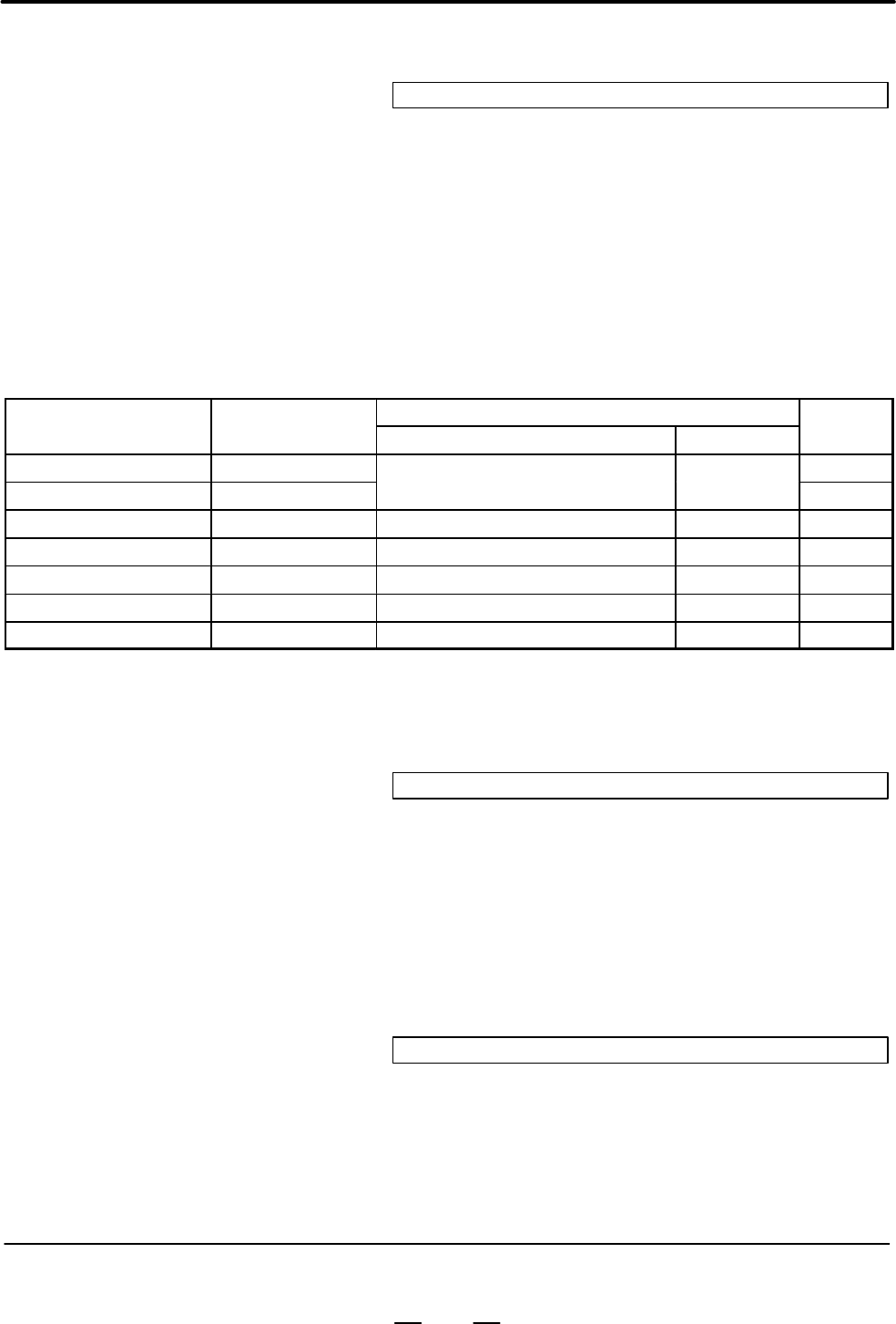
Specification
Magnetizing element
MS signal
Name
Specification
drawing No.
Type Length [mm]
MS signal
gain
No specification, standard A57L–0001–0037 0
Magnetic sensor N A57L–0001–0037/N
Standard (type II) 50
0
Magnetic sensor P A57L–0001–0037/P Small type (type III) 50 –20
Magnetic sensor Q A57L–0001–0037/Q Cylindrical, 40 in diameter (type IV) 31 70
Magnetic sensor R A57L–0001–0037/R Cylindrical, 50 in diameter (type V) 37 50
Magnetic sensor S A57L–0001–0037/S Cylindrical, 60 in diameter (type VI) 43 70
Magnetic sensor T A57L–0001–0037/T Cylindrical, 70 in diameter (type VII) 49 40
When H = 100 mm, and L = 50 mm
MS signal constant = (50/2) / (2p 100) 4096 8 163
16i/160
15 15i
MS signal gain adjustment
6579 3079 3079 4079
6719 3219
Data unit :
Data range : –128 to +127
Standard setting : 0
Use this parameter when adjusting the amplitude of the MS signal in
the magnetic sensor method orientation. Set the constant of above table
normally.
16i/160
15 15i
Motor voltage setting on orientation
6584 3084 3084 4084
6724 3224
Data unit : 1%
Data range : 0 to 100
Standard setting : Depends on the motor model
This parameter sets the motor voltage for orientation.
Example
2.3.5
Calculating the
Orientation Time
Contents Summary of AC Spindle Motor Alpha Series Parameter manual
- Page 1FANUC AC SPINDLE MOTOR α series PARAMETER MANUAL B–65160E/02 FANUC LTD, 1994
- Page 2– No part of this manual may be reproduced in any form. – All specifications and designs are subject to change without notice. In this manual we have tried as much as possible to describe all the various matters. However, we cannot describe all the matters which must not be done, or which cannot be
- Page 3B–65160E/02 DEFINITION OF WARNING, CAUTION, AND NOTE DEFINITION OF WARNING, CAUTION, AND NOTE This manual includes safety precautions for protecting the user and preventing damage to the machine. Precautions are classified into Warning and Caution according to their bearing on safety. Also, suppleme
- Page 4B–65160E/02 PREFACE PREFACE This manual describes the spindle parameters for the FANUC servo amplifier a series. Chapter 1 describes the parameters used to start normal operation. Chapter 2 describes the parameters for each function. Chapter 3 describes each spindle parameter in detail. The paramete
- Page 5PREFACE B–65160E/02 Related manuals The following six kinds of manuals are available for FANUC SERVO MOTOR α series. In the table, this manual is marked with an asterisk (*). Document Document name Major contents Major usage number D Specification FANUC AC SERVO MOTOR α series D Characteristics B–65
- Page 6B–65160E/02 Table of Contents PREFACE . . . . . . . . . . . . . . . . . . . . . . . . . . . . . . . . . . . . . . . . . . . . . . . . . . . . . . . . . . . . . . . . p–1 I. FANAC AC SPINDLE MOTOR α series 1. ADJUSTMENT . . . . . . . . . . . . . . . . . . . . . . . . . . . . . . . . . . . . . . . . .
- Page 7Table of Contents B–65160E/02 2.5.4 Detail of Parameter . . . . . . . . . . . . . . . . . . . . . . . . . . . . . . . . . . . . . . . . . . . . . . . . . . . . . . . . . . . . . . . . 109 2.5.5 Additional Information on Parameters . . . . . . . . . . . . . . . . . . . . . . . . . . . . . . . . . . .
- Page 8B–65160E/02 Table of Contents 1.3.1 The Motor Does Not Rotate . . . . . . . . . . . . . . . . . . . . . . . . . . . . . . . . . . . . . . . . . . . . . . . . . . . . . . . . . 257 1.3.2 The Motor Does Not Rotate at the Commanded Speed . . . . . . . . . . . . . . . . . . . . . . . . . . . . . . . . .
- Page 9Table of Contents B–65160E/02 C.4 SPINDLE MOTOR α L SERIES . . . . . . . . . . . . . . . . . . . . . . . . . . . . . . . . . . . . . . . . . . . . . . . . . . . . 383 C.5 SPINDLE MOTOR α HV SERIES . . . . . . . . . . . . . . . . . . . . . . . . . . . . . . . . . . . . . . . . . . . . . . . . . . 385
- Page 10I. FANUC AC SPINDLE MOTOR a series�
- Page 11
- Page 12B–65160E/02 FANUC AC SPINDLE MOTOR a series 1. ADJUSTMENT 1 ADJUSTMENT 3
- Page 131. ADJUSTMENT FANUC AC SPINDLE MOTOR a series B–65160E/02 1.1 START–UP PROCEDURE A. Check the spindle–related specifications. D CNC model D Spindle motor D Power supply module D Spindle amplifier module D Detector system B. Check all connections. (See “Connection” in the Descriptions (B–65162E).) C.
- Page 14B–65160E/02 FANUC AC SPINDLE MOTOR a series 1. ADJUSTMENT 1.2 PARAMETERS RELATED TO START–UP 1.2.1 Parameters for the a Parameter No. Series (Serial) Spindle 0 15 Description System 1st 2nd 1st 2nd 15i 16i/16 spindle spindle spindle spindle Whether to use a – – 5606 5606 5606 – series (Serial) (*1)
- Page 151. ADJUSTMENT FANUC AC SPINDLE MOTOR a series B–65160E/02 (b) When there is no model code for which the parameter data is similar, set model code 0 (or 64 when the speed range switching function is used) for automatic parameter initialization, then manually change the parameter data according to the
- Page 16B–65160E/02 FANUC AC SPINDLE MOTOR a series 1. ADJUSTMENT 1.2.3 (1) List of parameters for spindle speed commands Parameters Related to Parameter No. Description Spindle Speed 0T 0M 15 15i 16i/16 Commands Spindle speed command 0013 3706 polarity (enabled when – – #7, 6 #7, 6 input signal SSIN is set
- Page 171. ADJUSTMENT FANUC AC SPINDLE MOTOR a series B–65160E/02 0 0 Parameter No. 540 0 1 Parameter No. 541 1 0 Parameter No. 542 1 1 Parameter No. 543 (iii) The data calculated in (ii) is output to output signal: F172 (R08O to R01O) and F173 (R12O to R09O). (iv) The spindle speed data is transferred to t
- Page 18B–65160E/02 FANUC AC SPINDLE MOTOR a series 1. ADJUSTMENT Parameter No. 585 (For the maximum motor speed with the low gear) Parameter No. 586 (For the maximum motor speed with the middle gear) (ii) Sxxxxx (in min-1) is specified by the program or with the MDI. (iii) In reply to the S command, the CN
- Page 191. ADJUSTMENT FANUC AC SPINDLE MOTOR a series B–65160E/02 Theaseries (Serial) spindle allows the BMI interface only. Basically, the PMC calculates and sends the contents of the spindle motor speed command to the CNC. In general, spindle control SPCNT (machine instruction) of the PMC is used. (a) Sxx
- Page 20B–65160E/02 FANUC AC SPINDLE MOTOR a series 1. ADJUSTMENT (e) When functions such as spindle change detection and constant surface speed control are used, the following parameters are also used: Gear Maximum spindle speed (spindle speed when the maximum motor speed is specified) Gear 1 : Parameter N
- Page 211. ADJUSTMENT FANUC AC SPINDLE MOTOR a series B–65160E/02 (vi) The polarity of the speed command can be specified by SSIN (input signal ) as follows: 0: The polarity is determined by parameter Nos. 3706#7 and 3706#6, and M03 and M04. 1: The polarity is determined by the SGN (input signal) . (vii) Fo
- Page 22B–65160E/02 FANUC AC SPINDLE MOTOR a series 1. ADJUSTMENT 1: Based on the data ("4095) in input signal: G32 (R08I to R01I) and G33 (R12I to R09I), the maximum spindle speed is converted to "16384, then it is transferred to the aseries (Serial) spindle. (v) The polarity of the speed command can be sp
- Page 231. ADJUSTMENT FANUC AC SPINDLE MOTOR a series B–65160E/02 1.2.4 (1) List of parameters for detectors Parameters Related to Detectors Parameter No. Description 0T 0M 15 15i 16i/16 4000 6500 #0 3000 #0 3000 #0 Direction of spindle and motor rotation #0 6511 3011 3011 4011 Motor speed detector setting
- Page 24B–65160E/02 FANUC AC SPINDLE MOTOR a series 1. ADJUSTMENT (2) Detail of parameter for detector 0 15 15i 16i/16 #7 #6 #5 #4 #3 #2 #1 #0 1st– 6500 3000 3000 4000 DEFRTO POSC1 ROTA1 2nd– 6640 3140 ROTA1: Indicates the relationship between the rotation directions of spindle and spindle motor. 0: Rotates
- Page 251. ADJUSTMENT FANUC AC SPINDLE MOTOR a series B–65160E/02 (c) When the spindle and motor are connected by a gear with an intermediate shaft, the spindle and motor rotate in the same direction, regardless of the orientation of the spindle. The rotation directions Motor Motor of the spindle and motor
- Page 26B–65160E/02 FANUC AC SPINDLE MOTOR a series 1. ADJUSTMENT (b) When the spindle and position coder are connected by a belt as shown below, the spindle and position coder rotate in opposite directions. Motor Motor The rotation The rotation directions of the directions of the spindle and motor Belt–bas
- Page 271. ADJUSTMENT FANUC AC SPINDLE MOTOR a series B–65160E/02 (d) When the spindle and position coder are connected by a gear as shown below, the spindle and position coder rotate in the same direction. Motor Motor The rotation The rotation directions of the directions of the spindle and motor Gear–base
- Page 28B–65160E/02 FANUC AC SPINDLE MOTOR a series 1. ADJUSTMENT MGSEN:Indicates the mounting direction of magnetic sensor. 0: Rotates the motor and magnetic sensor in the same direction. 1: Rotates the motor and magnetic sensor in the reverse direction. The normal rotation command (SFRA = 1) rotates the s
- Page 291. ADJUSTMENT FANUC AC SPINDLE MOTOR a series B–65160E/02 0 15 15i 16i/16 #7 #6 #5 #4 #3 #2 #1 #0 1st– 6502 3002 3002 4002 CSDET3 CSDET2 CSDET1 2nd– 6642 3142 CSDET3-1: Cs contouring control resolution setting. (The bits of this parameter are invalid when a sensor Cs contour control function is used
- Page 30B–65160E/02 FANUC AC SPINDLE MOTOR a series 1. ADJUSTMENT PCPL2, PCPL1, PCPL0, PCTYPE: Set a position coder signal. MZ sensor, High–resolution BZ sensor PCPL2 PCPL1 PCPL0 PCTYPE magnetic Others (Built–in pulse coder sensor) Position Magnetic drum coder 256l/rev 0 0 0 0 diameter High–resolu (f103) f6
- Page 311. ADJUSTMENT FANUC AC SPINDLE MOTOR a series B–65160E/02 EXTRF: Specifies whether a reference switch signal is used. 0: Not used. 1: Used. Set this bit to 1 when a motor with a MZ sensor (built–in sensor) is used, and a one–rotation signal is obtained from a reference switch (proximity switch) moun
- Page 32B–65160E/02 FANUC AC SPINDLE MOTOR a series 1. ADJUSTMENT 0 15 15i 16i/16 #7 #6 #5 #4 #3 #2 #1 #0 1st– 6511 3011 3011 4011 VDT3 VDT2 VDT1 2nd– 6651 3151 VDT3-VDT1: Setting of speed detector VDT3 VDT2 VDT1 Setting of speed detector 0 0 0 64l/rev 0 0 1 128l/rev 0 1 0 256l/rev 0 1 1 512l/rev 1 0 0 192l
- Page 331. ADJUSTMENT FANUC AC SPINDLE MOTOR a series B–65160E/02 Detector Connector M sensor (motor) JY2 Position coder (spindle) JY4 2. Set the detector–related parameters. Parameter Setting Description 4011 #2, 1, 0 Depends on the detector. Sets a speed detector. 4003 #7, 6, 5, 4 0, 0, 0, 0 Sets a positi
- Page 34B–65160E/02 FANUC AC SPINDLE MOTOR a series 1. ADJUSTMENT (c) When a M sensor is used together with a magnetic sensor Example system configuration: M sensor Spindle amplifier Motor JY3 JY2 Spindle Magnetic sensor 1. Connect the feedback signal cables. Detector Connector M sensor (motor) JY2 Magnetic
- Page 351. ADJUSTMENT FANUC AC SPINDLE MOTOR a series B–65160E/02 2. Set the detector–related parameters. Parameter Setting Description 4004 #1 1 Uses a separate BZ sensor. 4003 #7, 6, 5, 4 Depends on the detector. Sets a position coder signal. 4011 #2, 1, 0 Depends on the detector. Sets a speed detector. 4
- Page 36B–65160E/02 FANUC AC SPINDLE MOTOR a series 1. ADJUSTMENT 1. Connect the feedback signal cable. Detector Connector High–resolution magnetic pulse coder JY5 2. Set the detector–related parameters. Parameter Setting Description 4001 #5 1 Uses a high–resolution magnetic pulse coder. 4001 #6 1 Also uses
- Page 371. ADJUSTMENT FANUC AC SPINDLE MOTOR a series B–65160E/02 (h) When a high–resolution magnetic pulse coder in a motor is used together with a high–resolution position coder Example system configuration: High–resolution magnetic pulse coder Spindle amplifier Motor TYPE 2 JY4 JY2 Preamplifier Spindle H
- Page 38B–65160E/02 FANUC AC SPINDLE MOTOR a series 1. ADJUSTMENT MZ sensor Spindle amplifier Motor TYPE 3 JY8 JY6 JY2 Main spindle M sensor Motor Sub spindle Position coder 1. Connect the feedback signal cables. Detector Connector Built–in sensor on main spindle side (motor) JY2 Pulse generator on subspind
- Page 391. ADJUSTMENT FANUC AC SPINDLE MOTOR a series B–65160E/02 Example system configuration: M sensor Spindle amplifier Motor TYPE 3 JY7 JY6 JY4 JY2 Main spindle Position coder MZ sensor Motor Sub spindle Reference switch (proximity switch) 1. Connect the feedback signal cables. Detector Connector M sens
- Page 40B–65160E/02 FANUC AC SPINDLE MOTOR a series 1. ADJUSTMENT (a) If the spindle is connected to a built–in motor or a motor incorporating an MZ sensor at a ratio of 1:1 Example system configuration 1: MZ sensor Spindle amplifier Motor TYPE 4 JY5 1:1 Spindle Example system configuration 2: BZ sensor Spi
- Page 411. ADJUSTMENT FANUC AC SPINDLE MOTOR a series B–65160E/02 MZ sensor Spindle amplifier Motor TYPE 4 JY5 JY2 Spindle BZ sensor 1. Connect the feedback signal cables. Detector Connector MZ sensor (motor) JY2 BZ sensor (spindle) JY5 2. Set the detector–related parameters. Parameter Setting Description 4
- Page 42B–65160E/02 FANUC AC SPINDLE MOTOR a series 1. ADJUSTMENT 1. Connect the feedback signal cables. Detector Connector MZ sensor (motor) JY2 a position coder S (spindle) JY5 2. Set the detector–related parameters. Parameter Setting Description 4018#4 1 Uses the a sensor Cs contouring control function.
- Page 431. ADJUSTMENT FANUC AC SPINDLE MOTOR a series B–65160E/02 (2) Details of parameters related to normal operation mode 0 15 15i 16i/16 1st– 6540 3040 3040 4040 Velocity loop proportion gain on normal operation (HIGH gear) CTHIA=0 2nd– 6680 3180 1st– 6541 3041 3041 4041 Velocity loop proportion gain on
- Page 44B–65160E/02 FANUC AC SPINDLE MOTOR a series 1. ADJUSTMENT 1.3 If the spindle motor malfunctions, correct the fault as specified in the table below. Refer to the maintenance manual for an explanation of the PARAMETER response required when an alarm occurs. ADJUSTMENT Symptom Relevant section 1 The mo
- Page 451. ADJUSTMENT FANUC AC SPINDLE MOTOR a series B–65160E/02 1.3.2 (1) Check all connections. (See the description of the connections.) When the Motor Does (a) Motor power line connection Not Rotate at the (b) Feedback signal cable connection Commanded Speed (2) Check the parameter settings. (a) Parame
- Page 46B–65160E/02 FANUC AC SPINDLE MOTOR a series 1. ADJUSTMENT (3) Compare the conditions when the motor is driven and when the motor is coasting. If considerably less vibration and noise is observed while the motor is coasting, the control circuitry is faulty. If the same degree of vibration and noise i
- Page 471. ADJUSTMENT FANUC AC SPINDLE MOTOR a series B–65160E/02 1.3.6 (1) Check the parameter settings. When Time Required (a) Parameter data for each motor model (See Appendix C.) for Acceleration/ (b) Limited output pattern and output limit Deceleration Increases 0 15 15i 16i/16 Description 6528 3028 30
- Page 48B–65160E/02 FANUC AC SPINDLE MOTOR a series 1. ADJUSTMENT Indication Status error Action 01 SFR (normal rotation command), SRV (reverse Check the sequence of *ESP and MRDY. For rotation command), or ORCM (orientation MRDY, check bit 0 of parameter No. 4001, command) is entered when *ESP (emergency s
- Page 491. ADJUSTMENT FANUC AC SPINDLE MOTOR a series B–65160E/02 Indication Status error Action 13 When the orientation command is entered, another When orientation is specified, do not specify mode (Cs contouring control, servo mode, or another mode. To enter another mode, first cancel spindle synchroniza
- Page 50B–65160E/02 FANUC AC SPINDLE MOTOR a series 2. FUNCTION EXPLANATION 2 FUNCTION EXPLANATION 41
- Page 512. FUNCTION EXPLANATION FANUC AC SPINDLE MOTOR a series B–65160E/02 2.1 POSITION CODER METHOD SPINDLE ORIENTATION 2.1.1 Start–up Procedure A. Check that normal operation can be performed. B. Prepare and check the ladder program for spindle orientation. (Refer to the descriptions.) C. Set the paramet
- Page 52B–65160E/02 FANUC AC SPINDLE MOTOR a series 2. FUNCTION EXPLANATION J. Adjust the orientation stop (to eliminate overshoot and ensure stop–time rigidity). D Position gain for orientation D Velocity loop proportional gain for orientation D Velocity loop integral gain for orientation D Motor voltage f
- Page 532. FUNCTION EXPLANATION FANUC AC SPINDLE MOTOR a series B–65160E/02 2.1.3 Parameters Related to Position Coder Method Spindle Orientation Parameter No. Description 0 15 15i 16i/16 6515 #0 3015 #0 3015 #0 4015 #0 Specifies whether to use the spindle orientation function. (Set this bit to 1.) (The CNC
- Page 54B–65160E/02 FANUC AC SPINDLE MOTOR a series 2. FUNCTION EXPLANATION Parameter No. Description 0 15 15i 16i/16 6292 3472 3328 4328 Command multiplication with an externally set incremental command 6294 3474 3330 4330 Motor activation delay for spindle orientation 6509 #3 3009 #3 3009 #3 4009 #3 Arbit
- Page 552. FUNCTION EXPLANATION FANUC AC SPINDLE MOTOR a series B–65160E/02 Parameter No. Description 0 15 15i 16i/16 6288 3468 3324 4324 Shortest–time orientation deceleration constant 6289 3469 3325 4325 (A parameter is selected by the CTH1A input signal.) 6291 3471 3327 4327 Pulse width for shortest–time
- Page 56B–65160E/02 FANUC AC SPINDLE MOTOR a series 2. FUNCTION EXPLANATION DIRCT2-DIRCT1: Setting of rotation direction at spindle orientation DIRCT2 DIRCT1 Rotation direction at spindle orientation 0 0 By rotation direction immediately before (It is CCW at the power on.) 0 1 By rotation direction immediat
- Page 572. FUNCTION EXPLANATION FANUC AC SPINDLE MOTOR a series B–65160E/02 Setting this bit to 1 reduces the time required for orientation by a position coder immediately after the spindle speed exceeds the maximum position coder signal detection speed (set in parameter No. 4098). NRROEN: Specifies whether
- Page 58B–65160E/02 FANUC AC SPINDLE MOTOR a series 2. FUNCTION EXPLANATION 0 15 15i 16i/16 1st– 6542 3042 3042 4042 Velocity loop proportion gain on orientation (HIGH gear) CTH1A=0 2nd– 6682 3182 1st– 6543 3043 3043 4043 Velocity loop proportion gain on orientation (LOW gear) CTH1A=1 2nd– 6683 3183 Data un
- Page 592. FUNCTION EXPLANATION FANUC AC SPINDLE MOTOR a series B–65160E/02 These parameters set the gear ratio of the spindle motor relative to the spindle. When the motor rotates 2.5 times, for every rotation of the spindle, for example, set 250 in the parameter. A parameter is selected by the CTH1A and C
- Page 60B–65160E/02 FANUC AC SPINDLE MOTOR a series 2. FUNCTION EXPLANATION Standard setting : 10 This data is used to set the detecting level of orientation completion signal (ORARA). When the spindle position is located within the setting data on orientation completion, the bit of orientation completion s
- Page 612. FUNCTION EXPLANATION FANUC AC SPINDLE MOTOR a series B–65160E/02 0 15 15i 16i/16 1st– 6598 3098 3098 4098 Maximum speed of position coder signal detection 2nd– 6738 3238 Data unit : 1min–1 (When parameter No. 4006 #1 (GRUNIT) =1, 10min–1) Data range : 0 to 32767 Standard setting : 0 Parameter for
- Page 62B–65160E/02 FANUC AC SPINDLE MOTOR a series 2. FUNCTION EXPLANATION 0 15 15i 16i/16 1st– 6284 3464 3320 4320 Spindle orientation deceleration constant (HIGH) 2nd– 6464 3684 CTH1A=0, CTH2A=0 1st– 6285 3465 3321 4321 Spindle orientation deceleration constant (MEDIUM HIGH) 2nd– 6465 3685 CTH1A=0, CTH2A
- Page 632. FUNCTION EXPLANATION FANUC AC SPINDLE MOTOR a series B–65160E/02 An approximate value for Nb/Tb can be calculated as follows: Nb + Tm 60 Tb Jm ) Jl 2p where, Tm : 30–min rated torque [Nm] Jm + Jl : Rotor inertia + load inertia [kg m2] 0 15 15i 16i/16 1st– 6290 3470 3326 4326 Spindle orientation c
- Page 64B–65160E/02 FANUC AC SPINDLE MOTOR a series 2. FUNCTION EXPLANATION When spindle orientation is started when the speed is within the range between the zero speed detection level and the orientation speed, overshoot may occur upon orientation stop. This may be prevented by specifying 50 msec or more
- Page 652. FUNCTION EXPLANATION FANUC AC SPINDLE MOTOR a series B–65160E/02 2.1.6 Adjusting the Adjust the orientation stop position shift parameter by following the Orientation Stop procedure below. Position Shift (1) Specify parameters as follows: Parameter Bit 7 of parameter No. 4016 = 0 Parameter No. 40
- Page 66B–65160E/02 FANUC AC SPINDLE MOTOR a series 2. FUNCTION EXPLANATION 2.1.7 Calculating the The time required for orientation differs between the first orientation Orientation Time (before the position coder one–rotation signal has first been detected) and the second and subsequent orientations (once
- Page 672. FUNCTION EXPLANATION FANUC AC SPINDLE MOTOR a series B–65160E/02 (c) t3 is the time required for the motor to rotate zero to one turns at orientation speed Nori [min–1]. 0 60 Nori x t3 x 1 60 Nori N 0 x t3 x 1 PG Rori (d) t4 is the time from the start of deceleration until orientation has been co
- Page 68B–65160E/02 FANUC AC SPINDLE MOTOR a series 2. FUNCTION EXPLANATION 2.2 HIGH–SPEED ORIENTATION 2.2.1 Procedure for Setting 1) Specify bit parameters (including position coder setting). Parameters 2) Specify the orientation stop position. D No. 4077: Orientation stop position shift value D No. 4031:
- Page 692. FUNCTION EXPLANATION FANUC AC SPINDLE MOTOR a series B–65160E/02 Parameter No. Description 0 15 15i 16i/16 6515 #0 3015 #0 3015 #0 4015 #0 Spindle orientation function (Specify 1.) 0080 5609 5609 2 3702 Spindle orientation function of stop position external setting type #3, 2 #3, 2 #3, 2 (#2: Fir
- Page 70B–65160E/02 FANUC AC SPINDLE MOTOR a series 2. FUNCTION EXPLANATION 0 15 15i 16i/16 #7 #6 #5 #4 #3 #2 #1 #0 6518 3018 3018 4018 HSORI HSVCM HSVCM:Velocity command correction at high–speed orientation 0: Not provided 1: Provided Usually, specify : 0 HSORI: High–speed orientation function 0: Disabled
- Page 712. FUNCTION EXPLANATION FANUC AC SPINDLE MOTOR a series B–65160E/02 DIRCT2-DIRCT1: Rotation direction at orientation DIRCT2 DIRCT1 Rotation direction Depends on the previous rotation direction 0 0 (counterclockwise for the first rotation after power–up) Depends on the previous rotation direction (cl
- Page 72B–65160E/02 FANUC AC SPINDLE MOTOR a series 2. FUNCTION EXPLANATION 0 15 15i 16i/16 6531 3031 3031 4031 Position coder method orientation stop position Data unit : 1 pulse (360 degrees/4096) Data range : 0 to 4096 Standard setting : 0 This parameter specifies the stop position of position coder meth
- Page 732. FUNCTION EXPLANATION FANUC AC SPINDLE MOTOR a series B–65160E/02 0 15 15i 16i/16 6556 3056 3056 4056 Gear ratio (HIGH) CTH1A=0, CTH2A=0 6557 3057 3057 4057 Gear ratio (MEDIUM HIGH) CTH1A=0, CTH2A=1 6558 3058 3058 4058 Gear ratio (MEDIUM LOW) CTH1A=1, CTH2A=0 6559 3059 3059 4059 Gear ratio (LOW) C
- Page 74B–65160E/02 FANUC AC SPINDLE MOTOR a series 2. FUNCTION EXPLANATION This parameter specifies the detection level of orientation completion signal (ORARA) which is a DO signal. If the positional deviation falls within the specified range, ORARA goes 1. 0 15 15i 16i/16 6577 3077 3077 4077 Orientation
- Page 752. FUNCTION EXPLANATION FANUC AC SPINDLE MOTOR a series B–65160E/02 The parameter settings are given as follows: Deceleration time constant + t 60 (0.8 to 0.9) J 2p where τ (Nm) : Maximum motor torque at upper limit of orientation speed (No. 4038) J (kgm2) : Motor inertia + Load inertia 0 15 15i 16i
- Page 76B–65160E/02 FANUC AC SPINDLE MOTOR a series 2. FUNCTION EXPLANATION 2.3 MAGNETIC SENSOR METHOD SPINDLE ORIENTATION 67
- Page 772. FUNCTION EXPLANATION FANUC AC SPINDLE MOTOR a series B–65160E/02 2.3.1 Start–up Procedure A. Check that the system is ready for normal operation. B. Prepare and check the ladder program for performing magnetic sensor method orientation. B. (Refer to the Descriptions (B–65162E).) C. Set the necess
- Page 78B–65160E/02 FANUC AC SPINDLE MOTOR a series 2. FUNCTION EXPLANATION 2.3.2 Spindle Control (1) Input signals (PMC to CNC) Signals 0 15 15i 16i/16 #7 #6 #5 #4 #3 #2 #1 #0 1st– G229 G227 G227 G070 MRDYA ORCMA SFRA SRVA CTH1A CTH2A TLMHA TLMLA 2nd– G233 G235 G235 G07 1st– G230 G226 G226 G071 RCHA RSLA I
- Page 792. FUNCTION EXPLANATION FANUC AC SPINDLE MOTOR a series B–65160E/02 Parameters on the sub spindle side of spindle switching control Parameter No. Description 0 15 15i 16i/16 6141 #2 3321 #2 3177 #3 4177 #3 Mounting direction of the magnetic sensor 6140 #0 3320 #0 3176 #0 4176 #0 Direction of spindle
- Page 80B–65160E/02 FANUC AC SPINDLE MOTOR a series 2. FUNCTION EXPLANATION 0 15 15i 16i/16 #7 #6 #5 #4 #3 #2 #1 #0 1st– 6503 3003 3003 4003 DIRCT2 DIRCT1 PCMGSL 2nd– 6643 3143 Standard setting: 0 0 0 0 0 0 0 1 PCMGSL: Selection of rotation direction on spindle orientation set to ”1” (Magnetic sensor). DIRC
- Page 812. FUNCTION EXPLANATION FANUC AC SPINDLE MOTOR a series B–65160E/02 0 15 15i 16i/16 1st– 6542 3042 3042 4042 Velocity loop proportion gain on orientation (HIGH gear) CTH1A=0 2nd– 6682 3182 1st– 6543 3043 3043 4043 Velocity loop proportion gain on orientation (LOW gear) CTH1A=1 2nd– 6683 3183 Data un
- Page 82B–65160E/02 FANUC AC SPINDLE MOTOR a series 2. FUNCTION EXPLANATION 0 15 15i 16i/16 1st– 6556 3056 3056 4056 Gear ratio (HIGH) CTH1A=0, CTH2A=0 2nd– 6696 3196 1st– 6557 3057 3057 4057 Gear ratio (MEDIUM HIGH) CTH1A=0, CTH2A=1 2nd– 6697 3197 1st– 6558 3058 3058 4058 Gear ratio (MEDIUM LOW) CTH1A=1, C
- Page 832. FUNCTION EXPLANATION FANUC AC SPINDLE MOTOR a series B–65160E/02 1st– 6575 3075 3075 4075 Orientation completion signal detection level 2nd– 6715 3215 Data unit : Position coder method → "1 pulse unit Magnetic sensor method → "0.1 degree unit Data range : 0 to 100 Standard setting : 10 This data
- Page 84B–65160E/02 FANUC AC SPINDLE MOTOR a series 2. FUNCTION EXPLANATION 0 15 15i 16i/16 6578 3078 3078 4078 MS signal constant = (L/2)/(2 p H) 4096 6718 3218 L: Length of magnetizing element (mm) H: Distance from spindle center to magnetizing element (mm) Data unit : Data range : 80 to 1000 Standard set
- Page 852. FUNCTION EXPLANATION FANUC AC SPINDLE MOTOR a series B–65160E/02 (1) Calculating the orientation time In the following explanation, the time, from the input of an orientation command until orientation stops, is divided into five periods. In the following figure, A indicates that the motor in the
- Page 86B–65160E/02 FANUC AC SPINDLE MOTOR a series 2. FUNCTION EXPLANATION (d) Speed Nms [min–1] is calculated as follows: Nms + L 1 60 PG 2 2pH where, L : Length of the magnetizing element [mm] H : Distance from the center of the spindle to the magnetizing element [mm] t4 is the time required to rotate (L
- Page 872. FUNCTION EXPLANATION FANUC AC SPINDLE MOTOR a series B–65160E/02 2.4 RIGID TAPPING 2.4.1 Start–up Procedure A. Check that normal operation is possible. B. Prepare and check the rigid tapping ladder program. (See Section 2.4.2.) C. Set up the detector–related parameters according to the system con
- Page 88B–65160E/02 FANUC AC SPINDLE MOTOR a series 2. FUNCTION EXPLANATION 2.4.2 Spindle Control (1) Input signals (PMC³CNC) Signals Relating (a) Series 0 to Rigid Tapping 0TT #7 #6 #5 #4 #3 #2 #1 #0 HEAD2 G118 G1318 GR2 GR1 (*1) (*1) G123 G1323 GR2 GR1 RGTPN (*2) (*2) (*3) G135 G1335 RGTAP (*4) G145 G1345
- Page 892. FUNCTION EXPLANATION FANUC AC SPINDLE MOTOR a series B–65160E/02 (c) Series 16/18 TT– #7 #6 #5 #4 #3 #2 #1 #0 HEAD2 G028 G1028 GR2 GR1 G061 G1061 RGTAP G027 G1027 SWS2 SWS1 (*1) (*1) G029 G1029 GR21 (*2) G070 G1070 SFRA CTH1A CTH2A (*1) The rigid tapping of the second spindle is available by the
- Page 90B–65160E/02 FANUC AC SPINDLE MOTOR a series 2. FUNCTION EXPLANATION 2.4.3 Rigid Tapping Parameter Table Parameter number 0M/T/TT 16i/16 Remarks 15M/T 15ii Fst. sp Snd. sp M/T/TT 0256 – – 5210 M code of rigid tapping command 0031 #5 (T) – – – Address selection of gear signal 0019 #4 (M) – – – Input s
- Page 912. FUNCTION EXPLANATION FANUC AC SPINDLE MOTOR a series B–65160E/02 Parameter number 0M/T/TT 16i/16 Remarks 15M/T 15i Fst. sp Snd. sp M/T/TT Parameter number OM/T/TT 16i/16 Remarks 15M/T 15ii Fst. sp Snd. sp M/T/TT (M) (T) 5605 #2 5605 #2 5241 Spindle maximum speed at rigid tapping 0617 0423 5757 57
- Page 92B–65160E/02 FANUC AC SPINDLE MOTOR a series 2. FUNCTION EXPLANATION 2.4.4 (1) Set the parameter “Position coder signal is used” Detail of Parameter for The parameter setting address is as follows. Rigid Tapping 0 0 15 15i 16i/16 Setting T/M/TT T/TT T/M T/M/TT data Fst. sp Snd. sp 6501 #2 6641 #2 300
- Page 932. FUNCTION EXPLANATION FANUC AC SPINDLE MOTOR a series B–65160E/02 (6) Parameter setting relating to the system in which the MZ sensor or BZ sensor is used. When rigid tapping is to be performed using a MZ sensor or BZ sensor, or when a built–in motor with a BZ sensor is being used, the following p
- Page 94B–65160E/02 FANUC AC SPINDLE MOTOR a series 2. FUNCTION EXPLANATION Standard machining [M series] Gear signal Parameter NO GR1O GR2O GR3O 1 0 0 663 0 1 0 664 0 0 1 665 Turning [T/TT series] and maching [M series] with surface speed constant Gear selection signal Parameter NO Fst. sp Snd. sp GR1 GR2
- Page 952. FUNCTION EXPLANATION FANUC AC SPINDLE MOTOR a series B–65160E/02 Series 15 (a) Only one arbitrary gear ratio parameter is valid in case of 5604#1=1, 5604#2=0. Parameter NO Gear teeth number of spindle side 5703 Gear teeth number of position coder side 5704 (b) Four kinds of arbitrary gear ratio p
- Page 96B–65160E/02 FANUC AC SPINDLE MOTOR a series 2. FUNCTION EXPLANATION Turning [T/TT series] and maching [M series] with surface speed constant Gear selection signal Parameter NO Fst. sp Snd. sp GR1 GR2 GR21 T/TT M 0 0 0 5221 1 0 1 5222 0 1 –– 5223 1 1 –– 5224 5223 D Set the gear teeth number of the po
- Page 972. FUNCTION EXPLANATION FANUC AC SPINDLE MOTOR a series B–65160E/02 Gear signal Parameter number CTH1A CTH2A 0M/T/TT 15M/T 15i 16(18)T/M/ Fst.sp TT Fst. sp 0 0 6556 3056 3056 4056 (S1) 0 1 6557 3057 3057 4057 (S1) 1 0 6558 3058 3058 4058 (S1) 1 1 6559 3059 3059 4059 (S1) [0T/TT Snd. sp, 16 (18) T/TT
- Page 98B–65160E/02 FANUC AC SPINDLE MOTOR a series 2. FUNCTION EXPLANATION Gear selection signal Parameter NO Fst. sp Snd. sp GR1 GR2 GR21 T/TT M (*1) 406 615 0 0 0 407 669 1 0 1 408 670 0 1 409 671 1 1 410 (*1) When this parameter is “0”, each gear parameter becomes valid. When this parameter is not “0”,
- Page 992. FUNCTION EXPLANATION FANUC AC SPINDLE MOTOR a series B–65160E/02 (c) In case of Series 15 In the rigid tapping, the same parameter address data is used for the position gain of the tapping axis and the spindle. Each position gain is selected as follows according to the gear selection signal (CTH1
- Page 100B–65160E/02 FANUC AC SPINDLE MOTOR a series 2. FUNCTION EXPLANATION Turning [T/TT series] and maching [M series] with surface speed constant Gear selection signal Parameter NO Fst. sp Snd. sp GR1 GR2 GR21 T/TT M 5280 (*1) 0 0 0 5281 1 0 1 5282 0 1 –– 5283 1 1 –– 5284 5283 (*1) When this parameter is
- Page 1012. FUNCTION EXPLANATION FANUC AC SPINDLE MOTOR a series B–65160E/02 (9) Parameter setting relating to ”acceleration/deceleration time constant” and ”maximum spindle rotation speed for rigid tapping” (a) How to determine the acceleration/deceleration time constant (b) In case of Series 0 i) Set the s
- Page 102B–65160E/02 FANUC AC SPINDLE MOTOR a series 2. FUNCTION EXPLANATION [Machining system (M series)] Each gear time constant becomes valid by setting the parameter below. 0077 #1 0 : the same time constant for all gear 1 : each time constant for each gear By setting the following parameter, the differe
- Page 1032. FUNCTION EXPLANATION FANUC AC SPINDLE MOTOR a series B–65160E/02 Gear selection signal Time constant Time constant Rigid tapping spindle Fst. sp Snd. sp (Cutting in) (Cutting out) max. speed Parameter NO Parameter NO Parameter NO GR1 GR2 GR21 0 0 0 415 419 423 1 0 1 416 420 424 0 1 417 421 425 1
- Page 104B–65160E/02 FANUC AC SPINDLE MOTOR a series 2. FUNCTION EXPLANATION Gear 2 5758 5762 Gear 3 5759 5764 (d) Series 15i i) Acc/Dec type 5605 #1 0 : Exponential type 1 : Linear type Acc/Dec (Standard setting) ii) Set Acc/Dec the time constant of the rigid tapping mode. D The time constant is a fixed val
- Page 1052. FUNCTION EXPLANATION FANUC AC SPINDLE MOTOR a series B–65160E/02 Gear selection signal Spindle max. speed Time constant Time constant Parameter NO Fst. sp Snd. sp (Cutting in) (Cutting out) Parameter NO Parameter NO Turning Machining GR1 GR2 GR21 (T/TTseries) (M series) 0 0 0 5261 5271 5241 5241
- Page 106B–65160E/02 FANUC AC SPINDLE MOTOR a series 2. FUNCTION EXPLANATION (b) SetHThe delay time until the motor excitation becomes stableI. Set the time required to observe the stable motor excitation state after switching to the rigid tapping mode. Set a value from 250 to 400 in the parameter. The param
- Page 1072. FUNCTION EXPLANATION FANUC AC SPINDLE MOTOR a series B–65160E/02 (b) In case of Series 15 Set the backlash data according to the following bit paramter. 5604 #2 0 : The same parameter is applied for all gear. The address is NO. 5756. 1 : Each parameter for each gear is set according to the gear s
- Page 108B–65160E/02 FANUC AC SPINDLE MOTOR a series 2. FUNCTION EXPLANATION 2.4.5 Adjustment Procedure (1) Parameters used for adjustment The table below lists and describes the parameters used for adjusting rigid tapping. Parameter No. Description 5241 to 5244 Maximum spindle speed in rigid tapping (Depend
- Page 1092. FUNCTION EXPLANATION FANUC AC SPINDLE MOTOR a series B–65160E/02 (2) Observing data used for adjustment In rigid tapping, adjust the parameters while observing the motor speed, torque command, velocity deviation, synchronization error, and other data by using a spindle check board and oscilloscop
- Page 110B–65160E/02 FANUC AC SPINDLE MOTOR a series 2. FUNCTION EXPLANATION Nr: Maximum rigid tapping speed (Nos. 5241 to 5244) 4000 min–1 in this example ta: Time of acceleration by the maximum torque at Nr About 400 ms in this example Motor speed tr: Rigid tapping acceleration/deceleration time constant (
- Page 1112. FUNCTION EXPLANATION FANUC AC SPINDLE MOTOR a series B–65160E/02 2. Specifying a position gain Specify an initial value of about 2000 (20 sec–1) to 3000 (30 sec–1), then adjust the value as needed. Basically, specify identical values for the spindle and tapping axis. After specifying the position
- Page 112B–65160E/02 FANUC AC SPINDLE MOTOR a series 2. FUNCTION EXPLANATION 4. Specifying an acceleration/deceleration time constant (2): Specifying an optimum value Observing the torque command and motor speed, make a final adjustment of the time constant. Adjust the time constant in consideration of the a
- Page 1132. FUNCTION EXPLANATION FANUC AC SPINDLE MOTOR a series B–65160E/02 2.4.6 Diagnosis (1) In case of Series 0 Diagnosis number Contents Machining Turning unit Mchining Turning (M series) (T series) 0800 0800 Position error of X axis Position error of X axis pulse 0801 0801 Position error of Y axis Pos
- Page 114B–65160E/02 FANUC AC SPINDLE MOTOR a series 2. FUNCTION EXPLANATION 2.4.7 Alarm (1) Program error (P/S Alarm) (a) In case of Series 0, Series 16i/ 16 Alarm number Contents 200 S command is over the range or not inputted. 201 F command is not inputted. 202 The interpolation pulse for the spindle is o
- Page 1152. FUNCTION EXPLANATION FANUC AC SPINDLE MOTOR a series B–65160E/02 2.5 CS CONTOURING CONTROL 2.5.1 Start–up Procedure A. Check that the system is ready to start normal operation. B. Prepare and check the ladder program for the Cs contouring control B. function. (Refer to the Descriptions (B–65162E)
- Page 116B–65160E/02 FANUC AC SPINDLE MOTOR a series 2. FUNCTION EXPLANATION (1) Input signal (PMC to CNC) 0 15 15i 16i/16 #7 #6 #5 #4 #3 #2 #1 #0 G123 CON COFF (M) (T) G027 CON (T/M) G67, 71..G67, 71.. G229 G227 G070 MRDYA ORCMA SFRA SRVA CTH1A CTH2A TLMHA TLMLA G230 G226 G071 RCHA RSLA INTGA SOCNA MCFNA SP
- Page 1172. FUNCTION EXPLANATION FANUC AC SPINDLE MOTOR a series B–65160E/02 Parameter No. Description 0T 0M 15 15i 16i/16 0595 0596 1829 5881 1829 Position error limit when stopped – – 1830 5882 – Position error limit when the servo system is off 0332 0333 1832 – 1832 Position error limit at feed stop 0520
- Page 118B–65160E/02 FANUC AC SPINDLE MOTOR a series 2. FUNCTION EXPLANATION Parameter Description 0 15 15i 16i/16 6599 3099 3099 4099 Motor excitation delay 6635 3135 3135 4135 Grid shift in Cs contouring control mode Parameters related to detector when the a sensor Cs contouring control function is used Pa
- Page 1192. FUNCTION EXPLANATION FANUC AC SPINDLE MOTOR a series B–65160E/02 0 15 15i 16i/16 #7 #6 #5 #4 #3 #2 #1 #0 6501 3001 3001 4001 CAXIS3 CAXIS2 CAXIS1 CAXIS1:Determines whether the high-resolution magnetic pulse coder is used or not. 0: Not used. 1: Used. (Set to 1) Set to 1 if high–resolution positio
- Page 120B–65160E/02 FANUC AC SPINDLE MOTOR a series 2. FUNCTION EXPLANATION 0: Rotation direction function enabled When bit 1 (ROTA2) of parameter No. 4000 is 0 With a + motion command, the spindle rotates counterclockwise when SFR = 1, and the spindle rotates clockwise when SRV = 1. When bit 1 (ROTA2) of p
- Page 1212. FUNCTION EXPLANATION FANUC AC SPINDLE MOTOR a series B–65160E/02 0 15 15i 16i/16 #7 #6 #5 #4 #3 #2 #1 #0 6519 3019 3019 4019 DTTMCS DTTMCS: Specifies whether to apply dead zone compensation in Cs contouring control. 0: Does not apply dead zone compensation. 1: Applies dead zone compensation. 0 15
- Page 122B–65160E/02 FANUC AC SPINDLE MOTOR a series 2. FUNCTION EXPLANATION 6547 3047 3047 4047 Velocity loop proportion gain in Cs contouring control (LOW gear) CTH1A=1 Standard setting : 30 These parameters specify the proportional gains of the velocity loop in Cs contouring control mode. A parameter is s
- Page 1232. FUNCTION EXPLANATION FANUC AC SPINDLE MOTOR a series B–65160E/02 When the motor rotates 2.5 times for every rotation of the spindle, for example, set 250 in the parameter. A parameter is selected by the CTH1A and CTH2A input signals. The gear or clutch status must correspond to the status of the
- Page 124B–65160E/02 FANUC AC SPINDLE MOTOR a series 2. FUNCTION EXPLANATION 0 15 15i 16i/16 6574 3074 3074 4074 Speed for return to reference position in Cs contouring control/servo mode Data unit : 1 min–1 Data range : 0 to 32767 Standard setting : 0 When this parameter is set to 0 In returning to the refe
- Page 1252. FUNCTION EXPLANATION FANUC AC SPINDLE MOTOR a series B–65160E/02 0 15 15i 16i/16 6594 3094 3094 4094 The constant of the torque disturbance compensating (Acceleration feedback gain) Data unit : Data range : 0 to 32767 Standard setting : 0 This parameter specifies the constant for compensating for
- Page 126B–65160E/02 FANUC AC SPINDLE MOTOR a series 2. FUNCTION EXPLANATION 0 15 15i 16i/16 6635 3135 3135 4135 Grid shift amount in Cs contouring control Data unit : Number of pulses (0.001 degrees) Data range : – 360000 to +360000 Standard setting : 0 Set the pulse from one rotation signal to machine zero
- Page 1272. FUNCTION EXPLANATION FANUC AC SPINDLE MOTOR a series B–65160E/02 0 15 15i 16i/16 #7 #6 #5 #4 #3 #2 #1 #0 6511 3011 3011 4011 VDT3 VDT2 VDT1 VDT3, VDT2, VDT1: Speed detector type Specify these bits according to the speed detector type. 0 15 15i 16i/16 #7 #6 #5 #4 #3 #2 #1 #0 6518 3018 3018 4018 AS
- Page 128B–65160E/02 FANUC AC SPINDLE MOTOR a series 2. FUNCTION EXPLANATION 2.5.5 Additional Information (1) Time constant for rapid feed along axes subject to Cs contouring on Parameters control Parameter No. Description 0T 0M 15 15i 16i/16 Linear acceleration/ deceleration time 0524 0525 1620 – 1620 const
- Page 1292. FUNCTION EXPLANATION FANUC AC SPINDLE MOTOR a series B–65160E/02 T series Control axis No. Axis name Servo axis No. 1 X 1 2 Z 2 3 C 3 4 4th 4 M series Control axis No. Axis name Servo axis No. 1 X 1 2 Y 2 3 Z 3 4 C 4 (2) Gear selection signals (CTH1A, CTH2A) The gear selection signals are used to
- Page 130B–65160E/02 FANUC AC SPINDLE MOTOR a series 2. FUNCTION EXPLANATION Set parameter Nos. 6780 to 6783 to the same value as parameter Nos. 6569 to 6772. Gear selection signal Cs contouring Common to all control axis CTH1 CTH2 servo axes (spindle) 0 0 6780 6569 0 1 6781 6570 1 0 6782 6571 1 1 6783 6572
- Page 1312. FUNCTION EXPLANATION FANUC AC SPINDLE MOTOR a series B–65160E/02 After switching to the Cs contouring control mode, the reference position return mode is entered by setting the ZRN signal to ON. One of the feed axis selection signals –3 and +3 (for the T series or – 4 and +4 (for the M series) is
- Page 132B–65160E/02 FANUC AC SPINDLE MOTOR a series 2. FUNCTION EXPLANATION PRM No. 65 CZRN=1 If the G00 command is executed when the machine has not returned to the reference position since switching to the Cs contouring control mode, the serial spindle performs normal positioning from its stopped position
- Page 1332. FUNCTION EXPLANATION FANUC AC SPINDLE MOTOR a series B–65160E/02 (5) Others (a) Switching between the spindle rotation control and Cs contouring control modes during automatic operation When switching between the spindle rotation control and Cs contouring control modes is performed during an auto
- Page 134B–65160E/02 FANUC AC SPINDLE MOTOR a series 2. FUNCTION EXPLANATION 2.5.8 Additional Description of Series 15 (1) Axis arrangement in the Cs contouring control mode (a) The same number as the control axis number must be set for the servo axis number of the axis for which Cs contouring control is per
- Page 1352. FUNCTION EXPLANATION FANUC AC SPINDLE MOTOR a series B–65160E/02 Parameter No. #7 #6 #5 #4 #3 #2 #1 #0 5609 NGC2 NGC1 NGC1: Specifies whether to set the position gain of the servo axes other than the Cs contouring control axis (1st spindle) to the same value as the position gain of the Cs contour
- Page 136B–65160E/02 FANUC AC SPINDLE MOTOR a series 2. FUNCTION EXPLANATION (d) When the gain is not changed If there is no interpolation between the Cs contouring control axis and other axes, or if the Cs contouring control axis and servo axes have the same position gain, the gain need not be changed. In t
- Page 1372. FUNCTION EXPLANATION FANUC AC SPINDLE MOTOR a series B–65160E/02 If the G00 command is executed when the machine has not returned to the reference position since switching to the Cs contouring control mode, aseries (Serial) spindle performs normal positioning from its stopped position. In this ca
- Page 138B–65160E/02 FANUC AC SPINDLE MOTOR a series 2. FUNCTION EXPLANATION (5) Others (a) Switching from the Cs contouring control mode to the spindle rotation control mode Before changing the modes, be sure to confirm that the motion command for the spindle in automatic or manual operation has terminated.
- Page 1392. FUNCTION EXPLANATION FANUC AC SPINDLE MOTOR a series B–65160E/02 2.6 SPINDLE SYNCHRONIZATION CONTROL 2.6.1 Start–up Procedure A. Check that normal operation can be performed. B. Prepare and check the ladder programs for the spindle synchronization function. (Refer to the Descriptions (B–65162E).)
- Page 140B–65160E/02 FANUC AC SPINDLE MOTOR a series 2. FUNCTION EXPLANATION 2.6.2 DI/DO Signals Related to Spindle (1) Input signals (PMC ³ CNC) Synchronization 0T 0TT 15 16i/16 #7 #6 #5 #4 #3 #2 #1 #0 G146 G146 G038 SPPHS SPSYC G124 G124 G032 R081 R071 R061 R051 R041 R031 R021 R011 G125 G125 G033 SSGN R121
- Page 1412. FUNCTION EXPLANATION FANUC AC SPINDLE MOTOR a series B–65160E/02 Parameter No. 0T 15TT Description 0TT 16i/16 1st 2nd 1st 2nd Error pulse difference between the two spindles for 0576 0576 5811 4811 issuing an alarm while spindle synchronization is applied Acceleration/deceleration time constant u
- Page 142B–65160E/02 FANUC AC SPINDLE MOTOR a series 2. FUNCTION EXPLANATION 2.6.4 Parameter Detail for Spindle Synchronization Control 0 15 15i 16i/16 #7 #6 #5 #4 #3 #2 #1 #0 1st– 6500 3000 4000 POSC1 ROTA1 2nd– 6640 3140 ROTA1: Indicates the relationship between the rotation directions of spindle and spind
- Page 1432. FUNCTION EXPLANATION FANUC AC SPINDLE MOTOR a series B–65160E/02 Parameter No. Series 0T Series 15TT Series Description 0TT 1st 2nd 1st 2nd 16i/16 6556 6696 6556 3056 3196 4056 Gear ratio 6557 6697 6557 3057 3197 4057 6558 6698 6558 3058 3198 4058 6559 6699 6559 3059 3199 4059 SYCREF: Setting for
- Page 144B–65160E/02 FANUC AC SPINDLE MOTOR a series 2. FUNCTION EXPLANATION 1: The 1 rotation signal is detected each time the operating mode changes. 0 15 16i/16 1st– 6532 3032 4032 Acceleration/decelerationtime constant at spindle synchronization control 2nd– 6672 3172 Data unit : 1 min–1/sec (when parame
- Page 1452. FUNCTION EXPLANATION FANUC AC SPINDLE MOTOR a series B–65160E/02 0 15 16i/16 1st– 6535 3035 4035 Spindle phase synchronization compensation data 2nd– 6675 3175 Data unit : pulse/2 msec Data range : 0 to 4095 Standard setting : 10 This parameter reduces speed fluctuations when aligning phase of sp
- Page 146B–65160E/02 FANUC AC SPINDLE MOTOR a series 2. FUNCTION EXPLANATION 0 15 16i/16 1st– 6556 3056 4056 Gear ratio (HIGH) CTH1A=0, CTH2A=0 2nd– 6696 3196 1st– 6557 3057 4057 Gear ratio (MEDIUM HIGH) CTH1A=0, CTH2A=1 2nd– 6697 3197 1st– 6558 3058 4058 Gear ratio (MEDIUM LOW) CTH1A=1, CTH2A=0 2nd– 6698 31
- Page 1472. FUNCTION EXPLANATION FANUC AC SPINDLE MOTOR a series B–65160E/02 0 15 16i/16 1st– 6300 3480 4336 Magnetic flux switching point used for calculating an acceleration/ 2nd– 6480 3700 deceleration time constant used for synchronous control of the spindle Data unit : 1 min–1 (10 min–1 when bit 2 (SPDU
- Page 148B–65160E/02 FANUC AC SPINDLE MOTOR a series 2. FUNCTION EXPLANATION 0 15 16i/16 1st– 6310 3490 4346 Incomplete integration coefficient 2nd– 6490 3710 Data unit : Data range : 0 to 32767 Standard setting : 0 Set this parameter to use incomplete integration for velocity loop integration control. 2.6.5
- Page 1492. FUNCTION EXPLANATION FANUC AC SPINDLE MOTOR a series B–65160E/02 2.6.6 Specifying a Shift The following describes an example of determining the shift amount for Amount for Spindle phase synchronization in synchronous control of the spindle phase. 1. Apply synchronous control of the spindle phase
- Page 150B–65160E/02 FANUC AC SPINDLE MOTOR a series 2. FUNCTION EXPLANATION 2.6.7 Diagnosis Address Description 0T 0TT 15TT 16i/16 Spindle synchronization sequence – 1508 – state Number of error pulses output for 0754 1509 0414 1st spindle in spindle synchronization Number of error pulses output for 0755 15
- Page 1512. FUNCTION EXPLANATION FANUC AC SPINDLE MOTOR a series B–65160E/02 However, the maximum speed during synchronization control is limited by the maximum speed of the 2nd spindle motor. In the example above, the maximum speed that can be specified by the 12-bit speed command is 6000 min–1 for the 1st
- Page 152B–65160E/02 FANUC AC SPINDLE MOTOR a series 2. FUNCTION EXPLANATION phase is completed is output when the difference between the error pulses of the two spindles does not exceed the number of pulses specified in parameter 303 of the NC function. The positions of spindle phase synchronization for bot
- Page 1532. FUNCTION EXPLANATION FANUC AC SPINDLE MOTOR a series B–65160E/02 540, 541, 542, and 543 of tool post 1. When the value set in the parameter corresponding to the selected gear is 0, the rotations of the spindles are not synchronized even if a command is entered in the 12-bit signal of the SIND sig
- Page 154B–65160E/02 FANUC AC SPINDLE MOTOR a series 2. FUNCTION EXPLANATION 2.6.10 Additional (1) The BMI interface needs to be used when this function is used. (This function cannot be used with the FS3/6 interface.) Explanations of Series (2) Synchronization control of spindle phase is executed when the s
- Page 1552. FUNCTION EXPLANATION FANUC AC SPINDLE MOTOR a series B–65160E/02 Parameter PRM 5820 #0 or #1=”0” Counterclockwise (CCW) Parameter PRM 5820 #0 or #1=”1” Clockwise (CW) (8) The gear ratio of the spindle to the position coder can be set only to one to one. Identical gear ratios must be set for the 1
- Page 156B–65160E/02 FANUC AC SPINDLE MOTOR a series 2. FUNCTION EXPLANATION 2.7 SPEED RANGE SWITCHING CONTROL 2.7.1 Start–up Procedure A. Check that normal operation can be performed. B. Check the connections for speed range switching control. C. Prepare and check the ladder programs for speed range switchi
- Page 1572. FUNCTION EXPLANATION FANUC AC SPINDLE MOTOR a series B–65160E/02 Parameter No. Description 0 15 15i 16i/16 Whether to use the speed range switching control function. 6515 #2 3015 #2 3015 #2 4015 #2 (Set this bit to 1.) (The CNC software option is required.) Function for checking the high–speed an
- Page 158B–65160E/02 FANUC AC SPINDLE MOTOR a series 2. FUNCTION EXPLANATION 0 15 15i 16i/16 #7 #6 #5 #4 #3 #2 #1 #0 1st– 6519 3019 3019 4019 SDTCHG 2nd– 6659 3159 Standard setting: 0 0 0 0 0 0 0 0 SDTCHG: Specifies whether to switch from the high-speed to low-speed range in speed range switching at the spee
- Page 1592. FUNCTION EXPLANATION FANUC AC SPINDLE MOTOR a series B–65160E/02 When the speed detection signal (SDTA) is used for speed range switching control, set a greater value if the switching circuitry causes chattering near the speed detection level. Measure the speed variation at switching, then set a
- Page 160B–65160E/02 FANUC AC SPINDLE MOTOR a series 2. FUNCTION EXPLANATION 0 15 15i 16i/16 1st– 6550 3050 3050 4050 Velocity loop integral gain on orientation (HIGH gear) 2nd– 6690 3190 1st– 6552 3052 3052 4052 Velocity loop integral gain on servo mode (HIGH gear) 2nd– 6692 3192 1st– 6554 3054 3054 4054 Ve
- Page 1612. FUNCTION EXPLANATION FANUC AC SPINDLE MOTOR a series B–65160E/02 2.8 SPINDLE SWITCHING CONTROL 2.8.1 Start–up Procedure A. Check the connections. B. Prepare and check the ladder programs. (Refer to the descriptions (B–65162E).) C. Perform automatic spindle parameter initialization (for both the m
- Page 162B–65160E/02 FANUC AC SPINDLE MOTOR a series 2. FUNCTION EXPLANATION 2.8.2 DI/DO Signals Related to Spindle Switching (1) Input signals (PMC ³ CNC) Control 0 15 15i 16i/16 #7 #6 #5 #4 #3 #2 #1 #0 1st– G229 G227 G227 G070 MRDYA ORCMA SFRA SRVA CTH1A CTH2A TLMHA TLMLA 2nd– G233 G235 G235 G074 1st– G230
- Page 1632. FUNCTION EXPLANATION FANUC AC SPINDLE MOTOR a series B–65160E/02 Parameter No. 0 15 Main spindle Description 15i 16i/16 side/ 1st 2nd 1st 2nd sub spindle spindle spindle spindle spindle side Current dead 6513 #6 to 2 6653 #6 to 2 3013 #6 to 2 3153 #6 to 2 3013 #6 to 2 4013 #6 to 2 zone data Curre
- Page 164B–65160E/02 FANUC AC SPINDLE MOTOR a series 2. FUNCTION EXPLANATION 2. Set the parameter for automatic spindle parameter initialization. Parameter No. 1st spindle 2nd spindle CNC Settings Main Sub Main Sub spindle spindle spindle spindle side side side side 0 6519 #7 6159 #7 6659 #7 6339 #7 1 15 560
- Page 1652. FUNCTION EXPLANATION FANUC AC SPINDLE MOTOR a series B–65160E/02 2. Check and modify the current conversion constant data. When a nonstandard combination of motor and amplifier is used, the data must be modified to suit the amplifier model being used. Parameter No. 1st spindle 2nd spindle CNC Set
- Page 166B–65160E/02 FANUC AC SPINDLE MOTOR a series 2. FUNCTION EXPLANATION 3. Check and modify the current prediction constant. When a nonstandard combination of motor model and amplifier model is used, the data must be modified according to the amplifier being used. Parameter No. 1st spindle 2nd spindle C
- Page 1672. FUNCTION EXPLANATION FANUC AC SPINDLE MOTOR a series B–65160E/02 0 15 15i 16i/16 #7 #6 #5 #4 #3 #2 #1 #0 1st– 6513 3013 3013 4013 DS5 DS4 DS3 DS2 DS1 2nd– 6653 3153 (MAIN side) 1st– 6153 3333 3189 4189 DS5 DS4 DS3 DS2 DS1 2nd– 6333 3553 (SUB side) DS5 to DS1: Current dead zone data This parameter
- Page 168B–65160E/02 FANUC AC SPINDLE MOTOR a series 2. FUNCTION EXPLANATION ICONV2 + ICONV1 G1 G2 where, ICONV1 : Current conversion constant before modification (value specified when using the standard amplifier) ICONV2 : Current conversion constant after modification (value for amplifier being used) G1 :
- Page 1692. FUNCTION EXPLANATION FANUC AC SPINDLE MOTOR a series B–65160E/02 (1) The parameters listed below are common to both the main spindle and sub spindle sides. This means that separate values cannot be set in these parameters for the main spindle side and sub spindle side. Parameter No. 0 15 Descript
- Page 170B–65160E/02 FANUC AC SPINDLE MOTOR a series 2. FUNCTION EXPLANATION Parameter No. 0 15 Description 15ii i 16i/16 1st 2nd 1st 2nd CTH1A 6180 6360 3360 3580 3216 4216 Gear ratio (SUB side, HIGH gear) 0 6181 6361 3361 3581 3217 4217 Gear ratio (SUB side, LOW gear) 1 Position gain in orientation 6182 63
- Page 1712. FUNCTION EXPLANATION FANUC AC SPINDLE MOTOR a series B–65160E/02 2.9 SPINDLE DIFFERENTIAL SPEED CONTROL 2.9.1 Start–up Procedure A. Check that normal operation can be performed. B. Check the connections for spindle differential speed control. C. Prepare and check the ladder programs for spindle d
- Page 172B–65160E/02 FANUC AC SPINDLE MOTOR a series 2. FUNCTION EXPLANATION 2.9.3 Parameters Related to Parameter No. Description Spindle Differential 0 15 15i 16i/16 Speed Control 6500 #5 3000 #5 3000 #5 4000 #5 Whether to use the differential speed mode function. (Set this bit to 1.) 6500 #6 3000 #6 3000
- Page 1732. FUNCTION EXPLANATION FANUC AC SPINDLE MOTOR a series B–65160E/02 DEFMOD: Differential mode function presence 0: Differential mode function absent 1: Differential mode function present DEFDRT: Differential direction setting 0: Same as feedback signal 1: Opposite to feedback signal DEFRTO: Indicate
- Page 1743. EXPLANATION OF B–65160E/02 FANUC AC SPINDLE MOTOR a series PARAMETERS 3 EXPLANATION OF PARAMETERS This chapter describes all spindle parameters. (1) The parameter numbers given in the description below are those for the Series 16i/16. Note that when using another series, the parameter numbers may
- Page 1753. EXPLANATION OF PARAMETERS FANUC AC SPINDLE MOTOR a series B–65160E/02 (4) In general, the parameters are classified according to the table below. Note, however, that some parameters are not classified as indicated. Whether 0 15 Whether speed range spindle 16i/ switching control is 15i switching 1
- Page 1763. EXPLANATION OF B–65160E/02 FANUC AC SPINDLE MOTOR a series PARAMETERS 3.1 SPINDLE PARAMETERS (COMMON TO ALL MODELS) 0 15 15i 16i/16 #7 #6 #5 #4 #3 #2 #1 #0 6500 3000 3000 4000 DEFRTO DEFDRT DEFMOD RETSV RETRN POSC1 ROTA2 ROTA1 6640 3140 Standard setting: 0 0 0 0 0 0 0 0 ROTA1: Indicates the relat
- Page 1773. EXPLANATION OF PARAMETERS FANUC AC SPINDLE MOTOR a series B–65160E/02 DEFRTO: Indicates the number of position coder signal pulses of the other spindle (spindle 1) in differential mode. 0: 1024 p/rev 4 (4096 p/rev) 1: 512 p/rev 4 (2048 p/rev) 0 15 15i 16i/16 #7 #6 #5 #4 #3 #2 #1 #0 6501 3001 3001
- Page 1783. EXPLANATION OF B–65160E/02 FANUC AC SPINDLE MOTOR a series PARAMETERS 0 15 15i 16i/16 #7 #6 #5 #4 #3 #2 #1 #0 6502 3002 3002 4002 PCEN SYCDRT SVMDRT CSDRCT CSDET3 CSDET2 CSDET1 6642 3142 Standard setting: 0 0 0 0 0 0 0 0 CSDET3-1: Cs contouring control resolution setting. The Power Mate does not
- Page 1793. EXPLANATION OF PARAMETERS FANUC AC SPINDLE MOTOR a series B–65160E/02 SVMDRT: Setting of the rotation direction signal (SFR/SRV) function in servo mode (rigid tapping/spindle positioning) 0: Rotation direction function enabled With motion command in the plus direction, the spindle rotates counter
- Page 1803. EXPLANATION OF B–65160E/02 FANUC AC SPINDLE MOTOR a series PARAMETERS PCCNCT: Specifies whether a MZ sensor or BZ sensor (built–in motor) is used. 0: Not used. 1: Used. Set this bit to 1 when a MZ sensor (built–in sensor) in a motor is used. Also, set this bit to 1 also when a built–in motor’s MZ
- Page 1813. EXPLANATION OF PARAMETERS FANUC AC SPINDLE MOTOR a series B–65160E/02 SPDBIS: Specifies whether a BZ sensor (built–in sensor) on the spindle is used. 0: Not used. 1: Used. Set this bit to 1 when a position coder signal is obtained by mounting a BZ sensor (built–in sensor) onto the spindle. Set th
- Page 1823. EXPLANATION OF B–65160E/02 FANUC AC SPINDLE MOTOR a series PARAMETERS SPDUNT: Setting the unit of speed 0: 1 min–1 setting (”0” is usually chosen) 1: 10 min–1 setting Choose ”1” for motors with a maximum speed of more than 32767 min–1. These parameters change the following parameter settings. D U
- Page 1833. EXPLANATION OF PARAMETERS FANUC AC SPINDLE MOTOR a series B–65160E/02 D Under spindle HRV control Parameter setting Parameter No. unit Description 0 15 15i 16i/16 1min–1 10min–1 1st 2nd 1st 2nd 6520 6660 3020 3160 3020 4020 Maximum speed 1min–1 10min–1 6521 6661 3021 3161 3021 4021 Maximum speed
- Page 1843. EXPLANATION OF B–65160E/02 FANUC AC SPINDLE MOTOR a series PARAMETERS BLTRGD: Setting for rigid tapping using the arbitrary gear ratio (command) in the built–in MZ sensor built–in sensor 0: In cases other than below 1: When rigid tapping is performed using the MZ sensor in the motor 0 15 15i 16i/
- Page 1853. EXPLANATION OF PARAMETERS FANUC AC SPINDLE MOTOR a series B–65160E/02 RVSVCM: Specifies whether the speed command and speed feedback signal are reversed in slave operation: 0: Not reversed. 1: Reversed. ALSP: Specifies how to turn off the power to the motor when AL–24 (serial transfer data error)
- Page 1863. EXPLANATION OF B–65160E/02 FANUC AC SPINDLE MOTOR a series PARAMETERS 0 15 15i 16i/16 #7 #6 #5 #4 #3 #2 #1 #0 6511 3011 3011 4011 POLE2 ADJG MXPW POLE1 VDT3 VDT2 VDT1 Conventional 6651 3151 POLE2 MXPW POLE1 VDT3 VDT2 VDT1 HRV Standard setting: X 0 X X X X X X X: Depends on the motor model. VDT3-V
- Page 1873. EXPLANATION OF PARAMETERS FANUC AC SPINDLE MOTOR a series B–65160E/02 0 15 15i 16i/16 #7 #6 #5 #4 #3 #2 #1 #0 6513 3013 3013 4013 PWM3K DS5 DS4 DS3 DS2 DS1 ESED ESEC 6653 3153 3153 Standard setting: 0 X X X X X 1 0 X: Depends on the amplifier model. ESEC: Setting of detection edge of position cod
- Page 1883. EXPLANATION OF B–65160E/02 FANUC AC SPINDLE MOTOR a series PARAMETERS PCMGOR: Selects spindle orientation by a position coder and/or by a magnetic sensor. 0: Selects only one type of spindle orientation (according to the setting of bit 0 (PCMGSL) of parameter No. 4003.). 1: Selects both types of
- Page 1893. EXPLANATION OF PARAMETERS FANUC AC SPINDLE MOTOR a series B–65160E/02 CMTVL:Control properties settings in Cs contouring control The Power Mate does not have this function. Set ”0” as normal, and check that the motor voltage in Cs contouring control (NO.4086) is ”100”. When NO. 4086 is set to les
- Page 1903. EXPLANATION OF B–65160E/02 FANUC AC SPINDLE MOTOR a series PARAMETERS When this bit is set to 1, the shortcut function is used when the following requirements are satisfied: D Bit 7 (RFCHK3) of parameter No. 4016 is set to 0. D The speed zero signal SST is set to 1. D The shortcut command NRRO is
- Page 1913. EXPLANATION OF PARAMETERS FANUC AC SPINDLE MOTOR a series B–65160E/02 NOTE With FS15/15i, the different parameter address, bit 0 of parameter No. 5607, is used for this function. Note also that the setting function is reversed. 0: Automatic parameter initialization is performed. 1: Automatic para
- Page 1923. EXPLANATION OF B–65160E/02 FANUC AC SPINDLE MOTOR a series PARAMETERS 0 15 15i 16i/16 6523 3023 3023 4023 Speed detecting level 6663 3163 Data unit : 0.1% Data range : 0 to 1000 (0 to 100%) Standard setting : 30 (3%) This data is used to set the detecting range of speed detecting signal (SDTA). W
- Page 1933. EXPLANATION OF PARAMETERS FANUC AC SPINDLE MOTOR a series B–65160E/02 0 15 15i 16i/16 6526 3026 3026 4026 Load detecting level 1 6666 3166 Data unit : 1% Data range : 0 to 100 (0 to 100%) Standard setting : 83 (83%) This data is used to set the detecting range of load detecting signal 1 (LD T1A).
- Page 1943. EXPLANATION OF B–65160E/02 FANUC AC SPINDLE MOTOR a series PARAMETERS Setting data Details Pattern 1 Pattern 2 Power is not limited. 0 0 A. Power is limited on acceleration/deceleration 1 4 only. B. Power is not limited on acceleration/ 2 5 deceleration and it is limited on normal rotation. C. Po
- Page 1953. EXPLANATION OF PARAMETERS FANUC AC SPINDLE MOTOR a series B–65160E/02 0 15 15i 16i/16 6530 3030 3030 4030 Soft start/stop setting time 6670 3170 Data unit : 1 min–1/sec (when parameter No. 4006 #2 (SPDUNT) = 1, 10 min–1) Data range : 0 to 32767 Standard setting : 0 (0 min–1/sec) This data is used
- Page 1963. EXPLANATION OF B–65160E/02 FANUC AC SPINDLE MOTOR a series PARAMETERS 0 15 15i 16i/16 6533 3033 3033 4033 Spindle synchronization speed arrival level 6673 3173 Data unit : 1 min–1 (when parameter No. 4006 #2 (SPDUNT) = 1, 10 min–1) Data range : 0 to 32767 Standard setting : 10 (10 min–1) For the
- Page 1973. EXPLANATION OF PARAMETERS FANUC AC SPINDLE MOTOR a series B–65160E/02 0 15 15i 16i/16 6537 3037 3037 4037 Velocity loop feedforward coefficient 6677 3177 Data unit : Data range : 0 to 32767 Standard setting : 0 Set the velocity loop feedforward coefficient when feedforward control is executed in
- Page 1983. EXPLANATION OF B–65160E/02 FANUC AC SPINDLE MOTOR a series PARAMETERS 0 15 15i 16i/16 6542 3042 3042 4042 Velocity loop proportional gain on orientation (HIGH gear)!CTH1A = 0 6682 3182 6543 3043 3043 4043 Velocity loop proportional gain on orientation (LOW gear)! CTH1A = 1 6683 3183 Data unit : D
- Page 1993. EXPLANATION OF PARAMETERS FANUC AC SPINDLE MOTOR a series B–65160E/02 0 15 15i 16i/16 6550 3050 3050 4050 Velocity loop integral gain on orientation (HIGH gear) CTH1A = 0 6690 3190 6551 3051 3051 4051 Velocity loop integral gain on orientation (LOW gear) CTH1A = 1 6691 3191 Data unit : Data range
- Page 2003. EXPLANATION OF B–65160E/02 FANUC AC SPINDLE MOTOR a series PARAMETERS These data are used to set the gear ratio between spindle and spindle motor. Set the gear or clutch status to correspond to the clutch/gear signal (CTH1A, CTH2A) in the spindle control signals sent from the PMC to NC. This para
- Page 2013. EXPLANATION OF PARAMETERS FANUC AC SPINDLE MOTOR a series B–65160E/02 0 15 15i 16i/16 6565 3065 3065 4065 Position gain on servo mode/on synchronization control (HIGH) 6705 3205 CTH1A = 0, CTH2A = 0 6566 3066 3066 4066 Position gain on servo mode/on synchronization control (MEDIUM HIGH) 6706 3206
- Page 2023. EXPLANATION OF B–65160E/02 FANUC AC SPINDLE MOTOR a series PARAMETERS 0 15 15i 16i/16 6574 3074 3074 4074 Speed for return to reference position in Cs contouring control/servo 6714 3214 mode Data unit : min–1 Data range : 0 to 32767 Standard setting : 0 When this parameter is set to 0 In returnin
- Page 2033. EXPLANATION OF PARAMETERS FANUC AC SPINDLE MOTOR a series B–65160E/02 6577 3077 3077 4077 Orientation stop position shift value 6717 3217 Data range : Position coder method → – 4095 to 4095 Magnetic sensor method → –100 to 100 Standard setting : 0 In the position coder method orientation, set thi
- Page 2043. EXPLANATION OF B–65160E/02 FANUC AC SPINDLE MOTOR a series PARAMETERS Data range : 0 to 1000 Standard setting : 20 (200 ms) The motor power is cut off after stopping the motor (zero speed detection signal SSTA = 1 is detected). However, when the power is cut off immediately after detecting the ze
- Page 2053. EXPLANATION OF PARAMETERS FANUC AC SPINDLE MOTOR a series B–65160E/02 When performing rigid tapping, usually set the motor voltage to 100 in servo mode. Set the motor voltage to ”100”, when Cs contouring control is in operation. Set parameter No. 4016 #4 (CMTVL) is ”1”, when the motor voltage dur
- Page 2063. EXPLANATION OF B–65160E/02 FANUC AC SPINDLE MOTOR a series PARAMETERS 0 15 15i 16i/16 6590 3090 3090 4090 Overload detecting level 6730 3230 Data unit : 1% Data range : 0 to 100 Standard setting : 90 This data is used to set the overload detecting level. When the motor load remains to be equal to
- Page 2073. EXPLANATION OF PARAMETERS FANUC AC SPINDLE MOTOR a series B–65160E/02 0 15 15i 16i/16 6595 3095 3095 4095 Adjustment of speed meter output voltage 6735 3235 Data unit : 0.1% Data range : –1000 to +100 (–100% to +10%) Standard setting : 0 This parameter is set when carrying out minute adjustments
- Page 2083. EXPLANATION OF B–65160E/02 FANUC AC SPINDLE MOTOR a series PARAMETERS 6599 3099 3099 4099 Delay time for motor excitation 6739 3239 Standard setting : 0 Parameter for setting the time until motor excitation is stable in rigid tap and Cs contouring control modes. 0 15 15i 16i/16 6600 3100 3100 410
- Page 2093. EXPLANATION OF PARAMETERS FANUC AC SPINDLE MOTOR a series B–65160E/02 0 15 15i 16i/16 6609 3109 3109 4109 Current loop proportional gain speed coefficient Conventional 6749 3249 Filter time constant for processing saturation related to the voltage HRV command 0 15 15i 16i/16 6610 3110 3110 4110 C
- Page 2103. EXPLANATION OF B–65160E/02 FANUC AC SPINDLE MOTOR a series PARAMETERS 0 15 15i 16i/16 6617 3117 3117 4117 Electromotive voltage phase compensation coefficient Conventional 6757 3257 Regular–time voltage compensation coefficient for high–speed HRV zone/regular–time motor voltage coefficient Data u
- Page 2113. EXPLANATION OF PARAMETERS FANUC AC SPINDLE MOTOR a series B–65160E/02 0 15 15i 16i/16 6623 3123 3123 4123 Overload detecting time 6763 3263 Data unit : 1 sec Data range : 0 to 500 Standard setting : 30 0 15 15i 16i/16 6624 3124 3124 4124 Voltage compensation coefficient for deceleration Conventio
- Page 2123. EXPLANATION OF B–65160E/02 FANUC AC SPINDLE MOTOR a series PARAMETERS 6630 3130 3130 4130 Electromotive voltage phase compensation constant on 6770 3270 deceleration Current loop proportional gain speed coefficient/current phase delay compensation coefficient 0 15 15i 16i/16 6631 3131 3131 4131 S
- Page 2133. EXPLANATION OF PARAMETERS FANUC AC SPINDLE MOTOR a series B–65160E/02 3.2 LOW SPEED RANGE PARAMETERS FOR SPEED RANGE SWITCHING CONTROL 0 15 15i 16i/16 6900 3280 3136 4136 Motor voltage setting on normal rotation 6940 3500 Data unit : 1% Data range : 0 to 100 Standard setting : Depends on the moto
- Page 2143. EXPLANATION OF B–65160E/02 FANUC AC SPINDLE MOTOR a series PARAMETERS 6907 3287 3143 4143 Current loop integral gain data Conventional 6947 3507 Current loop integral gain data HRV 0 15 15i 16i/16 6908 3288 3144 4144 Current loop integral gain zero point Conventional 6948 3508 Current loop integr
- Page 2153. EXPLANATION OF PARAMETERS FANUC AC SPINDLE MOTOR a series B–65160E/02 0 15 15i 16i/16 6917 3297 3153 4153 Electromotive voltage phase compensation coefficient Conventional 6957 3517 Regular–time voltage compensation coefficient for high–speed HRV zone/regular–time motor voltage coefficient 0 15 1
- Page 2163. EXPLANATION OF B–65160E/02 FANUC AC SPINDLE MOTOR a series PARAMETERS Set the hysteresis for the speed detection level. The speed detection level is set by parameter. The speed detection signal (SDT) changes from 1 to 0 with the set speed detection level + hysteresis number of revolutions, and ch
- Page 2173. EXPLANATION OF PARAMETERS FANUC AC SPINDLE MOTOR a series B–65160E/02 0 15 15i 16i/16 6932 3312 3168 4168 Overload current alarm detection level (for low-speed range) 6972 3532 Data unit : Data range : 0 to 32767 Standard setting : Depends on the motor model. 0 15 15i 16i/16 6933 3313 3169 4169 O
- Page 2183. EXPLANATION OF B–65160E/02 FANUC AC SPINDLE MOTOR a series PARAMETERS 3.3 SUB SPINDLE PARAMETERS FOR SPINDLE SWITCHING CONTROL 0 15 15i 16i/16 #7 #6 #5 #4 #3 #2 #1 #0 6140 3320 3176 4176 RETSV POSC1 ROTA1 6320 3540 Standard setting: 0 0 0 0 0 0 0 0 ROTA1: Indicates the relationship between the ro
- Page 2193. EXPLANATION OF PARAMETERS FANUC AC SPINDLE MOTOR a series B–65160E/02 0 15 15i 16i/16 #7 #6 #5 #4 #3 #2 #1 #0 6142 3322 3178 4178 SVMDRT 6322 3542 Standard setting: 0 0 0 0 0 0 0 0 SVMDRT: Rotation direction signal (SFR/SRV) function setting when in servo mode (rigid tap/spindle positioning) 0: R
- Page 2203. EXPLANATION OF B–65160E/02 FANUC AC SPINDLE MOTOR a series PARAMETERS PCPL2 PCPL1 PCPL0 PCTYPE MZ sensor, Others BZ sensor (Built–in sensor) 0 1 0 0 512 l/rev (f205) –– 0 1 0 1 64 l/rev (f26) –– 1 1 0 0 384 l/rev (f154) –– 0 15 15i 16i/16 #7 #6 #5 #4 #3 #2 #1 #0 6144 3324 3180 4180 BISGAN RFTYPE
- Page 2213. EXPLANATION OF PARAMETERS FANUC AC SPINDLE MOTOR a series B–65160E/02 SPDUNT: Setting the unit of speed 0: 1 min–1 setting (”0” is usually chosen) 1: 10 min–1 setting Choose ”1” for motors with a maximum min–1 of more than 32767. These parameters change the following parameter settings. Parameter
- Page 2223. EXPLANATION OF B–65160E/02 FANUC AC SPINDLE MOTOR a series PARAMETERS When this bit is set to 0, AL–41 (position coder one–rotation signal detection error), AL–42 (position coder one–rotation signal not detected), and AL–47 (position coder signal error) are checked. When the spindle is not connec
- Page 2233. EXPLANATION OF PARAMETERS FANUC AC SPINDLE MOTOR a series B–65160E/02 0 15 15i 16i/16 #7 #6 #5 #4 #3 #2 #1 #0 6151 3331 3187 4187 POLE2 ADJG MXPW POLE1 VDT3 VDT2 VDT1 6331 3551 Standard setting: X 0 X X X X X X VDT3-VDT1: Setting of speed detector VDT3 VDT2 VDT1 Setting of speed detector 0 0 0 64
- Page 2243. EXPLANATION OF B–65160E/02 FANUC AC SPINDLE MOTOR a series PARAMETERS 0 15 15i 16i/16 #7 #6 #5 #4 #3 #2 #1 #0 6153 3333 3189 4189 PWM3K DS5 DS4 DS3 DS2 DS1 ESEC 6333 3553 Standard setting: 0 0 X X X X 0 0 X: Depends on the amplifier model. ESEC : Setting of detection edge of position coder one ro
- Page 2253. EXPLANATION OF PARAMETERS FANUC AC SPINDLE MOTOR a series B–65160E/02 0 15 15i 16i/16 #7 #6 #5 #4 #3 #2 #1 #0 6157 3337 3193 4193 NRROEN PC1CAT RFCHK4 6337 3557 Standard setting: 0 0 0 0 0 0 0 0 RFCHK4: Specifies whether to use the position coder 1-rotation signal detection function in normal rot
- Page 2263. EXPLANATION OF B–65160E/02 FANUC AC SPINDLE MOTOR a series PARAMETERS PRLOAD: Parameter automatic setting function ( Series 0, Series 16i/16) 0: Parameter automatic setting is not executed. 1: Parameter automatic setting is executed. Set the code for the motor being used in parameter No. 4309, an
- Page 2273. EXPLANATION OF PARAMETERS FANUC AC SPINDLE MOTOR a series B–65160E/02 0 15 15i 16i/16 6162 3342 3198 4198 Speed detecting level 6342 3562 Data unit : 0.1% Data range : 0 to 1000 (0 to 100%) Standard setting : 30 (3%) This data is used to set the detecting range of speed detecting signal (SDTA). W
- Page 2283. EXPLANATION OF B–65160E/02 FANUC AC SPINDLE MOTOR a series PARAMETERS 0 15 15i 16i/16 6165 3345 3201 4201 Load detecting level 1 6345 3565 Data unit : 1% Data range : 0 to 100 (0 to 100%) Standard setting : 83 (83%) This data is used to set the detecting range of load detecting signal 1 (LDT1A).
- Page 2293. EXPLANATION OF PARAMETERS FANUC AC SPINDLE MOTOR a series B–65160E/02 [Power limit pattern 2] Setting data = 4, 5, 6 Power Value written Pm in a catalog 100% Setting value of Pout parameter (No. 4203) Pm Pout = 100 0 0 Nb Speed Nm 0 15 15i 16i/16 6167 3347 3203 4203 Power limit value 6347 3567 Da
- Page 2303. EXPLANATION OF B–65160E/02 FANUC AC SPINDLE MOTOR a series PARAMETERS 0 15 15i 16i/16 6170 3350 3206 4206 Velocity loop proportional gain on normal operation (HIGH gear) 6350 3570 CTH1A = 0 6171 3351 3207 4207 Velocity loop proportional gain on normal operation (LOW gear) 6351 3571 CTH1A = 1 Data
- Page 2313. EXPLANATION OF PARAMETERS FANUC AC SPINDLE MOTOR a series B–65160E/02 0 15 15i 16i/16 6177 3357 3213 4213 Velocity loop integral gain on orientation 6357 3577 Data unit : Data range : 0 to 32767 Standard setting : 10 This data is used to set the velocity loop integral gain on spindle orientation.
- Page 2323. EXPLANATION OF B–65160E/02 FANUC AC SPINDLE MOTOR a series PARAMETERS 0 15 15i 16i/16 6184 3364 3220 4220 Modification rate of position gain on orientation completion 6364 3584 Data unit : 1% Data range : 0 to 1000 Standard setting : 100 (100%) This data is used to set the modification rate of po
- Page 2333. EXPLANATION OF PARAMETERS FANUC AC SPINDLE MOTOR a series B–65160E/02 0 15 15i 16i/16 6191 3371 3227 4227 Motor speed limit value on orientation 6371 3591 Data unit : 1% Data range : 0 to 100 Standard setting : 33 This data is used to set the motor speed limit value on orientation. Speed limit va
- Page 2343. EXPLANATION OF B–65160E/02 FANUC AC SPINDLE MOTOR a series PARAMETERS 0 15 15i 16i/16 6194 3374 3230 4230 MS signal gain adjustment 6374 3594 Data unit : Data range : –128 to +127 Standard setting : 0 Use this parameter when adjusting the amplitude of the MS signal in the magnetic sensor method o
- Page 2353. EXPLANATION OF PARAMETERS FANUC AC SPINDLE MOTOR a series B–65160E/02 0 15 15i 16i/16 6198 3378 3234 4234 Spindle load monitor observer gain 1 (SUB side) 6378 3598 (9D00. D) Data unit : Data range : 0 to 32767 Standard setting : 500 0 15 15i 16i/16 6199 3379 3235 4235 Spindle load monitor observe
- Page 2363. EXPLANATION OF B–65160E/02 FANUC AC SPINDLE MOTOR a series PARAMETERS 0 15 15i 16i/16 6205 3385 3241 4241 Velocity loop feedforward coefficient 6385 3605 Data unit : Data range : 0 to 32767 Standard setting : 0 Set the velocity loop feed forward coefficient when feed forward control is executed i
- Page 2373. EXPLANATION OF PARAMETERS FANUC AC SPINDLE MOTOR a series B–65160E/02 0 15 15i 16i/16 6213 3393 3249 4249 Spindle load monitor observer gain 1 (MAIN side) 6393 3613 (9D00. D) Data unit : Data range : 0 to 32767 Standard setting : 500 0 15 15i 16i/16 6214 3394 3250 4250 Spindle load monitor observ
- Page 2383. EXPLANATION OF B–65160E/02 FANUC AC SPINDLE MOTOR a series PARAMETERS 0 15 15i 16i/16 6224 3404 3260 4260 Current loop proportional gain data 6404 3624 0 15 15i 16i/16 6225 3405 3261 4261 Current loop integral gain data 6405 3625 0 15 15i 16i/16 6226 3406 3262 4262 Current loop integral gain zero
- Page 2393. EXPLANATION OF PARAMETERS FANUC AC SPINDLE MOTOR a series B–65160E/02 0 15 15i 16i/16 6235 3415 3271 4271 Electromotive voltage phase compensation coefficient 6415 3635 0 15 15i 16i/16 6236 3416 3272 4272 Electromotive voltage compensation speed coefficient 6416 3636 0 15 15i 16i/16 6237 3417 327
- Page 2403. EXPLANATION OF B–65160E/02 FANUC AC SPINDLE MOTOR a series PARAMETERS 0 15 15i 16i/16 6242 3422 3278 4278 Speed detection filter time constant 6422 3642 Data unit : 0.1 ms Data range : 0 to 10000 Standard setting : 0 0 15 15i 16i/16 6244 3424 3280 4280 Time constant for voltage filter used for el
- Page 2413. EXPLANATION OF PARAMETERS FANUC AC SPINDLE MOTOR a series B–65160E/02 3.4 LOW SPEED RANGE PARAMETERS FOR SUB SPINDLE BOTH WITH SPEED RANGE SWITCHING CONTROL AND WITH SPINDLE SWITCHING CONTROL 0 15 15i 16i/16 6248 3428 3284 4284 Motor voltage setting on normal rotation 6428 3648 6249 3429 3285 428
- Page 2423. EXPLANATION OF B–65160E/02 FANUC AC SPINDLE MOTOR a series PARAMETERS 0 15 15i 16i/16 6257 3437 3293 4293 Current loop proportional gain speed coefficient 6437 3657 0 15 15i 16i/16 6258 3438 3294 4294 Current conversion constant 6438 3658 0 15 15i 16i/16 6259 3439 3295 4295 Secondary current coef
- Page 2433. EXPLANATION OF PARAMETERS FANUC AC SPINDLE MOTOR a series B–65160E/02 0 15 15i 16i/16 6267 3447 3303 4303 Time constant of torque change 6447 3667 Data unit : 1 ms Data range : 0 to 1000 Standard setting : 5 0 15 15i 16i/16 6268 3448 3304 4304 Maximum power limit zero point 6448 3668 0 15 15i 16i
- Page 2443. EXPLANATION OF B–65160E/02 FANUC AC SPINDLE MOTOR a series PARAMETERS 0 15 15i 16i/16 6276 3456 3312 4312 Detection level for the approach signal for position coder method orientation 6456 3676 (MAIN side) Data unit : "1 pulse Data range : 0 to 32767 Standard setting : 0 Set a detection level for
- Page 2453. EXPLANATION OF PARAMETERS FANUC AC SPINDLE MOTOR a series B–65160E/02 0 15 15i 16i/16 6280 3460 3316 4316 Detection level for the approach signal for position coder method orientation 6460 3680 (SUB side) Data unit : "1 pulse Data range : 0 to 32767 Standard setting : 0 Set a detection level for
- Page 2463. EXPLANATION OF B–65160E/02 FANUC AC SPINDLE MOTOR a series PARAMETERS 0 15 15i 16i/16 6284 3464 3320 4320 Spindle orientation deceleration constant (MAIN side, HIGH) 6464 3684 CTH1A = 0, CTH2A = 0 6285 3465 3321 4321 Spindle orientation deceleration constant (MAIN side, MEDIUM HIGH) 6465 3685 CTH
- Page 2473. EXPLANATION OF PARAMETERS FANUC AC SPINDLE MOTOR a series B–65160E/02 0 15 15i 16i/16 6292 3472 3328 4328 Command multiplier for spindle orientation by a position coder 6472 3692 (MAIN side) 6293 3473 3329 4329 Command multiplier for spindle orientation by a position coder 6473 3693 (SUB side) Da
- Page 2483. EXPLANATION OF B–65160E/02 FANUC AC SPINDLE MOTOR a series PARAMETERS 6300 3480 3336 4336 Magnetic flux switching point used for calculating an acceleration/ 6480 3700 deceleration time constant used for spindle synchronization control Data range : 0 to 32767 Standard setting : 0 Set a speed for
- Page 2493. EXPLANATION OF PARAMETERS FANUC AC SPINDLE MOTOR a series B–65160E/02 0 15 15i 16i/16 6304 3484 3340 4340 Bell–shaped acceleration/deceleration time constant for spindle 6484 3704 synchronization (9D00. D) Data unit : 1 msec Data range : 0 to 512 Standard setting : 0 Set this parameter to reduce
- Page 2503. EXPLANATION OF B–65160E/02 FANUC AC SPINDLE MOTOR a series PARAMETERS 0 15 15i 16i/16 6310 3490 3346 4346 Incomplete integration coefficient 6490 3710 Data unit : Data range : 0 to 32767 Standard setting : 0 When 0 is set in this parameter, complete integration is used. 0 15 15i 16i/16 6311 3491
- Page 2513. EXPLANATION OF PARAMETERS FANUC AC SPINDLE MOTOR a series B–65160E/02 0 15 15i 16i/16 6315 3495 3351 4351 Current detection offset compensation 6495 3715 Data unit : Data range : 0 to "32767 Standard setting : 0 242
- Page 252II. FANUC AC SPINDLE MOTOR aC series�
- Page 253
- Page 254B–65160E/02 FANUC AC SPINDLE MOTOR aC series 1. ADJUSTMENT 1 ADJUSTMENT 245
- Page 2551. ADJUSTMENT FANUC AC SPINDLE MOTOR aC series B–65160E/02 1.1 START–UP PROCEDURE Check the spindle–related specifications and connection. (Refer to ”Specification” and ”Connection” in the ”Descriptions” (B–65162E).) Prepare and check the PMC ladder program. (Refer to ”Spindle control signals” in th
- Page 256B–65160E/02 FANUC AC SPINDLE MOTOR aC series 1. ADJUSTMENT 1.2 PARAMETERS RELATED TO START–UP 1.2.1 Parameters for the Parameter No. Spindle System 0 15 Description 1st 2nd 1st 2nd 15i 16i/16 spindle spindle spindle spindle – – 5606 5606 5606 – Whether to use (*1) (*1) #0 #1 #0 (*1) spindle amplifie
- Page 2571. ADJUSTMENT FANUC AC SPINDLE MOTOR aC series B–65160E/02 1.2.3 (1) List of parameters for spindle speed commands Parameters Related to Parameter No. Description Spindle Speed 0T 0M 15 15i 16i/16 Command Spindle speed command 0013 3706 polarity (Enabled when – – #7, 6 #7, 6 input signal SSIN is set
- Page 258B–65160E/02 FANUC AC SPINDLE MOTOR aC series 1. ADJUSTMENT 1.2.4 (1) List of parameters for detectors Parameters Related to Parameter No. Description Detectors 0T 0M 15 15i 16i/16 Direction of spindle and 6500 #0 3000 #0 3000 #0 4000 #0 motor rotation (*1) Whether to use the 6501 #2 3001 #2 3001 #2
- Page 2591. ADJUSTMENT FANUC AC SPINDLE MOTOR aC series B–65160E/02 (c) When the spindle and motor are connected by the gear (with intermediate shaft), the spindle and motor rotace in the same direction. Motor Motor Intermediate gear Intermediate gear SP SP Gear Gear connection connection Spindle Spindle (d)
- Page 260B–65160E/02 FANUC AC SPINDLE MOTOR aC series 1. ADJUSTMENT Motor Motor Spindle Belt Belt SP SP connection connection PC PC Position coder Position coder (b) When the spindle and position coder are connected by the gear as shown below, the spindle and position coder rotate in the same direction. Moto
- Page 2611. ADJUSTMENT FANUC AC SPINDLE MOTOR aC series B–65160E/02 (d) When the spindle and position coder are connected by the gear as shown below, the spindle and position coder rotate in the reverse direction. Motor Motor Spindle Gear SP SP connection Gear–based connection PC PC Position coder Position c
- Page 262B–65160E/02 FANUC AC SPINDLE MOTOR aC series 1. ADJUSTMENT 1st : 6507 3007 3007 4007 PCALCH PCLS 2nt: 6647 3147 1: Not performs disconnection detection Set this bit to “1” temporarily when adjusting position feedback signal. After adjustment, reset it to “0”. PCALCH: Enables or disables detection of
- Page 2631. ADJUSTMENT FANUC AC SPINDLE MOTOR aC series B–65160E/02 (Recommended sequence/example: Low gear to high gear) The gear shift sequence begins. The gear shift sequence ends. Torque limit signal (TLMH) signal Software internal timer (Parameter 4078 specifies the time allowed between the start of the
- Page 264B–65160E/02 FANUC AC SPINDLE MOTOR aC series 1. ADJUSTMENT 1.2.5 (1) Parameters table of the normal operation mode Parameters Related to Parameter No. Normal Operation 0 15 16i/ Description 15ii Mode 1st 2nd 1st 2nd 16 The motor speed data calculated 6505 6645 3005 3145 3005 4005 from the position c
- Page 2651. ADJUSTMENT FANUC AC SPINDLE MOTOR aC series B–65160E/02 (2) Adjustment and check the normal mode operation. Setting of the Acc/Dec time constant Refer to Page 257, 286. NG Check the Acc/Dec action OK Overshoot Under the Base speed (750 to Refer to Subsec. 1.3.4. 100 min–1), please check the decel
- Page 266B–65160E/02 FANUC AC SPINDLE MOTOR aC series 1. ADJUSTMENT 1.3 PARAMETER Symptom Relevant section ADJUSTMENT 1 The motor does not rotate. 1.3.1 The motor does not rotate at the commanded 2 1.3.2 speed. The motor vibrates and generates noise while 3 1.3.3 rotating. 4 Overshoot or hunting occurs. 1.3.
- Page 2671. ADJUSTMENT FANUC AC SPINDLE MOTOR aC series B–65160E/02 1.3.2 (1) Setting of following parameter. The Motor Does Not 0 15 16 Description Setting data Rotate at the 6511 3011 4011 Poles of motor 1 Commanded Speed #3 #3 #3 6520 3020 4020 Maximum motor Set right value speed 6548 3048 4048 Velocity l
- Page 268B–65160E/02 FANUC AC SPINDLE MOTOR aC series 1. ADJUSTMENT 1.3.4 (1) Check the parameter setting. Overshoot or Hunting (a) Adjust the following parameters. Occurs 0 15 16 Description Setting data 6540 3040 4040 Velocity loop Set larger value. to to to proportional gain on (1 to 3 times) 6541 3041 40
- Page 2691. ADJUSTMENT FANUC AC SPINDLE MOTOR aC series B–65160E/02 1.3.6 (1) Check the input signal. The Cutting Capability (a) Torque limit command (TLMH) is Sub–standard 0 15 15i 16i/16 #7 #6 #5 #4 #3 #2 #1 #0 G229 G227 G070 TLMHA (2) Check the paramter setting. 0 15 16 Description Setting data 6540 3040
- Page 270B–65160E/02 FANUC AC SPINDLE MOTOR aC series 1. ADJUSTMENT 1.3.8 When there is an erroneous parameter setting or the sequence LED Indicated a Status inappropriate, the status error indication function works. If an error occurs, the yellow LED lights and the 7–segment on the front of the Error (Statu
- Page 2711. ADJUSTMENT FANUC AC SPINDLE MOTOR aC series B–65160E/02 1.3.9 Alarm AL–02, AL–31 D A system having a position coder issues alarms (AL–02, –31, and –35) (Excessive Speed based on the motor speed obtained from the position coder. The gear ratio parameter is used in calculating the motor speed. Thes
- Page 2722. EXPLANATION OF B–65160E/02 FANUC AC SPINDLE MOTOR aC series FUNCTIONS 2 EXPLANATION OF FUNCTIONS 263
- Page 2732. EXPLANATION OF FUNCTIONS FANUC AC SPINDLE MOTOR aC series B–65160E/02 2.1 POSITION CODER METHOD SPINDLE ORIENTATION 2.1.1 Start–up Procedure Parameters are underscored. See Section 2.1.3. A. Check that the normal operation can be performed. B. Prepare and check the ladder program for the spindle
- Page 2742. EXPLANATION OF B–65160E/02 FANUC AC SPINDLE MOTOR aC series FUNCTIONS 2.1.2 Signals Related to Position Coder Method Spindle Orientation (1) Input signal (PMC³CNC) 0 15 15i 16i/16 #7 #6 #5 #4 #3 #2 #1 #0 1st : G110 G231 G230 G078 SHA07 SHA06 SHA05 SHA04 SHA03 SHA02 SHA01 SHA00 2nd: G112 G239 G238
- Page 2752. EXPLANATION OF FUNCTIONS FANUC AC SPINDLE MOTOR aC series B–65160E/02 2.1.3 Parameters Related to Parameter No. Description Position Coder Method 0 15 15i 16i/16 Spindle Orientation 6515 #0 3015 #0 3015 #0 4015 #0 Spindle orientation function is use or not (CNC software option) (Set to “1”) 0080
- Page 2762. EXPLANATION OF B–65160E/02 FANUC AC SPINDLE MOTOR aC series FUNCTIONS Parameter No. Description 0 15 15i 16i/16 6592 3092 3092 4092 Spindle orientation deceleration to to to to constant 6595 3095 3095 4095 6598 3098 3098 4098 Maximum speed of position coder signal detection 267
- Page 2772. EXPLANATION OF FUNCTIONS FANUC AC SPINDLE MOTOR aC series B–65160E/02 2.2 SPINDLE SYNCHRONIZATION CONTROL (9D12 SERIES ONLY) 268
- Page 2782. EXPLANATION OF B–65160E/02 FANUC AC SPINDLE MOTOR aC series FUNCTIONS 2.2.1 Start–up Procedure Parameters are underscored. See Section 2.2.3. A. Check that normal operation can be performed. B. Prepare and check the ladder program for spindle synchronization control. B. (See Section 11.4 in the D
- Page 2792. EXPLANATION OF FUNCTIONS FANUC AC SPINDLE MOTOR aC series B–65160E/02 2.2.2 Signals Related to Spindle Synchronization (1) Input signal (PMC³CNC) Control 0T 0TT 15 16i/16 7 6 5 4 3 2 1 0 G146 G146 G038 SPPHS SPSYC G124 G124 G032 R08I R07I R06I R05I R04I R03I R02I R01I G125 G125 G033 SSGN R12I R11
- Page 2802. EXPLANATION OF B–65160E/02 FANUC AC SPINDLE MOTOR aC series FUNCTIONS 2.2.3 Parameters Related to Spindle Synchronization Control Parameter No. 0T FS15TT Description 1st 2nd 0TT 1st 2nd 16i/16 0080#6 – 0080#6 5820#0 – 4800#0 Direction of rotation of 1st spindle motor while spindle syn- chronizati
- Page 2812. EXPLANATION OF FUNCTIONS FANUC AC SPINDLE MOTOR aC series B–65160E/02 2.3 Rigid Tapping (9D12 Series Only) 2.3.1 Start–up Procedure Parameters are underscored. See Section 2.3.2. A.Check that normal operation can be performed. B.Prepare and check the ladder program for Rigid tapping. B.(See Sec.
- Page 2822. EXPLANATION OF B–65160E/02 FANUC AC SPINDLE MOTOR aC series FUNCTIONS NOTE 1 When the rigid tapping function is used in the aC series spindle system, it is available that the spindle configuration which linked spindle and the position coder at 1:1 only. So, the arbitrary gear ratio setting is not
- Page 2832. EXPLANATION OF FUNCTIONS FANUC AC SPINDLE MOTOR aC series B–65160E/02 2.3.2 Parameters Related to Rigid Tapping Parameter No. 0M/T/TT 16i/16 Description 1st 2nd 15M/T 15i M/T/TT 0256 – – 5210 M code for the rigid tapping command 0031#5 (T) – – – Address selection of gear signal 0019#4 (M) – – – S
- Page 2842. EXPLANATION OF B–65160E/02 FANUC AC SPINDLE MOTOR aC series FUNCTIONS Parameter No. OM/T/TT 16i/16 Description 1st 2nd 15M/T 15i M/T/TT 620 1837 1837 5310 Allowable level of position error of tapping axis at moving 621 5754 5876 5311 Allowable level of position error of spindle at moving 622 – 18
- Page 2853. EXPLANATION OF FANUC AC SPINDLE MOTOR aC series B–65160E/02 PARAMETERS 3 EXPLANATION OF PARAMETERS This chapter describes all spindle parameters. (1) The parameter numbers given in description below are those for the Series 16i/16. Note that when using another series CNC, the parameter numbers ar
- Page 2863. EXPLANATION OF B–65160E/02 FANUC AC SPINDLE MOTOR aC series PARAMETERS 0 15 15i 16i/16 #7 #6 #5 #4 #3 #2 #1 #0 6503 6503 3003 4003 DIRCT2 DIRCT1 6643 3143 Standard setting: 0 0 0 0 0 0 0 1 DIRCT2, 1: Setting of rotation direction at the spindle orientation 00 :By rotation direction immediately be
- Page 2873. EXPLANATION OF FANUC AC SPINDLE MOTOR aC series B–65160E/02 PARAMETERS Parameter No. 0 15 Description 15ii i 16i/16 1st 2nd 1st 2nd 6556 6696 3056 3196 to to to to 3006 to 3059 4056 to 4059 Gear ratio 6559 6699 3059 3199 SYCREF: Setting for function performing automatic detection of the one–rotat
- Page 2883. EXPLANATION OF B–65160E/02 FANUC AC SPINDLE MOTOR aC series PARAMETERS 0 15 15i 16i/16 #7 #6 #5 #4 #3 #2 #1 #0 6507 3007 3007 4007 PCALCH PCLS FRQLM 6647 3147 Standard setting: 0 0 0 0 0 0 0 0 FRQLM: Setting of the SM terminal data 0: Speed meter data (SM terminal works for the speed meter) 1: Lo
- Page 2893. EXPLANATION OF FANUC AC SPINDLE MOTOR aC series B–65160E/02 PARAMETERS X: Depends on the motor model ADJG: Setting of acceleration and deceleration judging conditions on maximum output when accelerates and decelerates X: Depends on the motor model 0 15 15i 16i/16 #7 #6 #5 #4 #3 #2 #1 #0 6513 3013
- Page 2903. EXPLANATION OF B–65160E/02 FANUC AC SPINDLE MOTOR aC series PARAMETERS 0 15 15i 16i/16 #7 #6 #5 #4 #3 #2 #1 #0 6517 3017 3017 4017 NRROEN 6657 3157 Standard setting: 0 0 0 0 0 0 0 0 NRROEN: Specifies whether the shortcut function is used when the spindle orientation by position coder is performed
- Page 2913. EXPLANATION OF FANUC AC SPINDLE MOTOR aC series B–65160E/02 PARAMETERS 0 15 15i 16i/16 6520 3020 3020 4020 Maximum speed 6660 3160 Data unit : 1 min–1 Data range : 0 to 32767 Standard setting : Depends on a motor model. This data is used to set the maximum speed of the spindle motor. In the ROM v
- Page 2923. EXPLANATION OF B–65160E/02 FANUC AC SPINDLE MOTOR aC series PARAMETERS 0 15 15i 16i/16 6524 3024 3024 4024 Speed zero detecting level 6664 3164 Data unit : 0.01% Data range : 0 to 10000 Standard setting : 75 This data is used to set the detecting range of the speed zero detection signal (SST). Wh
- Page 2933. EXPLANATION OF FANUC AC SPINDLE MOTOR aC series B–65160E/02 PARAMETERS 0 15 15i 16i/16 6531 3031 3031 4031 Position coder method orientation stop position 6671 3171 Data unit : 1 pulse (360°/4096) Data range : 0 to 4095 Standard setting : 0 This data is used to set the stop position of position c
- Page 2943. EXPLANATION OF B–65160E/02 FANUC AC SPINDLE MOTOR aC series PARAMETERS 0 15 15i 16i/16 6535 3035 3035 4035 Spindle phase synchronization compensation data 6675 3175 Data unit : 1 pulse/2 msec Data range : 0 to 4095 Standard setting : 10 This parameter reduces speed fluctuation when the spindle ph
- Page 2953. EXPLANATION OF FANUC AC SPINDLE MOTOR aC series B–65160E/02 PARAMETERS 0 15 15i 16i/16 6542 3042 3042 4042 Velocity loop proportional gain on orientation (HIGH) CTH1 = 0 6682 3182 6543 3043 3043 4043 Velocity loop proportional gain on orientation (LOW) CTH1 = 1 6683 3183 Data unit : – Data range
- Page 2963. EXPLANATION OF B–65160E/02 FANUC AC SPINDLE MOTOR aC series PARAMETERS 0 15 15i 16i/16 6550 3050 3050 4050 Velocity loop integral gain on orientation (HIGH) CTH1=0 6690 3190 6551 3051 3051 4051 Velocity loop integral gain on orientation (LOW) CTH1=1 6691 3191 Data unit : - Data range : 0 to 32767
- Page 2973. EXPLANATION OF FANUC AC SPINDLE MOTOR aC series B–65160E/02 PARAMETERS Data range : 0 to 32767 Standard setting : 100 These data are used to set the gear ratio between spindle and spindle motor. Example When the spindle rotates once, set 250 as the data when the motor rotates 2.5 times This param
- Page 2983. EXPLANATION OF B–65160E/02 FANUC AC SPINDLE MOTOR aC series PARAMETERS 0 15 15i 16i/16 6569 3069 3069 4069 Acceleration/Deceleration time constant (HIGH) 6709 3209 CTH1 = 0, CTH2 = 0 6570 3070 3070 4070 Acceleration/Deceleration time constant (MEDIUM HIGH) 6710 3210 CTH1 = 0, CTH2 = 1 6571 3071 3
- Page 2993. EXPLANATION OF FANUC AC SPINDLE MOTOR aC series B–65160E/02 PARAMETERS [Rotor inertia and torque data of the Standard motor model] Motor model aC1 αC1.5 αC2 αC3 αC6 αC8 αC12 αC15 αC18 αC22 Jm[kg cm sec2] 0.03 0.04 0.08 0.15 0.22 0.28 0.93 0.93 1.29 1.29 30min rated torque 0.71 2.40 2.40 3.57 4.87
- Page 3003. EXPLANATION OF B–65160E/02 FANUC AC SPINDLE MOTOR aC series PARAMETERS 0 15 15i 16i/16 6576 3076 3076 4076 Motor speed limit value on orientation 6716 3216 Data unit : 1% Data range : 0 to 100 Standard setting : 33 This data is used to set the motor speed value on orientation. Orientation speed (
- Page 3013. EXPLANATION OF FANUC AC SPINDLE MOTOR aC series B–65160E/02 PARAMETERS 0 15 15i 16i/16 6580 3080 3080 4080 Limitation of regenerative power 6720 3220 Data unit : 1% Data range : 0 to 100 Standard setting : Depends on the motor model This parameter is used to set the regenerative power limit. Set
- Page 3023. EXPLANATION OF B–65160E/02 FANUC AC SPINDLE MOTOR aC series PARAMETERS 0 15 15i 16i/16 6587 3087 3087 4087 The alarm level of the difference between the estimated speed and the 6727 3227 motor speed calculated from the position coder signal (9D12 series only) Data unit : min–1 Data range : 0 to 3
- Page 3033. EXPLANATION OF FANUC AC SPINDLE MOTOR aC series B–65160E/02 PARAMETERS 0 15 15i 16i/16 6592 3092 3092 4092 Spindle orientation deceleration constant (HIGH) 6732 3232 CTH1 = 0, CTH2 = 0 6593 3093 3093 4093 Spindle orientation deceleration constant (MEDIUM HIGH) 6733 3233 CTH1 = 0, CTH2 = 1 6594 30
- Page 3043. EXPLANATION OF B–65160E/02 FANUC AC SPINDLE MOTOR aC series PARAMETERS 0 15 15i 16i/16 6598 3098 3098 4098 Maximum speed of position coder signal detection 6738 3238 Data unit : 1 min–1 Data range : 0 to 32767 Standard setting : 0 This parameter for setting the maximum speed of position coder sig
- Page 3053. EXPLANATION OF FANUC AC SPINDLE MOTOR aC series B–65160E/02 PARAMETERS 0 15 15i 16i/16 6608 3108 3108 4108 IQCERR clamp slope 6748 3248 0 15 15i 16i/16 6609 3109 3109 4109 ID compensation constant in low speed area (valid in 9D11/L or later) 6749 3249 0 15 15i 16i/16 6610 3110 3110 4110 Current c
- Page 3063. EXPLANATION OF B–65160E/02 FANUC AC SPINDLE MOTOR aC series PARAMETERS 0 15 15i 16i/16 6619 3119 3119 4119 Dead band hysterisis compensation speed 6759 3259 0 15 15i 16i/16 6620 3120 3120 4120 Dead time compensation data 6760 3260 0 15 15i 16i/16 6621 3121 3121 4121 IQ filter time constant 6761 3
- Page 3073. EXPLANATION OF FANUC AC SPINDLE MOTOR aC series B–65160E/02 PARAMETERS 0 15 15i 16i/16 6631 3131 3131 4131 Leakage inductance compensation 6771 3271 0 15 15i 16i/16 6632 3132 3132 4132 Load meter data for output 6772 3272 0 15 15i 16i/16 6633 3133 3133 4133 Motor model code 6773 3273 Data unit :
- Page 3084. PARAMETER LIST B–65160E/02 FANUC AC SPINDLE MOTOR aC series IN EACH MODE 4 PARAMETER LIST IN EACH MODE Spindle motor a C series parameter table for each model for 9D11 and 9D12 (No.1) Model code 220 221 222 223 224 225 a C1 a C1.5 a C2 a C3 a C6 a C8 Parameter No. 1.5/2.2 kW 1.1/3.7 kW 2.2/3.7 kW
- Page 3094. PARAMETER LIST IN EACH MODE FANUC AC SPINDLE MOTOR aC series B–65160E/02 Model code 220 221 222 223 224 225 a C1 a C1.5 a C2 a C3 a C6 a C8 Parameter No. 1.5/2.2 kW 1.1/3.7 kW 2.2/3.7 kW 3.7/5.5 kW 5.5/7.5 kW 7.5/11 kW 3000/6000 1500/6000 1500/6000 1500/6000 1500/6000 1500/6000 0 15 15i 16i/16 mi
- Page 3104. PARAMETER LIST B–65160E/02 FANUC AC SPINDLE MOTOR aC series IN EACH MODE Spindle motor aC series parameter table for each model for 9D11 and 9D12 (No.2) Model code 226 227 228 229 230 a C12 a C15 a C18 a C22 a C3 spec Parameter No. 11/15 kW 15/18.5 kW 18.5/22 kW 22/26kW 4.4/7.5 kW 1500/6000 1500/
- Page 3114. PARAMETER LIST IN EACH MODE FANUC AC SPINDLE MOTOR aC series B–65160E/02 Model code 226 227 228 229 230 a C12 a C15 a C18 a C22 a C3 spec Parameter No. 11/15 kW 15/18.5 kW 18.5/22 kW 22/26kW 4.4/7.5 kW 1500/6000 1500/6000 1500/4500 1500/4500 1500/6000 0 15 15i 16i/16 min–1 min–1 min–1 min–1 min–1
- Page 312APPENDI�
- Page 313
- Page 314B–65160E/02 APPENDIX A. SPINDLE PARAMETER TABLE A SPINDLE PARAMETER TABLE Spindle parameters are classified into the following types: A: Parameters related to the setup of detectors B : Parameters related to the setup of various functions (operating modes) C : Unique parameters for the drive of spin
- Page 315A. SPINDLE PARAMETER TABLE APPENDIX B–65160E/02 FS0 FS15 Standard Application Classi- Internal FS16i initial fica- data 1st 2nd 1st 2nd FS15i setting Contents MAIN MAIN SUB SUB tion number Spindle Spindle Spindle Spindle /16 high low high low data F–xxx speed speed speed speed 6501#5 6641#5 3001#5 3
- Page 316B–65160E/02 APPENDIX A. SPINDLE PARAMETER TABLE FS0 FS15 Standard Application Classi- Internal FS16i initial fica- data 1st 2nd 1st 2nd FS15i setting Contents MAIN MAIN SUB SUB tion number Spindle Spindle Spindle Spindle /16 high low high low data F–xxx speed speed speed speed 6506#0 6646#0 3006#0 3
- Page 317A. SPINDLE PARAMETER TABLE APPENDIX B–65160E/02 FS0 FS15 Standard Application Classi- Internal FS16i initial fica- data 1st 2nd 1st 2nd FS15i setting Contents MAIN MAIN SUB SUB tion number Spindle Spindle Spindle Spindle /16 high low high low data F–xxx speed speed speed speed 6509#4 6649#4 3009#4 3
- Page 318B–65160E/02 APPENDIX A. SPINDLE PARAMETER TABLE FS0 FS15 Standard Application Classi- Internal FS16i initial fica- data 1st 2nd 1st 2nd FS15i setting Contents MAIN MAIN SUB SUB tion number Spindle Spindle Spindle Spindle /16 high low high low data F–xxx speed speed speed speed 6514#1 6654#1 3014#1 3
- Page 319A. SPINDLE PARAMETER TABLE APPENDIX B–65160E/02 FS0 FS15 Standard Application Classi- Internal FS16i initial fica- data 1st 2nd 1st 2nd FS15i setting Contents MAIN MAIN SUB SUB tion number Spindle Spindle Spindle Spindle /16 high low high low data F–xxx speed speed speed speed 6517#2 6657#2 3017#2 3
- Page 320B–65160E/02 APPENDIX A. SPINDLE PARAMETER TABLE FS0 FS15 Standard Application Classi- Internal FS16i initial fica- data 1st 2nd 1st 2nd FS15i setting Contents MAIN MAIN SUB SUB tion number Spindle Spindle Spindle Spindle /16 high low high low data F–xxx speed speed speed speed 6520 6660 3020 3160 30
- Page 321A. SPINDLE PARAMETER TABLE APPENDIX B–65160E/02 FS0 FS15 Standard Application Classi- Internal FS16i initial fica- data 1st 2nd 1st 2nd FS15i setting Contents MAIN MAIN SUB SUB tion number Spindle Spindle Spindle Spindle /16 high low high low data F–xxx speed speed speed speed 6547 6687 3047 3187 30
- Page 322B–65160E/02 APPENDIX A. SPINDLE PARAMETER TABLE FS0 FS15 Standard Application Classi- Internal FS16i initial fica- data 1st 2nd 1st 2nd FS15i setting Contents MAIN MAIN SUB SUB tion number Spindle Spindle Spindle Spindle /16 high low high low data F–xxx speed speed speed speed 6570 6710 3070 3210 30
- Page 323A. SPINDLE PARAMETER TABLE APPENDIX B–65160E/02 FS0 FS15 Standard Application Classi- Internal FS16i initial fica- data 1st 2nd 1st 2nd FS15i setting Contents MAIN MAIN SUB SUB tion number Spindle Spindle Spindle Spindle /16 high low high low data F–xxx speed speed speed speed 6592 6732 3092 3232 30
- Page 324B–65160E/02 APPENDIX A. SPINDLE PARAMETER TABLE FS0 FS15 Standard Application Classi- Internal FS16i initial fica- data 1st 2nd 1st 2nd FS15i setting Contents MAIN MAIN SUB SUB tion number Spindle Spindle Spindle Spindle /16 high low high low data F–xxx speed speed speed speed 6607 6747 3107 3247 31
- Page 325A. SPINDLE PARAMETER TABLE APPENDIX B–65160E/02 FS0 FS15 Standard Application Classi- Internal FS16i initial fica- data 1st 2nd 1st 2nd FS15i setting Contents MAIN MAIN SUB SUB tion number Spindle Spindle Spindle Spindle /16 high low high low data F–xxx speed speed speed speed 6617 6757 3117 3257 31
- Page 326B–65160E/02 APPENDIX A. SPINDLE PARAMETER TABLE FS0 FS15 Standard Application Classi- Internal FS16i initial fica- data 1st 2nd 1st 2nd FS15i setting Contents MAIN MAIN SUB SUB tion number Spindle Spindle Spindle Spindle /16 high low high low data F–xxx speed speed speed speed 6630 6770 3130 3270 31
- Page 327A. SPINDLE PARAMETER TABLE APPENDIX B–65160E/02 FS0 FS15 Standard Application Classi- Internal FS16i initial fica- data 1st 2nd 1st 2nd FS15i setting Contents MAIN MAIN SUB SUB tion number Spindle Spindle Spindle Spindle /16 high low high low data F–xxx speed speed speed speed * * 3716#0 3758#0 3352
- Page 328B–65160E/02 APPENDIX A. SPINDLE PARAMETER TABLE A.2 PARAMETERS FOR LOW–SPEED CHARACTERISTICS, SPINDLE SWITCHING MAIN SIDE FS0 FS15 Standard Application Classi- Internal FS16i initial fica- data 1st 2nd 1st 2nd FS15i setting Contents MAIN MAIN SUB SUB tion number Spindle Spindle Spindle Spindle /16 h
- Page 329A. SPINDLE PARAMETER TABLE APPENDIX B–65160E/02 FS0 FS15 Standard Application Classi- Internal FS16i initial fica- data 1st 2nd 1st 2nd FS15i setting Contents MAIN MAIN SUB SUB tion number Spindle Spindle Spindle Spindle /16 high low high low data F–xxx speed speed speed speed 6910 6950 3290 3510 31
- Page 330B–65160E/02 APPENDIX A. SPINDLE PARAMETER TABLE FS0 FS15 Standard Application Classi- Internal FS16i initial fica- data 1st 2nd 1st 2nd FS15i setting Contents MAIN MAIN SUB SUB tion number Spindle Spindle Spindle Spindle /16 high low high low data F–xxx speed speed speed speed 6921 6961 3301 3521 31
- Page 331A. SPINDLE PARAMETER TABLE APPENDIX B–65160E/02 FS0 FS15 Standard Application Classi- Internal FS16i initial fica- data 1st 2nd 1st 2nd FS15i setting Contents MAIN MAIN SUB SUB tion number Spindle Spindle Spindle Spindle /16 high low high low data F–xxx speed speed speed speed 6936 6976 3316 3536 31
- Page 332B–65160E/02 APPENDIX A. SPINDLE PARAMETER TABLE A.3 PARAMETERS FOR HIGH–SPEED CHARACTERISTICS, SPINDLE SWITCHING SUB SIDE FS0 FS15 Standard Application Classi- Internal FS16i initial fica- data 1st 2nd 1st 2nd FS15i setting Contents MAIN MAIN SUB SUB tion number Spindle Spindle Spindle Spindle /16 h
- Page 333A. SPINDLE PARAMETER TABLE APPENDIX B–65160E/02 FS0 FS15 Standard Application Classi- Internal FS16i initial fica- data 1st 2nd 1st 2nd FS15i setting Contents MAIN MAIN SUB SUB tion number Spindle Spindle Spindle Spindle /16 high low high low data F–xxx speed speed speed speed 6144#1 6324#1 3324#1 3
- Page 334B–65160E/02 APPENDIX A. SPINDLE PARAMETER TABLE FS0 FS15 Standard Application Classi- Internal FS16i initial fica- data 1st 2nd 1st 2nd FS15i setting Contents MAIN MAIN SUB SUB tion number Spindle Spindle Spindle Spindle /16 high low high low data F–xxx speed speed speed speed 6148#4 6328#4 3328#4 3
- Page 335A. SPINDLE PARAMETER TABLE APPENDIX B–65160E/02 FS0 FS15 Standard Application Classi- Internal FS16i initial fica- data 1st 2nd 1st 2nd FS15i setting Contents MAIN MAIN SUB SUB tion number Spindle Spindle Spindle Spindle /16 high low high low data F–xxx speed speed speed speed 6153#6, 6333#6, 3333#6
- Page 336B–65160E/02 APPENDIX A. SPINDLE PARAMETER TABLE FS0 FS15 Standard Application Classi- Internal FS16i initial fica- data 1st 2nd 1st 2nd FS15i setting Contents MAIN MAIN SUB SUB tion number Spindle Spindle Spindle Spindle /16 high low high low data F–xxx speed speed speed speed 6157#7 6337#7 3337#7 3
- Page 337A. SPINDLE PARAMETER TABLE APPENDIX B–65160E/02 FS0 FS15 Standard Application Classi- Internal FS16i initial fica- data 1st 2nd 1st 2nd FS15i setting Contents MAIN MAIN SUB SUB tion number Spindle Spindle Spindle Spindle /16 high low high low data F–xxx speed speed speed speed 6173 6353 3353 3573 32
- Page 338B–65160E/02 APPENDIX A. SPINDLE PARAMETER TABLE FS0 FS15 Standard Application Classi- Internal FS16i initial fica- data 1st 2nd 1st 2nd FS15i setting Contents MAIN MAIN SUB SUB tion number Spindle Spindle Spindle Spindle /16 high low high low data F–xxx speed speed speed speed 6200 6380 3380 3600 32
- Page 339A. SPINDLE PARAMETER TABLE APPENDIX B–65160E/02 FS0 FS15 Standard Application Classi- Internal FS16i initial fica- data 1st 2nd 1st 2nd FS15i setting Contents MAIN MAIN SUB SUB tion number Spindle Spindle Spindle Spindle /16 high low high low data F–xxx speed speed speed speed 6219 6399 3399 3619 32
- Page 340B–65160E/02 APPENDIX A. SPINDLE PARAMETER TABLE FS0 FS15 Standard Application Classi- Internal FS16i initial fica- data 1st 2nd 1st 2nd FS15i setting Contents MAIN MAIN SUB SUB tion number Spindle Spindle Spindle Spindle /16 high low high low data F–xxx speed speed speed speed 6240 6420 3420 3640 32
- Page 341A. SPINDLE PARAMETER TABLE APPENDIX B–65160E/02 FS0 FS15 Standard Application Classi- Internal FS16i initial fica- data 1st 2nd 1st 2nd FS15i setting Contents MAIN MAIN SUB SUB tion number Spindle Spindle Spindle Spindle /16 high low high low data F–xxx speed speed speed speed * * 3737#0 3779#0 3373
- Page 342B–65160E/02 APPENDIX A. SPINDLE PARAMETER TABLE A.4 PARAMETERS FOR LOW–SPEED CHARACTERISTICS, SPINDLE SWITCHING SUB SIDE FS0 FS15 Standard Application Classi- Internal FS16i initial fica- data 1st 2nd 1st 2nd FS15i setting Contents MAIN MAIN SUB SUB tion number Spindle Spindle Spindle Spindle /16 hi
- Page 343A. SPINDLE PARAMETER TABLE APPENDIX B–65160E/02 FS0 FS15 Standard Application Classi- Internal FS16i initial fica- data 1st 2nd 1st 2nd FS15i setting Contents MAIN MAIN SUB SUB tion number Spindle Spindle Spindle Spindle /16 high low high low data F–xxx speed speed speed speed 6266 6446 3446 3666 33
- Page 344B–65160E/02 APPENDIX A. SPINDLE PARAMETER TABLE FS0 FS15 Standard Application Classi- Internal FS16i initial fica- data 1st 2nd 1st 2nd FS15i setting Contents MAIN MAIN SUB SUB tion number Spindle Spindle Spindle Spindle /16 high low high low data F–xxx speed speed speed speed 6286 6466 3466 3686 33
- Page 345A. SPINDLE PARAMETER TABLE APPENDIX B–65160E/02 FS0 FS15 Standard Application Classi- Internal FS16i initial fica- data 1st 2nd 1st 2nd FS15i setting Contents MAIN MAIN SUB SUB tion number Spindle Spindle Spindle Spindle /16 high low high low data F–xxx speed speed speed speed 6308 6488 3488 3708 33
- Page 346B. LIST OF SPINDLE PARAMETER B–65160E/02 APPENDIX NUMBERS B LIST OF SPINDLE PARAMETER NUMBERS 337
- Page 347B. LIST OF SPINDLE PARAMETER NUMBERS APPENDIX B–65160E/02 B.1 FOR FANUC Series 0 1st spindle 2nd spindle Spindle switching Spindle switching Spindle switching Spindle switching MAIN side SUB side MAIN side SUB side Contents High Low High Low High Low High Low –speed –speed –speed –speed –speed –spee
- Page 348B. LIST OF SPINDLE PARAMETER B–65160E/02 APPENDIX NUMBERS 1st spindle 2nd spindle Spindle switching Spindle switching Spindle switching Spindle switching MAIN side SUB side MAIN side SUB side Contents High Low High Low High Low High Low –speed –speed –speed –speed –speed –speed –speed –speed charac-
- Page 349B. LIST OF SPINDLE PARAMETER NUMBERS APPENDIX B–65160E/02 1st spindle 2nd spindle Spindle switching Spindle switching Spindle switching Spindle switching MAIN side SUB side MAIN side SUB side Contents High Low High Low High Low High Low –speed –speed –speed –speed –speed –speed –speed –speed charac-
- Page 350B. LIST OF SPINDLE PARAMETER B–65160E/02 APPENDIX NUMBERS 1st spindle 2nd spindle Spindle switching Spindle switching Spindle switching Spindle switching MAIN side SUB side MAIN side SUB side Contents High Low High Low High Low High Low –speed –speed –speed –speed –speed –speed –speed –speed charac-
- Page 351B. LIST OF SPINDLE PARAMETER NUMBERS APPENDIX B–65160E/02 1st spindle 2nd spindle Spindle switching Spindle switching Spindle switching Spindle switching MAIN side SUB side MAIN side SUB side Contents High Low High Low High Low High Low –speed –speed –speed –speed –speed –speed –speed –speed charac-
- Page 352B. LIST OF SPINDLE PARAMETER B–65160E/02 APPENDIX NUMBERS 1st spindle 2nd spindle Spindle switching Spindle switching Spindle switching Spindle switching MAIN side SUB side MAIN side SUB side Contents High Low High Low High Low High Low –speed –speed –speed –speed –speed –speed –speed –speed charac-
- Page 353B. LIST OF SPINDLE PARAMETER NUMBERS APPENDIX B–65160E/02 1st spindle 2nd spindle Spindle switching Spindle switching Spindle switching Spindle switching MAIN side SUB side MAIN side SUB side Contents High Low High Low High Low High Low –speed –speed –speed –speed –speed –speed –speed –speed charac-
- Page 354B. LIST OF SPINDLE PARAMETER B–65160E/02 APPENDIX NUMBERS 1st spindle 2nd spindle Spindle switching Spindle switching Spindle switching Spindle switching MAIN side SUB side MAIN side SUB side Contents High Low High Low High Low High Low –speed –speed –speed –speed –speed –speed –speed –speed charac-
- Page 355B. LIST OF SPINDLE PARAMETER NUMBERS APPENDIX B–65160E/02 B.2 FOR FANUC Series 15 1st spindle 2nd spindle Spindle switching Spindle switching Spindle switching Spindle switching MAIN side SUB side MAIN side SUB side Contents High Low High Low High Low High Low –speed –speed –speed –speed –speed –spe
- Page 356B. LIST OF SPINDLE PARAMETER B–65160E/02 APPENDIX NUMBERS 1st spindle 2nd spindle Spindle switching Spindle switching Spindle switching Spindle switching MAIN side SUB side MAIN side SUB side Contents High Low High Low High Low High Low –speed –speed –speed –speed –speed –speed –speed –speed charac-
- Page 357B. LIST OF SPINDLE PARAMETER NUMBERS APPENDIX B–65160E/02 1st spindle 2nd spindle Spindle switching Spindle switching Spindle switching Spindle switching MAIN side SUB side MAIN side SUB side Contents High Low High Low High Low High Low –speed –speed –speed –speed –speed –speed –speed –speed charac-
- Page 358B. LIST OF SPINDLE PARAMETER B–65160E/02 APPENDIX NUMBERS 1st spindle 2nd spindle Spindle switching Spindle switching Spindle switching Spindle switching MAIN side SUB side MAIN side SUB side Contents High Low High Low High Low High Low –speed –speed –speed –speed –speed –speed –speed –speed charac-
- Page 359B. LIST OF SPINDLE PARAMETER NUMBERS APPENDIX B–65160E/02 1st spindle 2nd spindle Spindle switching Spindle switching Spindle switching Spindle switching MAIN side SUB side MAIN side SUB side Contents High Low High Low High Low High Low –speed –speed –speed –speed –speed –speed –speed –speed charac-
- Page 360B. LIST OF SPINDLE PARAMETER B–65160E/02 APPENDIX NUMBERS 1st spindle 2nd spindle Spindle switching Spindle switching Spindle switching Spindle switching MAIN side SUB side MAIN side SUB side Contents High Low High Low High Low High Low –speed –speed –speed –speed –speed –speed –speed –speed charac-
- Page 361B. LIST OF SPINDLE PARAMETER NUMBERS APPENDIX B–65160E/02 1st spindle 2nd spindle Spindle switching Spindle switching Spindle switching Spindle switching MAIN side SUB side MAIN side SUB side Contents High Low High Low High Low High Low –speed –speed –speed –speed –speed –speed –speed –speed charac-
- Page 362B. LIST OF SPINDLE PARAMETER B–65160E/02 APPENDIX NUMBERS 1st spindle 2nd spindle Spindle switching Spindle switching Spindle switching Spindle switching MAIN side SUB side MAIN side SUB side Contents High Low High Low High Low High Low –speed –speed –speed –speed –speed –speed –speed –speed charac-
- Page 363B. LIST OF SPINDLE PARAMETER NUMBERS APPENDIX B–65160E/02 B.3 FOR FANUC Series 15i Spindle switching Spindle switching MAIN side SUB side High Low High Low Contents –speed –speed –speed –speed charac- charac- charac- charac- teristics teristics teristics teristics 3000 ² 3176 ² Bit parameter 3001 ²
- Page 364B. LIST OF SPINDLE PARAMETER B–65160E/02 APPENDIX NUMBERS Spindle switching Spindle switching MAIN side SUB side High Low High Low Contents –speed –speed –speed –speed charac- charac- charac- charac- teristics teristics teristics teristics 3033 ² Spindle speed to be detected in synchro- nization 303
- Page 365B. LIST OF SPINDLE PARAMETER NUMBERS APPENDIX B–65160E/02 Spindle switching Spindle switching MAIN side SUB side High Low High Low Contents –speed –speed –speed –speed charac- charac- charac- charac- teristics teristics teristics teristics 3061 ² Position gain during orientation (MEDIUM HIGH) 3062 ²
- Page 366B. LIST OF SPINDLE PARAMETER B–65160E/02 APPENDIX NUMBERS Spindle switching Spindle switching MAIN side SUB side High Low High Low Contents –speed –speed –speed –speed charac- charac- charac- charac- teristics teristics teristics teristics 3089 ² ² ² Level for detecting excess velocity devi- ation w
- Page 367B. LIST OF SPINDLE PARAMETER NUMBERS APPENDIX B–65160E/02 Spindle switching Spindle switching MAIN side SUB side High Low High Low Contents –speed –speed –speed –speed charac- charac- charac- charac- teristics teristics teristics teristics 3109 3145 3263 3293 Conventional : Velocity factor for propo
- Page 368B. LIST OF SPINDLE PARAMETER B–65160E/02 APPENDIX NUMBERS Spindle switching Spindle switching MAIN side SUB side High Low High Low Contents –speed –speed –speed –speed charac- charac- charac- charac- teristics teristics teristics teristics 3121 3157 3273 3303 Time constant for changing the torque 31
- Page 369B. LIST OF SPINDLE PARAMETER NUMBERS APPENDIX B–65160E/02 Spindle switching Spindle switching MAIN side SUB side High Low High Low Contents –speed –speed –speed –speed charac- charac- charac- charac- teristics teristics teristics teristics 3247 3251 3252 3253 Time constant for spindle load monitor m
- Page 370B. LIST OF SPINDLE PARAMETER B–65160E/02 APPENDIX NUMBERS Spindle switching Spindle switching MAIN side SUB side High Low High Low Contents –speed –speed –speed –speed charac- charac- charac- charac- teristics teristics teristics teristics 3355 ² MZ sensor signal amplitude ratio com- pensation (when
- Page 371B. LIST OF SPINDLE PARAMETER NUMBERS APPENDIX B–65160E/02 B.4 FANUC Series 16i/16 Spindle switching Spindle switching MAIN side SUB side High Low High Low Contents –speed –speed –speed –speed charac- charac- charac- charac- teristics teristics teristics teristics 4000 ² 4176 ² Bit parameter 4001 ² 4
- Page 372B. LIST OF SPINDLE PARAMETER B–65160E/02 APPENDIX NUMBERS Spindle switching Spindle switching MAIN side SUB side High Low High Low Contents –speed –speed –speed –speed charac- charac- charac- charac- teristics teristics teristics teristics 4033 ² Spindle speed to be detected in synchro- nization 403
- Page 373B. LIST OF SPINDLE PARAMETER NUMBERS APPENDIX B–65160E/02 Spindle switching Spindle switching MAIN side SUB side High Low High Low Contents –speed –speed –speed –speed charac- charac- charac- charac- teristics teristics teristics teristics 4061 ² Position gain during orientation (MEDIUM HIGH) 4062 ²
- Page 374B. LIST OF SPINDLE PARAMETER B–65160E/02 APPENDIX NUMBERS Spindle switching Spindle switching MAIN side SUB side High Low High Low Contents –speed –speed –speed –speed charac- charac- charac- charac- teristics teristics teristics teristics 4089 ² ² ² Level for detecting excess velocity devi- ation w
- Page 375B. LIST OF SPINDLE PARAMETER NUMBERS APPENDIX B–65160E/02 Spindle switching Spindle switching MAIN side SUB side High Low High Low Contents –speed –speed –speed –speed charac- charac- charac- charac- teristics teristics teristics teristics 4109 4145 4263 4293 Conventional : Velocity factor for propo
- Page 376B. LIST OF SPINDLE PARAMETER B–65160E/02 APPENDIX NUMBERS Spindle switching Spindle switching MAIN side SUB side High Low High Low Contents –speed –speed –speed –speed charac- charac- charac- charac- teristics teristics teristics teristics 4121 4157 4273 4303 Time constant for changing the torque 41
- Page 377B. LIST OF SPINDLE PARAMETER NUMBERS APPENDIX B–65160E/02 Spindle switching Spindle switching MAIN side SUB side High Low High Low Contents –speed –speed –speed –speed charac- charac- charac- charac- teristics teristics teristics teristics 4247 4251 4252 4253 Time constant for spindle load monitor m
- Page 378B. LIST OF SPINDLE PARAMETER B–65160E/02 APPENDIX NUMBERS Spindle switching Spindle switching MAIN side SUB side High Low High Low Contents –speed –speed –speed –speed charac- charac- charac- charac- teristics teristics teristics teristics 4355 ² MZ sensor signal amplitude ratio com- pensation (when
- Page 379C. TABLE OF PARAMETERS FOR EACH MOTOR MODEL APPENDIX B–65160E/02 C TABLE OF PARAMETERS FOR EACH MOTOR MODEL 370
- Page 380C. TABLE OF PARAMETERS FOR B–65160E/02 APPENDIX EACH MOTOR MODEL C.1 SPINDLE MOTOR α Series Motor model name α0.5 α1 α1/15000 α1 (IP55) α1.5 α1.5 (IP55) Applicable amplifier SPM–2.2 SPM–2.2 SPM–2.2 SPM–2.2 SPM–5.5 SPM–5.5 Model code (applicable software) 100 (9D00/O) 101(9D00/G) – – 102 (9D00/G) – O
- Page 381C. TABLE OF PARAMETERS FOR EACH MOTOR MODEL APPENDIX B–65160E/02 Motor model name α2 α2/10000 α2 (IP55) α2/15000 α3 α3/12000 Applicable amplifier SPM–5.5 SPM–5.5 SPM–5.5 SPM–5.5 SPM–5.5 SPM–5.5 Model code (applicable software) 103 (9D00/G) – – 104(9D00/G) 105 (9D00/G) – Output specifications 2.2/3.7
- Page 382C. TABLE OF PARAMETERS FOR B–65160E/02 APPENDIX EACH MOTOR MODEL Motor model name α3(IP55) α5 α5/12000 α8 α8/8000 Applicable amplifier SPM–5.5 SPM–11 SPM–11 SPM–11 SPM–11 Model code (applicable software) 105 (9D00/G) 106 (9D00/G) – 107(9D00/G) – Output specifications 2.2/5.5 kW 5.5/7.5 kW 5.5/7.5 kW
- Page 383C. TABLE OF PARAMETERS FOR EACH MOTOR MODEL APPENDIX B–65160E/02 Motor model name α12 α12/8000 α15 α15/8000 α18 α18/8000 Applicable amplifier SPM–15 SPM–15 SPM–22 SPM–22 SPM–22 SPM–22 Model code (applicable software) 108(9D00/G) – 109 (9D00/G) – 110(9D00/G) – Output specifications 11/15 kW 11/15 kW
- Page 384C. TABLE OF PARAMETERS FOR B–65160E/02 APPENDIX EACH MOTOR MODEL Motor model name α22 α22/8000 α30 α40 (0868) α40 (0861) Applicable amplifier SPM–26 SPM–26 SPM–45 SPM–45 SPM–45 Model code (applicable software) 111 (9D00/G) – 125 (9D0A/A) 126 (9D0A/A) – Output specifications 2.2/5.5 kW 5.5/7.5 kW 5.5
- Page 385C. TABLE OF PARAMETERS FOR EACH MOTOR MODEL APPENDIX B–65160E/02 C.2 SPINDLE MOTOR α P Series Motor model name αP8 αP8/8000 αP12 αP12/8000 Applicable amplifier SPM–11 SPM–11 SPM–11 SPM–11 Model code (applicable software) 112 (9D00/G) – 112 (9D00/G) – Output specifications 3.7/5.5 kW 3.7/5.5 kW 5.5/7
- Page 386C. TABLE OF PARAMETERS FOR B–65160E/02 APPENDIX EACH MOTOR MODEL Motor model name αP15 αP15/8000 αP15 αP18 αP18/8000 αP18 Applicable amplifier SPM–15 SPM–15 SPM–15 SPM–15 SPM–15 SPM–15 Model code (applicable software) 114 (9D00/G) – – 115(9D00/G) – Output specifications 7.5/9 kW 7.5/9 kW 7.5/9 kW 3.
- Page 387C. TABLE OF PARAMETERS FOR EACH MOTOR MODEL APPENDIX B–65160E/02 Motor model name αP22 αP22/8000 αP22 αP30 αP30 Applicable amplifier SPM–22 SPM–22 SPM–22 SPM–22 SPM–22 Model code (applicable software) 116 (9D00/G) – – 116 (9D00/G) Output specifications 11/15 kW 11/15 kW 7.5/11 kW 15/18.5 kW 15/18.5
- Page 388C. TABLE OF PARAMETERS FOR B–65160E/02 APPENDIX EACH MOTOR MODEL Motor model name αP40 α5 Applicable amplifier SPM–26 SPM–11 Model code (applicable software) 118 (9D0A/A) 119 (9D0A/A) Output specifications 18.5/22 kW 22/30 kW 575/4500 575/4500 Parameter No. min–1 min–1 FS0 FS15 FS15i FS16i/16 6507 3
- Page 389C. TABLE OF PARAMETERS FOR EACH MOTOR MODEL APPENDIX B–65160E/02 Motor model name αP60 Applicable amplifier SPM–30 Model code (applicable software) 174 (9D0A/A) Output specifications Low speed 18.5/30 kW 400/1500 min–1 High speed 22/30 kW Parameter No. 750/4500 min–1 FS0 FS15 FS15i FS16i/16 6507 300
- Page 390C. TABLE OF PARAMETERS FOR B–65160E/02 APPENDIX EACH MOTOR MODEL Motor model name αP60 Applicable amplifier SPM–30 Model code (applicable software) 174 (9D0A/A) Output specifications Low speed 18.5/30 kW 400/1500 min–1 High speed 22/30 kW Parameter No. 750/4500 min–1 FS0 FS15 FS15i FS16i/16 6906 328
- Page 391C. TABLE OF PARAMETERS FOR EACH MOTOR MODEL APPENDIX B–65160E/02 C.3 SPINDLE MOTOR α T Series Motor model name αT6/12000 αT8/12000 αT15/10000 αT22/10000 Applicable amplifier SPM–11 SPM–11 SPM–22 SPM–26 Model code (applicable software) 106 (9D00/G) 107 (9D00/G) 109 (9D00/G) 111 (9D00/G) Output specif
- Page 392C. TABLE OF PARAMETERS FOR B–65160E/02 APPENDIX EACH MOTOR MODEL C.4 SPINDLE MOTOR α L Series Motor model name αL15/10000 αL22/10000 αL26/10000 Applicable amplifier SPM–15 SPM–22 SPM–30 Model code (applicable software) – – – Output specifications Low speed Low speed Low speed 9/11 kW 11/15 kW 15/18.
- Page 393C. TABLE OF PARAMETERS FOR EACH MOTOR MODEL APPENDIX B–65160E/02 Motor model name αL15/10000 αL22/10000 αL26/10000 Applicable amplifier SPM–15 SPM–22 SPM–30 Model code (applicable software) – – – Output specifications Low speed Low speed Low speed 9/11 kW 11/15 kW 15/18.5 kW 500/2000 min–1 500/2000
- Page 394C. TABLE OF PARAMETERS FOR B–65160E/02 APPENDIX EACH MOTOR MODEL C.5 SPINDLE MOTOR α HV Series Motor model name α6HV α8HV α12HV α15/HV α18HV α22HV Applicable amplifier SPM–11HV SPM–11HV SPM–15HV SPM–26HV SPM–26HV SPM–26HV Model code (applicable software) – – – 130 (9D0A/A) 131 (9D0A/A) 132 (9D0A/A)
- Page 395C. TABLE OF PARAMETERS FOR EACH MOTOR MODEL APPENDIX B–65160E/02 Motor model name α6HV α8HV α12HV α15/HV α18HV α22HV Applicable amplifier SPM–11HV SPM–11HV SPM–15HV SPM–26HV SPM–26HV SPM–26HV Model code (applicable software) – – – 130 (9D0A/A) 131 (9D0A/A) 132 (9D0A/A) Output specifications 5.5/7.5
- Page 396C. TABLE OF PARAMETERS FOR B–65160E/02 APPENDIX EACH MOTOR MODEL Motor model name α30HV α40HV α60HV Applicable amplifier SPM–45HV SPM–45HV SPM–75HV Model code (applicable software) 133 (9D0A/A) 134 (9D0A/A) 133 (9D0A/A) Output specifications 30/37 kW 37/45 kW 60/75 kW 1150/4500 1500/6000 1150/4500 P
- Page 397C. TABLE OF PARAMETERS FOR EACH MOTOR MODEL APPENDIX B–65160E/02 C.6 BUILT–IN SPINDLE MOTOR α Series Motor model name αB80M αB80L αB100S αB112S αB112M αB160S –1.5/15000 –1.1/8000 –2.2/8000 –3.7/6000 –5.5/10000 –5.5/6000 Parameter drawing No. L150 L143 L140 L151 L141 L152 Applicable amplifier SPM–2.2
- Page 398C. TABLE OF PARAMETERS FOR B–65160E/02 APPENDIX EACH MOTOR MODEL Motor model name αB80M αB80L αB100S αB112S αB112M αB160S –1.5/15000 –1.1/8000 –2.2/8000 –3.7/6000 –5.5/10000 –5.5/6000 Parameter drawing No. L150 L143 L140 L151 L141 L152 Applicable amplifier SPM–2.2 SPM–5.5 SPM–5.5 SPM–11 SPM–11 SPM–2
- Page 399C. TABLE OF PARAMETERS FOR EACH MOTOR MODEL APPENDIX B–65160E/02 Motor model name αB112L αB112L αB112LL αB112LL αB132L αB132L –5.5/12000 –18.5/14000 –5.5/12000 –18.5/12000 –5.5/12000 –22/12000 Parameter drawing No. L510 L511 L512 L513 L514 L520 Applicable amplifier SPM–15 SPM–30 SPM–22 SPM–30 SPM–15
- Page 400C. TABLE OF PARAMETERS FOR B–65160E/02 APPENDIX EACH MOTOR MODEL Motor model name αB112L αB112L αB112LL αB112LL αB132L αB132L –5.5/12000 –18.5/14000 –5.5/12000 –18.5/12000 –5.5/12000 –22/12000 Parameter drawing No. L510 L511 L512 L513 L514 L520 Applicable amplifier SPM–15 SPM–30 SPM–22 SPM–30 SPM–15
- Page 401C. TABLE OF PARAMETERS FOR EACH MOTOR MODEL APPENDIX B–65160E/02 Motor model name αB160M αB160M αB160L αB160LL αB180M αB180L –5.5/7000 –11/6000 –7.5/12000 –25/13000 –11/6000 –22/6000 Parameter drawing No. L509 L534 L515 L516 L517 L525 Applicable amplifier SPM–15 SPM–30 SPM–22 SPM–30 SPM–30 SPM–30 Mo
- Page 402C. TABLE OF PARAMETERS FOR B–65160E/02 APPENDIX EACH MOTOR MODEL Motor model name αB160M αB160M αB160L αB160LL αB180M αB180L –5.5/7000 –11/6000 –7.5/12000 –25/13000 –11/6000 –22/6000 Parameter drawing No. L509 L534 L515 L516 L517 L525 Applicable amplifier SPM–15 SPM–30 SPM–22 SPM–30 SPM–30 SPM–30 Mo
- Page 403C. TABLE OF PARAMETERS FOR EACH MOTOR MODEL APPENDIX B–65160E/02 Motor model name αB160M αB160M –5.5/7000 –11/6000 Parameter drawing No. L518 L536 Applicable amplifier SPM–30 SPM–45 Model code (applicable software) 173 (9D00/O) 178 (9D0A/A) Output specifications Low speed Low speed 18.5/22 kW 15/22
- Page 404C. TABLE OF PARAMETERS FOR B–65160E/02 APPENDIX EACH MOTOR MODEL Motor model name αB160M αB160M –5.5/7000 –11/6000 Parameter drawing No. L518 L536 Applicable amplifier SPM–30 SPM–45 Model code (applicable software) 173 (9D00/O) 178 (9D0A/A) Output specifications Low speed Low speed 18.5/22 kW 15/22
- Page 405C. TABLE OF PARAMETERS FOR EACH MOTOR MODEL APPENDIX B–65160E/02 Motor model name αB100S –11/20000 Parameter drawing No. L174 Applicable amplifier SPM–22 Model code (applicable software) 124 (9D0A/A) Output specifications 11/15 kW 7500/20000 Parameter No. min–1 FS0 FS15 FS15i FS16i/16 6507 3007 3007
- Page 406C. TABLE OF PARAMETERS FOR B–65160E/02 APPENDIX EACH MOTOR MODEL Motor model name αB100L–11/25 αB112M–15/20 αB112L–18.5/2 αB112L–18.5/2 αB160LL–22/1 000 000 0000 4000 5000 Parameter drawing No. L549 L522 L546 L541 L528 Applicable amplifier SPM–30 SPM–30 SPM–30 SPM–30(*1) SPM–30 Model code (applicabl
- Page 407C. TABLE OF PARAMETERS FOR EACH MOTOR MODEL APPENDIX B–65160E/02 Motor model name αB100L–11/25 αB112M–15/20 αB112L–18.5/2 αB112L–18.5/2 αB160LL–22/1 000 000 0000 4000 5000 Parameter drawing No. L549 L522 L546 L541 L528 Applicable amplifier SPM–30 SPM–30 SPM–30 SPM–30(*1) SPM–30 Model code (applicabl
- Page 408C. TABLE OF PARAMETERS FOR B–65160E/02 APPENDIX EACH MOTOR MODEL C.7 Parameter setting procedure SPINDLE MOTOR α (1) Perform automatic parameter setting with the model code set to “0”. (If you do not want to change the adjusted parameters, do not perform SERIES (FOR automatic parameter setting.) SPI
- Page 409C. TABLE OF PARAMETERS FOR EACH MOTOR MODEL APPENDIX B–65160E/02 Motor model name α0.5 α1 α1/15000 α2 α3 α3/12000 Applicable SPM SPM–2.2 SPM–2.2 SPM–2.2 SPM–5.5 SPM–5.5 SPM–5.5 Output specifications 0.55/1.1 kW 1.5/2.2 kW 1.5/2.2 kW 2.2/3.7 kW 3.7/5.5 kW 3.7/5.5 kW 3000/8000 3000/8000 3000/15000 150
- Page 410C. TABLE OF PARAMETERS FOR B–65160E/02 APPENDIX EACH MOTOR MODEL Motor model name α6 α6/12000 α8 α8/8000 α12 α12 3/8000 Applicable SPM SPM–11 SPM–11 SPM–11 SPM–11 SPM–15 SPM–15 Output specifications 5.5/7.5 kW 5.5/7.5 kW 7.5/11 kW 7.5/11 kW 11/15 kW 11/15 kW 1500/8000 1500/12000 1500/8000 1500/8000
- Page 411C. TABLE OF PARAMETERS FOR EACH MOTOR MODEL APPENDIX B–65160E/02 Motor model name α15 α15 6/8000 α18 α18 8/8000 α22 α22 3/8000 Applicable SPM SPM–22 SPM–22 SPM–22 SPM–22 SPM–26 SPM–26 Output specifications 15/18.5 kW 15/18.5 kW 18.5/22 kW 18.5/22 kW 22/26 kW 22/26 kW 1500/6000 1500/8000 1500/6000 15
- Page 412D. TABLE OF SIGNALS RELATED TO B–65160E/02 APPENDIX SPINDLE CONTROL D TABLE OF SIGNALS RELATED TO SPINDLE CONTROL The CNC abbreviations used in the description stand for the following: 0C: Series 0–MC/0–TC 0TT: Tool post side 2 of Series 0–TT 15: Series 15 15i: Series 15i 16: Series 16, Series 18 16
- Page 413D. TABLE OF SIGNALS RELATED TO SPINDLE CONTROL APPENDIX B–65160E/02 D.1 INPUT SIGNALS (PMC TO CNC) FOR SPINDLE CONTROL 0 0TT 15 15i 16i/16(*2) 7 6 5 4 3 2 1 0 HEAD2 G229 G1429 G227 G070 MRDYA ORCMA SFRA SRVA CTH1A CTH2A TLMHA TLMLA G230 G1430 G226 G226 G071 RCHA RSLA INTGA SOCNA MCFNA SPSLA *ESPA AR
- Page 414D. TABLE OF SIGNALS RELATED TO B–65160E/02 APPENDIX SPINDLE CONTROL 0 0TT 15 15i 16i/16(*2) 7 6 5 4 3 2 1 0 HEAD2 G028 SPSTP *SCPF *SUCPF GR2 GR1 G104 ESRSYC G145 G1345 GR31 GR21 *SSTP3 *SSTP2 *SSTP1 SWS3 SWS2 SWS1 G027 *SSTP3 *SSTP2 *SSTP1 SWS3 SWS2 SWS1 G029 GR31 GR21 G146 G1346 G028 PS2SLC (*1) D
- Page 415D. TABLE OF SIGNALS RELATED TO SPINDLE CONTROL APPENDIX B–65160E/02 D.2 INPUT SIGNALS (PMC TO CNC) FOR SECOND SPINDLE CONTROL 0 0TT 15 15i 16/16i 7 6 5 4 3 2 1 0 HEAD2 G233 G1433 G235 G074 MRDYB ORCMB SFRB SRVB CTH1B CTH2B TLMHB TLMLB G234 G1434 G234 G075 RCHB RSLB INTGB SOCNB MCFNB SPSLB *ESPB ARST
- Page 416D. TABLE OF SIGNALS RELATED TO B–65160E/02 APPENDIX SPINDLE CONTROL D.3 OUTPUT SIGNALS (CNC TO PMC) FOR FIRST SPINDLE CONTROL 15i 0 0TT 15 16/16i 7 6 5 4 3 2 1 0 HEAD2 F281 F1481 F229 F045 ORARA TLMA LDT2A LDT1A SARA SDTA SSTA ALMA F282 F1482 F228 F046 MOAR2A MOAR1A POAR2A SLVSA RCFNA RCHPA CFINA CH
- Page 417D. TABLE OF SIGNALS RELATED TO SPINDLE CONTROL APPENDIX B–65160E/02 0 0TT 15 15i 16/16i 7 6 5 4 3 2 1 0 HEAD2 F232 F233 SLDM15 SLDM14 SLDM13 SLDM12 SLDM11 SLDM10 SLDM09 SLDM08 F233 F232 SLDM07 SLDM06 SLDM05 SLDM04 SLDM03 SLDM02 SLDM01 SLDM00 F234 F235 SSPD15 SSPD14 SSPD13 SSPD12 SSPD11 SSPD10 SSPD09
- Page 418D. TABLE OF SIGNALS RELATED TO B–65160E/02 APPENDIX SPINDLE CONTROL D.4 OUTPUT SIGNALS (CNC TO PMC) FOR SECOND SPINDLE CONTROL 0 0TT 15 15i 16/16i 7 6 5 4 3 2 1 0 HEAD2 F285 F1485 F245 F254 F049 ORARB TLMB LDT2B LDT1B SARB SDTB SSTB ALMB F286 F1486 F244 F244 F050 MOAR2B MOAR1B POAR2B SLVSB RCFNB RCH
- Page 419B–65160E/02 Index [A] DI/DO Signals Related to Spindle Synchronization, 131 Acceleration/deceleration Time is Too Long, 260 Diagnosis, 104, 119, 141 Additional Description of Series 0, 119 Ditail of Parameter, 70 Additional Description of Series 15, 125 Additional Explanations of Series 0–TC, 141 Ad
- Page 420Index B–65160E/02 [R] Related Parameters, 60, 148 [O] Rigid Tapping, 78 Output Signals (CNC to PMC) for First Spindle Con- Rigid Tapping (9D12 Series Only), 272 trol, 407 Rigid Tapping Parameter Table, 81 Output Signals (CNC to PMC) for Second Spindle Control, 409 Overshoot or Hunting Occurs, 259 [S
- Page 421B–65160E/02 Index The Motor Vibrates and Generates Noise while Rotat- When the Motor Does Not Rotate, 35 ing, 258 When the Motor Does Not Rotate at the Commanded Speed, 36 When the Motor Vibrates and Generates Noise while [W] Rotating, 36 When Overshoot or Hunting Occurs, 37 When Time Required for A
- Page 422Revision Record FANUC AC SPINDLE MOTOR α series PARAMETER MANUAL (B–65160E) Addition of follows: 02 Sep., 2000 D Spindle HRV control D Spindle prameters for αC series 01 Apr., 1994 Edition Date Contents Edition Date Contents
- Page 423
- Page 424FANUC LTD Printed in Japan�