Series 16i/160i-LB Connection manual (Function) Page 241
Connection manual (Function)
B-64663EN/01 LASER FUNCTION 8.CONTROL FUNCTION
- 227 -
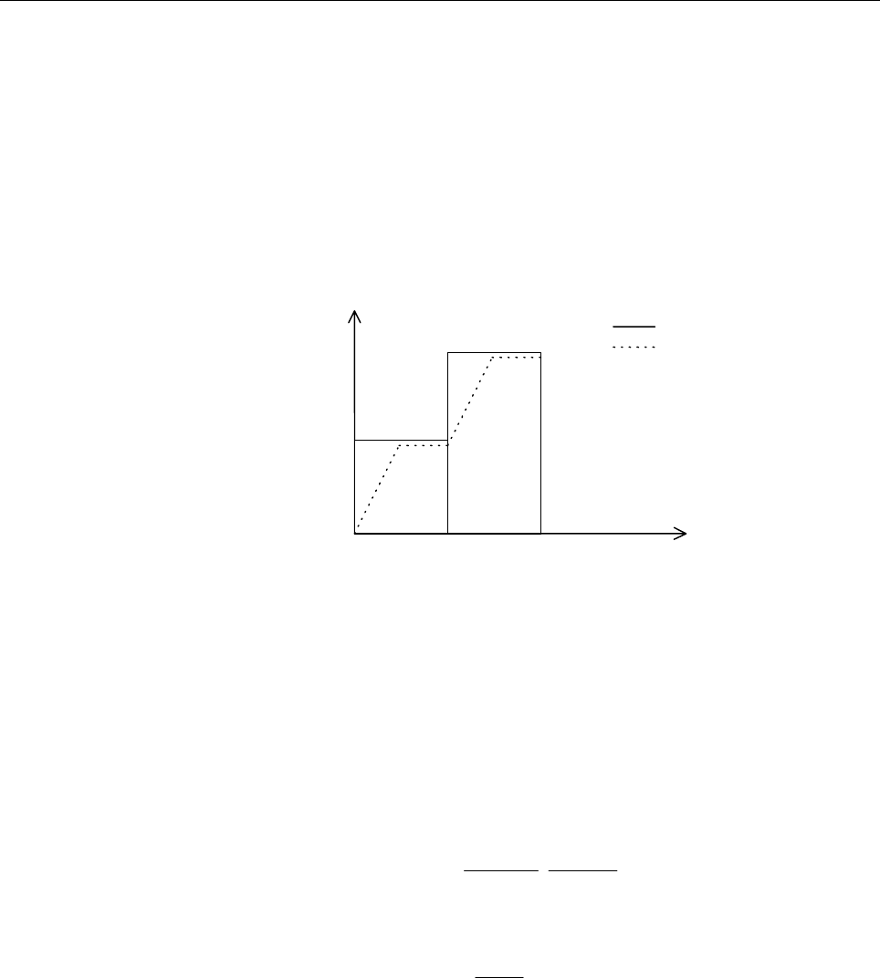
To reduce the speed from speed F3 to speed F2, deceleration must
start at point 1.
To reduce the speed from speed F2 to speed F1, deceleration must
start at point 2.
Because look-ahead of up to 40 blocks can be performed, deceleration
can extend over several blocks.
(Acceleration example)
During execution, acceleration is performed so that the speed
specified for one block is achieved.
Speed
Time
N1 N2
F1
F2
F3
Specified speed
Speed after
acceleration/deceleration
before inter
p
olation
Automatic corner deceleration
Using for reference the axis for which the ratio of the actual speed
difference to the permissible speed difference is the largest of the axes
for which the speed difference on each axis between blocks exceeds
the setting (parameter No. 1783), this function calculates the speed at
a corner as described below, and decelerates the tool to achieve that
speed at the block joint.
The speed changes on the respective axes (Vx, Vy, ...) during
movement at the specified speed F are compared with the settings of
parameter No. 1783 (Vprm-x, Vprm-y, ...). If the speed change on any
axis exceeds the corresponding parameter setting,
−
=
...
y-Vprm
Vy
xVprm
Vx
maxRmax
、
,
the speed (Fc) is determined as given below and deceleration is
performed at the corner.
where
Rmax
1
FFc
×=
For example, assuming that the specified feedrate is 1000 mm/min and
the permissible speed difference (parameter No. 1783) is 500 mm/min,
deceleration is performed as shown in the next figure if the tool
movement direction changes by 90 degrees from X axis to Y axis.
Contents Summary of Series 16i/160i-LB Connection manual (Function)
- Page 1FANUC Series 16*-LB FANUC Series 160*-LB CONNECTION MANUAL B-63663EN/01
- Page 2• No part of this manual may be reproduced in any form. • All specifications and designs are subject to change without notice. The export of this product is subject to the authorization of the government of the country from where the product is exported. In this manual we have tried as much as possi
- Page 3B-63663EN/01 DEFINITION OF WARNING, CAUTION, AND NOTE DEFINITION OF WARNING, CAUTION, AND NOTE This manual includes safety precautions for protecting the user and preventing damage to the machine. Precautions are classified into Warning and Caution according to their bearing on safety. Also, supplem
- Page 4
- Page 5B-64663EN/01 PREFACE PREFACE About this manual "Connection Manual (Hardware) (B-63523EN)" and "Connection Manual (Function) (B-63523EN-1)" for Series 16i/160i-MODEL B and this manual are provided to design a laser processing machine. The "Hardware" and "Function" connection manuals provide general c
- Page 6PREFACE B-64663EN/01 Applicable product This manual explains the following product. In the manual, the following abbreviation may be used. Product name Abbreviations FANUC Series 16i-LB 16i-LB FANUC Series 160i-LB 160i-LB - Representation of bit type and bit-axis type parameters Data No. Data (#0 to
- Page 7B-64663EN/01 PREFACE Related manuals of Series Series 16i/160i-LB The following table lists the manuals related to Series 16i-LB, Series 160i-LB. This manual is indicated by an asterisk (*). Related manuals of Series Series Series 16i/160i-LB Specification Manual name number Series 16i/18i/21i/160i/
- Page 8PREFACE B-64663EN/01 Related manuals of SERVO MOTOR αi/βi series The following table lists the manuals related to SERVO MOTOR αi/βi series. Specification Manual name number FANUC AC SERVO MOTOR αis series FANUC AC SERVO MOTOR αi series B-65262EN DESCRIPTIONS FANUC AC SPINDLE MOTOR αi series B-65272E
- Page 9B-64663EN/01 PREFACE Related manuals of SERVO MOTOR α series The following table lists the manuals related to SERVO MOTOR α series. Specification Manual name number FANUC AC SERVO MOTOR α series DESCRIPTIONS B-65142E FANUC AC SERVO MOTOR α series B-65150E PARAMETER MANUAL FANUC AC SPINDLE MOTOR α se
- Page 10
- Page 11B-63663EN/01 TABLE OF CONTENTS TABLE OF CONTENTS DEFINITION OF WARNING, CAUTION, AND NOTE .................................s-1 PREFACE ....................................................................................................p-1 I. HARDWARE 1 OVERVIEW ......................................
- Page 12TABLE OF CONTENTS B-63663EN/01 2.3.1 Machine Lock.........................................................................................................40 2.3.2 Dry Run ..................................................................................................................40 2.3.3 Single
- Page 13B-63663EN/01 TABLE OF CONTENTS 7 THREE-DIMENSIONAL MACHINING SYSTEM ................................. 106 7.1 ATTITUDE CONTROL............................................................................... 107 7.1.1 Attitude Control A (Zero-offset Head)...............................................
- Page 14
- Page 15I. HARDWAR
- Page 16
- Page 17B-64663EN/01 HARDWARE 1.OVERVIEW 1 OVERVIEW -3-
- Page 181.OVERVIEW HARDWARE B-64663EN/01 1.1 DIFFERENCES BETWEEN Series 16i-LB AND Series 16i Configure the Series 16i-LB system by making connections as described in the "Series 16i-B Connection Manual." For an explanation of the differences between the Series 16i-LB and Series 16i, refer to this manual as
- Page 19B-64663EN/01 HARDWARE 2.CONFIGURATION 2 CONFIGURATION Host computer Heat exchanger Relay connector Manual pulse generator MDI unit I/O device Operator's panel Machine Control unit I/O module etc. operator's panel Connector panel I/O Power 24 VDC module, I/O unit, etc. magnetics power Sensor/actuator
- Page 203.CONTROL UNIT HARDWARE B-64663EN/01 3 CONTROL UNIT -6-
- Page 21B-64663EN/01 HARDWARE 3.CONTROL UNIT 3.1 CONFIGURATION OF THE CONTROL UNIT Serial communication board Loader control board Motherboard Remote buffer Loader control function CPU for controlling CNC /DNC1/DNC2/HDLC - 2/4-axis control - Power supply - 2-axis to 8-axis control - LCD/MDI C language board
- Page 223.CONTROL UNIT HARDWARE B-64663EN/01 3-slot rack Slot 0 1-slot rack Option slot 2 Option slot 1 Mini slot 10 Mini slot 12 Mini slot 10 Mini slot 9 Mini slot 11 Mini slot 9 Option (mini slots) Option Basic system (slot 1) HSSB interface board RISC board Main board High-speed serial bus interface (16i
- Page 23B-64663EN/01 HARDWARE 4.TOTAL CONNECTION DIAGRAM 4 TOTAL CONNECTION DIAGRAM -9-
- Page 244.TOTAL CONNECTION DIAGRAM HARDWARE B-64663EN/01 4.1 FOR C SERIES AND Y SERIES OSCILLATORS LCD-mounted type control unit (except 160i with PC) Motherboard LCD 24 VDC power Soft key cable RS-232C I/O device RS-232C I/O device Touch panel Assist gas pressure analog output High-speed skip input Distrib
- Page 25B-64663EN/01 HARDWARE 4.TOTAL CONNECTION DIAGRAM LCD-mounted type control unit (when the option function is provided) Serial communication Optional slot board Remote buffer board DNC1 board DNC2 board RS-232C I/O device (when the remote buffer board or DNC2 board is used) RS-422 I/O device (when the
- Page 264.TOTAL CONNECTION DIAGRAM HARDWARE B-64663EN/01 LCD-mounted type control unit (when the option function is provided) Circuit breaker Optional slot Loader control board AC rector Circuit breaker Loader axis 1 servo motor Loader axis 2 servo motor Loader axis 3 servo motor Loader axis 4 servo motor (
- Page 27B-64663EN/01 HARDWARE 4.TOTAL CONNECTION DIAGRAM Stand-alone type control unit Main board Slot 0 24 VDC power The SOFT KEY cable is To I/O device etc. connected to the LCD control printed circuit board. Optical fiber cable Memory card (Touch panel) RS-232C I/O device RS-232C I/O device Assist gas pr
- Page 284.TOTAL CONNECTION DIAGRAM HARDWARE B-64663EN/01 Stand-alone type control unit Slot 2 Data Server board Hard disk unit Mini slot Analog option board Tracing sensor Assist gas pressure analog output (Note) This servo interface cannot be used by the MT system. Only the servo interface of the main boar
- Page 29B-64663EN/01 HARDWARE 5.POWER SUPPLY 5 POWER SUPPLY - 15 -
- Page 305.POWER SUPPLY HARDWARE B-64663EN/01 5.1 CONTROL UNIT POWER SUPPLY Supply power (24 VDC) from an external source to the control unit of the Series 16i-LB/160i-LB system. Install an external power-on/off switch for the control unit, as shown in the figure below. When the Series 160i-LB system with PC
- Page 31B-64663EN/01 HARDWARE 5.POWER SUPPLY Sample on/off circuit The figure below shows a sample on/off circuit. Select the circuit devices according to the actual power rating. Connect the OFF and COM lines to the OF11 and OF12 contacts of the laser oscillator, respectively, so that an interlock can be a
- Page 326.I/O LIMITATION BASED ON LASER OSCILLATOR CONNECTIONHARDWARE B-64663EN/01 6 I/O LIMITATION BASED ON LASER OSCILLATOR CONNECTION In the FS16i-LB system, the laser oscillator is connected in serial via the I/O unit. For a laser oscillator interface, three groups with 256 DI and 256 DO points are rese
- Page 33B-64663EN/01 HARDWARE 7.LASER OSCILLATOR 7 LASER OSCILLATOR - 19 -
- Page 347.LASER OSCILLATOR HARDWARE B-64663EN/01 7.1 CONNECTION OF THE LASER OSCILLATOR (1) When the version of the laser IF-PCB is earlier than A16B-2100-0141/07D (2) When the version of the laser IF-PCB is earlier than A16B-2100-0141/07D - 20 -
- Page 35B-64663EN/01 HARDWARE 7.LASER OSCILLATOR 7.1.1 Connection of the CP1A CP1A is placed on the adaptor when the version of the laser IF-PCB (A16B-2100-0141) is earlier than 07D. CP1A is placed on the IF-PCB when the version of the laser IF-PCB is 07D or later. - 21 -
- Page 367.LASER OSCILLATOR HARDWARE B-64663EN/01 7.2 LASER OSCILLATOR CONNECTION USING AN OPTICAL FIBER CABLE When one of the following conditions is satisfied, an optical fiber cable must be used to connect the laser oscillator to the I/O link: (1) The length of the required cable is at least 10 m. (2) A 5
- Page 37B-64663EN/01 HARDWARE 7.LASER OSCILLATOR CAUTION 1 To daisy-chain I/O units to a single I/O link, both optical fiber cables and electrical cables can be used. 2 When an optical fiber cable is used, an optical I/O link adaptor must also be used. 3 Two types of optical I/O link adaptors are supported:
- Page 387.LASER OSCILLATOR HARDWARE B-64663EN/01 7.3 ASSIST GAS PRESSURE ANALOG OUTPUT Assist gas pressure analog output signals are output from either the analog spindle interface on the main board or the analog output interface on the analog option board. Which interface to use can be specified with the a
- Page 39B-64663EN/01 HARDWARE 7.LASER OSCILLATOR To output signals from the analog option board CAUTION 1 AOUT, 0V: Common lines are used for the AOUT, 0V, and assist gas pressure analog output signals. 2 The signals in parentheses cannot be used. 3 For details of the output voltage, see Section 4.1 "ASSIST
- Page 407.LASER OSCILLATOR HARDWARE B-64663EN/01 7.4 CONNECTION OF THE TRACING SENSOR CAUTION 1 AIN0, 0V: Common lines are used for the AIN0, 0V, and analog input signals. 2 The signals in parentheses cannot be used. 2 For details of the input voltage, see the section on tracing control in the function desc
- Page 41II. LASER FUNCTIO
- Page 42
- Page 43B-64663EN/01 LASER FUNCTION 1.FUNCTIONS 1 Overview FUNCTIONS For information about connections other than the laser functions, refer to the "16i/160i-MODEL B Connection Manual (Function) (B-63523EN-1)”. Most of the functions described in manual (B-63523EN-1) can be used with the 16i-LB. Note, howeve
- Page 441.FUNCTIONS LASER FUNCTION B-64663EN/01 Item Specifications 16i-LB 160i-LB Least input increment 0.001mm, 0.001deg, 0.0001inch ○ ○ Flexible feed gear Optional DMR ○ ○ Dual position feedback ☆ ☆ Fine acceleration/deceleration ○ ○ HRV control ○ ○ High-speed HRV control ○ ○ Inch/metric conversion ☆ ☆ A
- Page 45B-64663EN/01 LASER FUNCTION 1.FUNCTIONS Item Specifications 16i-LB 160i-LB 1 unit ☆ ☆ Manual handle feed 2 or 3 units ☆ ☆ Manual handle feed rate ×1, ×10, ×m, ×n * * Manual handle interruption ☆ ☆ Incremental feed ×1, ×10, ×100, ×1000 ○ ○ Jog and handle simultaneous mode ○ ○ Interpolation Item Speci
- Page 461.FUNCTIONS LASER FUNCTION B-64663EN/01 Item Specifications 16i-LB 160i-LB 2nd feedrate override 0% to 254% ☆ ☆ One-digit F code feed ☆ ☆ Jog override 0% to 655.34% ○ ○ Override cancel ○ ○ External deceleration ☆ ☆ Feed stop ☆ ☆ Advanced preview control ☆ ☆ AI contour control ☆ ☆ Bell–shaped acceler
- Page 47B-64663EN/01 LASER FUNCTION 1.FUNCTIONS Item Specifications 16i-LB 160i-LB Scaling ☆ ☆ Coordinate system rotation ☆ ☆ Programmable mirror image ☆ ☆ Figure copy ☆ ☆ Retrace ☆ ☆ Tape format for FANUC Series 15 ☆ ☆ Macro executor Max. 6MB ☆ ☆ C language executor Max. 6MB ☆ ☆ Auxiliary function Item Spe
- Page 481.FUNCTIONS LASER FUNCTION B-64663EN/01 Item Specifications 16i-LB 160i-LB Background editing ☆ ☆ Extended part program editing ☆ ☆ Playback ☆ ☆ Machining time stamp ☆ ☆ Setting and display Item Specifications 16i-LB 160i-LB Status display ○ ○ Clock function ○ ○ Current position display ○ ○ Program
- Page 49B-64663EN/01 LASER FUNCTION 1.FUNCTIONS Data input/output Item Specifications 16i-LB 160i-LB Reader/puncher (channel 1) interface ☆ ☆ Reader/puncher interface Reader/puncher (channel 2) interface ☆ ☆ Input/output simultaneous operation ☆ ☆ Remote buffer ☆ ☆ High-speed remote buffer A ☆ ☆ Data server
- Page 501.FUNCTIONS LASER FUNCTION B-64663EN/01 Item Specifications 16i-LB 160i-LB Purge completed, gas pressure under Laser status output signal control, base discharging, discharge start ○ ○ ready, etc. Tracing control G13, G14 ☆ ☆ Tracing interlock function * * Cutting condition setting function ☆ ☆ Edge
- Page 51B-64663EN/01 LASER FUNCTION 1.FUNCTIONS Item Specifications 16i-LB 160i-LB Touch panel Only for 10.4″ LCD or 12.1″ LCD ● ● Basic instruction : 0.033 µsec/step ○ ○ PMC-SB7 Max. step number ladder: 64,000 PMC Step sequence function ☆ ☆ system Max. 2MB ☆ ☆ C language Nonvolatile memory expansion ☆ ☆ I/
- Page 522.FUNCTIONS DIFFERING FROM THE M SERIES SPECIFICATIONS LASER FUNCTION B-64663EN/01 2 FUNCTIONS DIFFERING FROM THE M SERIES SPECIFICATIONS Overview The specifications of some functions of the 16i-LB differ from those of the functions explained in "16i-MODEL B Connection Manual: (Function) (B-63523EN-
- Page 53B-64663EN/01 LASER FUNCTION 2.FUNCTIONS DIFFERING FROM THE M SERIES SPECIFICATIONS 2.1 EMERGENCY STOP Difference When the emergency stop signal (*ESP) is set to 0 while the oscillator is in the oscillation state (LSTR=1), the beam is turned off, and none of the assist gas select signals (AG1 to AG3)
- Page 542.FUNCTIONS DIFFERING FROM THE M SERIES SPECIFICATIONS LASER FUNCTION B-64663EN/01 2.3 TEST OPERATION 2.3.1 Machine Lock Difference When beam output is programmed, all commands relating to beam output are ignored. Instead, only machine move commands are executed (the beam remains off) and the curren
- Page 55B-64663EN/01 LASER FUNCTION 2.FUNCTIONS DIFFERING FROM THE M SERIES SPECIFICATIONS 2.3.3 Single Block Difference When a beam output command block is executed and terminated, feed stops, the beam is turned off, the shutter is closed, and none of the assist gas select signals (AG1 to AG3) is selected.
- Page 562.FUNCTIONS DIFFERING FROM THE M SERIES SPECIFICATIONS LASER FUNCTION B-64663EN/01 2.4 PROGRAM RESTART (LASER SPECIFICATIONS) Overview If machining is stopped during automatic operation, machining can be resumed from a specified block. Signal - Program restart signal REST2
- Page 57B-64663EN/01 LASER FUNCTION 2.FUNCTIONS DIFFERING FROM THE M SERIES SPECIFICATIONS - Proximity point search in progress signal LNSR
- Page 582.FUNCTIONS DIFFERING FROM THE M SERIES SPECIFICATIONS LASER FUNCTION B-64663EN/01 NMC With the proximity point search of the offset type and the program restart function, positioning to the restart point is: 0: Executed for all axes at the same time. 1: Executed for the fourth and fifth axes first,
- Page 59B-64663EN/01 LASER FUNCTION 3.LASER SEQUENCE CONTROL 3 LASER SEQUENCE CONTROL - 45 -
- Page 603.LASER SEQUENCE CONTROL LASER FUNCTION B-64663EN/01 3.1 SEQUENCE CONTROL OF THE C SERIES AND Y SERIES LASER OSCILLATORS Overview The C series (CO2 Laser) and Y series (continuously output type YAG) laser oscillators are activated and stopped according to the following sequence chart. - 46 -
- Page 61B-64663EN/01 LASER FUNCTION 3.LASER SEQUENCE CONTROL Oscillator start sequence The sequence of operations from when the power to the oscillator is turned on to when the oscillator starts oscillation and the response of the CNC to these actions are described below. (1) When the power to the oscillato
- Page 623.LASER SEQUENCE CONTROL LASER FUNCTION B-64663EN/01 The timing chart for operations after the power is turned on is shown below. In the figure, a solid line indicates the time during which a signal is on or 1. Oscillator stop sequence To turn off the power to the laser oscillator, follow the proced
- Page 63B-64663EN/01 LASER FUNCTION 3.LASER SEQUENCE CONTROL The timing chart for operations before the power is turned off is shown below. Signal - Purge completion signal PURGE
- Page 643.LASER SEQUENCE CONTROL LASER FUNCTION B-64663EN/01 Stopping the oscillator When the oscillator start signal (RUN) is set to 0 during operation, if discharge is being performed, the CNC stops discharge. If discharge is not being performed, the CNC immediately closes the laser gas supply valve, and
- Page 65B-64663EN/01 LASER FUNCTION 3.LASER SEQUENCE CONTROL - Chiller start request signal CLON
- Page 663.LASER SEQUENCE CONTROL LASER FUNCTION B-64663EN/01 The signal becomes 0 under the following conditions: - When the discharge start signal (HVON) is set to 1 while the discharge start ready signal (LRDY) is set to 1 - When the oscillator start signal (RUN) is set to 0 while the discharge start read
- Page 67B-64663EN/01 LASER FUNCTION 3.LASER SEQUENCE CONTROL Signal address #7 #6 #5 #4 #3 #2 #1 #0 G221 CLRDY G222 HVON RUN F221 LSTR RFHV CLON WAIT PURGE LRDY Parameter #7 #6 #5 #4 #3 #2 #1 #0 15004 CWY [Data type] Bit CWY Specifies the type of laser oscillator to be connected. 0: CO2 laser 1: CW-YAG lase
- Page 684.ASSIST GAS LASER FUNCTION B-64663EN/01 4 ASSIST GAS - 54 -
- Page 69B-64663EN/01 LASER FUNCTION 4.ASSIST GAS 4.1 ASSIST GAS CONTROL Overview When bit 6 (LHC) of parameter No.15001 is set to 0, assist gas control described below can be performed. Assist gas control can be specified in either of the following two ways: <1> Directly specifying gas pressure control (whe
- Page 704.ASSIST GAS LASER FUNCTION B-64663EN/01 (b) Specifying assist gas control using the machining condition setting function G32L - ; 0: Shutter closed, assist gas stopped 1: Shutter opened, assist gas flow started according to the machining data 2: Shutter opened, assist gas flow started according to
- Page 71B-64663EN/01 LASER FUNCTION 4.ASSIST GAS Specifying a flow pattern When bit 0 (AGC) of parameter No.15004 is set to 0, a flow pattern can be specified. G32, for which a non-zero value has been specified for address P, opens the shutter and outputs an assist gas select signal (AG1, AG2, or AG3) and a
- Page 724.ASSIST GAS LASER FUNCTION B-64663EN/01 Switching between direct gas pressure control specification and flow pattern specification The G32 command does not necessarily require that T, R, and Q be specified. If none is specified, however, the system cannot decide whether gas pressure control is spec
- Page 73B-64663EN/01 LASER FUNCTION 4.ASSIST GAS Signal - Assist gas select signals AG1,AG2,AG3
- Page 744.ASSIST GAS LASER FUNCTION B-64663EN/01 - Assist gas start signal AGST
- Page 75B-64663EN/01 LASER FUNCTION 4.ASSIST GAS When a flow pattern is specified If the gas flow pattern data is set in the gas flow field of the laser setting screen, assist gas control is performed as described below: G32 P_ Q_; (non-zero values for P and Q) starts assist gas control, causing the specifi
- Page 764.ASSIST GAS LASER FUNCTION B-64663EN/01 LHC Oscillator control (shutter open/close, beam on/off, assist gas control) is: 0: Not performed by external signals. Assist gas control is specified by G32. (standard setting) 1: Performed by external signals. The PMC performs assist gas control. #7 #6 #5 #
- Page 77B-64663EN/01 LASER FUNCTION 4.ASSIST GAS 4.2 ASSIST GAS PRESSURE ANALOG OUTPUT Overview When assist gas control is specified, the CNC outputs the specified assist gas pressure as an analog voltage signal. As the destination of the signal, either the analog spindle interface on the main board or the
- Page 784.ASSIST GAS LASER FUNCTION B-64663EN/01 Parameter #7 #6 #5 #4 #3 #2 #1 #0 15011 AOC [Data type] Bit AOC The analog output of the assist gas pressure command is output from: 0: The connector (JA40) on the main board. 1: The connector (JA6) on the analog option board. 15132 Maximum assist gas pressur
- Page 79B-64663EN/01 LASER FUNCTION 4.ASSIST GAS 4.3 ASSIST GAS PRESSURE OVERRIDE Overview It is possible to override the assist gas pressure analog output with 0 to 200% of it in units of 1%. Signal - Assist gas pressure override signals *AOV0 to *AOV7
- Page 805.LASER OUTPUT CONTROL LASER FUNCTION B-64663EN/01 5 LASER OUTPUT CONTROL - 66 -
- Page 81B-64663EN/01 LASER FUNCTION 5.LASER OUTPUT CONTROL 5.1 SHUTTER OPENING/CLOSING CONTROL Overview The output section of the oscillator contains a shutter that mechanically shuts off the laser beam output. This shutter is provided as a safety device. The laser can be output only after the shutter has b
- Page 825.LASER OUTPUT CONTROL LASER FUNCTION B-64663EN/01 Signal - Shutter lock signal *SHTLC
- Page 83B-64663EN/01 LASER FUNCTION 5.LASER OUTPUT CONTROL Parameter #7 #6 #5 #4 #3 #2 #1 #0 15001 LHC [Data type] Bit LHC Oscillator control (shutter open/close, beam on/off, assist gas control) is: 0: Not performed by external signals. The shutter is opened and closed by G32. (standard setting) 1: Perform
- Page 845.LASER OUTPUT CONTROL LASER FUNCTION B-64663EN/01 5.2 BEAM ON/OFF CONTROL Overview When the shutter is open, executing a beam output command causes the oscillator to radiate the laser beam to the outside. The beam output command can be issued by either of the following methods, according to the bit
- Page 85B-64663EN/01 LASER FUNCTION 5.LASER OUTPUT CONTROL To execute a machining program without outputting the laser beam, set both the beam lock signal (*BEMLC) and shutter lock signal (*SHTLC) to 0. This setting can also be used to operate the machine while the oscillator is not connected or not adjuste
- Page 865.LASER OUTPUT CONTROL LASER FUNCTION B-64663EN/01 - Mode output signal CW
- Page 87B-64663EN/01 LASER FUNCTION 5.LASER OUTPUT CONTROL No. Message Contents The actual output is lower than the specified LASER POWER 4076 average power by a predetermined value or DOWN greater. Assist gas signals were not output. ASSIST GAS NO 4089 Assist gas signals AG1 to AG3 (F0222#0 to SELECT F0222
- Page 885.LASER OUTPUT CONTROL LASER FUNCTION B-64663EN/01 5.3 OUTPUT OVERRIDE 5.3.1 Power Override Signal Overview When the C-series or Y-series oscillator is being used, the currently set output power can be overridden. The override value can be specified within a range of 0% to 200%, in units of 1%. Sign
- Page 89B-64663EN/01 LASER FUNCTION 5.LASER OUTPUT CONTROL 5.3.2 Frequency Override Signal Overview The currently set pulse frequency of the laser oscillator can be overridden. Signal - Frequency override signals *FOV0 to *FOV7
- Page 905.LASER OUTPUT CONTROL LASER FUNCTION B-64663EN/01 5.3.3 Duty Override Overview When the C-series or Y-series oscillator is being used, the currently set laser output pulse duty can be overridden. Signal - Duty override signals *DU1 to *DU16
- Page 91B-64663EN/01 LASER FUNCTION 5.LASER OUTPUT CONTROL 5.4 CHANGING THE PIERCING TIME Overview When the C-series or Y-series oscillator is used, external signals can be used to change the piercing time specified by G24. When the CNC executes G24, it presets the timer to the specified piercing time. Whil
- Page 925.LASER OUTPUT CONTROL LASER FUNCTION B-64663EN/01 Signal - Piercing time reduction signal PTS
- Page 93B-64663EN/01 LASER FUNCTION 5.LASER OUTPUT CONTROL Signal address #7 #6 #5 #4 #3 #2 #1 #0 G221 PTE PTS Parameter #7 #6 #5 #4 #3 #2 #1 #0 15003 HPT [Data type] Bit HPT When the function for changing the piercing time is executed, the newly specified piercing time: 0: Replaces the current data. 1: Doe
- Page 945.LASER OUTPUT CONTROL LASER FUNCTION B-64663EN/01 5.5 GUIDE LIGHT ON SIGNAL Overview If the laser oscillator contains an optional guide light unit (semiconductor laser), an external signal can be used to turn the guide light laser unit on or off. CAUTION The external guide light on signal (SCLON) m
- Page 95B-64663EN/01 LASER FUNCTION 5.LASER OUTPUT CONTROL 5.6 STATE OUTPUT SIGNAL 5.6.1 Piercing Signal Overview A signal is output to indicate that piercing specified by G24 is in progress. Signal - Piercing signal PIRC
- Page 965.LASER OUTPUT CONTROL LASER FUNCTION B-64663EN/01 5.6.2 Laser Processing Signal Overview The laser processing signal is output for the time between assist gas output being started and tracing control being cancelled. Signal - Laser processing signal LPRC
- Page 97B-64663EN/01 LASER FUNCTION 5.LASER OUTPUT CONTROL 5.6.3 Output Drop Alarm Signal Overview As the mirror of the resonator becomes dirty, laser output will drop. When the laser oscillator is activated, the power compensation coefficient is automatically calculated. By specifying this coefficient for
- Page 985.LASER OUTPUT CONTROL LASER FUNCTION B-64663EN/01 5.6.4 Laser Alarm Signal Overview When a laser oscillator error is detected, a laser alarm occurs. Signal - Laser alarm signal LARM
- Page 99B-64663EN/01 LASER FUNCTION 5.LASER OUTPUT CONTROL 5.6.5 Laser Oscillator Not Connected Signal Overview This signal is output if no laser oscillator is connected. Signal - Laser oscillator not connected signal LONC
- Page 1006.TRACING CONTROL LASER FUNCTION B-64663EN/01 6 TRACING CONTROL - 86 -
- Page 101B-64663EN/01 LASER FUNCTION 6.TRACING CONTROL 6.1 TRACING CONTROL 6.1.1 Tracing Function Overview When a sensor for detecting the distance to a workpiece is mounted on the Z-axis, and a signal from this sensor is sent to the CNC, the CNC outputs a Z-axis (W-axis) move command to establish a specifie
- Page 1026.TRACING CONTROL LASER FUNCTION B-64663EN/01 Polarity of the sense signal The sensor should be designed to send a 0-V sense signal when the nozzle is at the reference distance (L0) position and then output voltage in proportion to any shift from the reference position. Positive voltage should be ou
- Page 103B-64663EN/01 LASER FUNCTION 6.TRACING CONTROL Sensor performance Tracking accuracy depends on the linearity of the sensor. So, use only a sensor having extremely high linearity. The frequency characteristics of the amplifier and sensor greatly affect the response of the tracing control system. So, u
- Page 1046.TRACING CONTROL LASER FUNCTION B-64663EN/01 This signal is set to 0 in the following case: - When a tracing stop condition is accepted When an M code is used to start and stop tracing, the tracing motion signal (TRCL) set to 1 must be confirmed after the tracing start signal (TCST) is set to 1. Th
- Page 105B-64663EN/01 LASER FUNCTION 6.TRACING CONTROL 6.1.2 Tracing Control Adjustment Overview After connecting the signal from the sensor to the CNC, make the adjustments described below. Sensor adjustment Position the sensor so that the distance between the sensor and workpiece is equal to the sensor str
- Page 1066.TRACING CONTROL LASER FUNCTION B-64663EN/01 Zero point adjustment Set a zero point with the trace setting screen. Repeat the following operation a few times to check that there is no significant setting variation (within about ±320). Select the trace setting screen. Move the nozzle towards the wor
- Page 107B-64663EN/01 LASER FUNCTION 6.TRACING CONTROL The higher the tracing gain, the better the tracking capability. However, too great a gain results in unstable operation, causing oscillation within the system. So, a gain that ensures stable operation must be determined and set. Gain setting procedure <
- Page 1086.TRACING CONTROL LASER FUNCTION B-64663EN/01 15503 Filter time constant [Data type] Word [Unit of data] msec [Valid data range] 0 to 32767 (except 1) [Standard setting value] 0 If tracing becomes unstable as a result of a disturbance such as mechanical vibration superimposed on the sense signal, se
- Page 109B-64663EN/01 LASER FUNCTION 6.TRACING CONTROL 15510 Integral time constant : standard setting value=300 Integral compensation zero width : 15511 standard setting value=30000 (Not required) 15512 Integral clamp value : standard setting value=0 (Not required) 15520 Phase compensation time constant : s
- Page 1106.TRACING CONTROL LASER FUNCTION B-64663EN/01 How to specify the standard shift The standard shift can be specify as follows: <1> In program G13P_ ; Specify the value in address P. <2> By means of setting data Changes can be made in the trace setting screen. <3> By means of the machining condition s
- Page 111B-64663EN/01 LASER FUNCTION 6.TRACING CONTROL 6.1.4 Approach Approach If tracing is started when the nozzle is raised from the workpiece, the nozzle will start moving towards the workpiece. This operation is referred to as approach. Approach speed The speed of the approach motion is calculated using
- Page 1126.TRACING CONTROL LASER FUNCTION B-64663EN/01 Parameter 15550 Approach-completion-sensing band width (APRCH) [Data type] Word [Unit of data] 0.001mm [Valid data range] 0 to 32767 [Standard setting value] 50 Set the amount of shift used to assume approach completion. Approach completion is assumed wh
- Page 113B-64663EN/01 LASER FUNCTION 6.TRACING CONTROL 6.1.5 Tracing Alarm Overview Two check functions are provided for tracing. Over-shift alarm If, during approach, the nozzle comes too close to the workpiece, the nozzle is stopped by means of the over-shift alarm, and the alarm signal (TRALM) is sent to
- Page 1146.TRACING CONTROL LASER FUNCTION B-64663EN/01 - Trace check mode signal TRCKM
- Page 115B-64663EN/01 LASER FUNCTION 6.TRACING CONTROL 15537 Tracing range-over alarm (EOVRS) [Data type] Word [Unit of data] 0.001mm [Valid data range] 0 to 32767 [Standard setting value] 1000 When the absolute value of a tracing shift exceeds the value set in this parameter, an alarm, or a signal indicatin
- Page 1166.TRACING CONTROL LASER FUNCTION B-64663EN/01 6.1.6 Tracing Gain Override Overview Tracing gain can be overridden in steps of 12.5%. Signal - Tracing gain override GAPG0 to GAPG2
- Page 117B-64663EN/01 LASER FUNCTION 6.TRACING CONTROL 6.2 TRACING INTERLOCK FUNCTION Overview Once this external signal has been turned on during tracing control, interlock is applied to tracing control while the signal is on, thus stopping tracing control. While tracing control is enabled, the nozzle may b
- Page 1186.TRACING CONTROL LASER FUNCTION B-64663EN/01 Reset processing When interlock is applied to tracing control with the *TRIL signal set to 0, a reset operation cancels tracing control mode as well as interlock. Signal - Tracing interlock signal *TRIL
- Page 119B-64663EN/01 LASER FUNCTION 6.TRACING CONTROL 6.3 TRACING AXIS MACHINE LOCK Overview In tracing mode, the tracing axis can be stopped by changing its speed to 0. This does not cause the system to leave tracing mode. The axis can therefore be stopped before tracing mode is canceled. Signal - Tracing
- Page 1207.THREE-DIMENSIONAL MACHINING SYSTEM LASER FUNCTION B-64663EN/01 7 THREE-DIMENSIONAL MACHINING SYSTEM - 106 -
- Page 121B-64663EN/01 LASER FUNCTION 7.THREE-DIMENSIONAL MACHINING SYSTEM 7.1 ATTITUDE CONTROL Overview Specifying five or more control axes as well as attitude control allows attitude control of a nozzle with the fourth and fifth axes as rotation axes, enabling a three-dimensional machine to be configured.
- Page 1227.THREE-DIMENSIONAL MACHINING SYSTEM LASER FUNCTION B-64663EN/01 7.1.1 Attitude Control A (Zero-offset Head) Overview The nozzle-head position fixing (zero-offset) mechanism consists of the α (4th) axis, that rotates around the Z-axis, and the β (5th) rotation axis, that is associated with the α axi
- Page 123B-64663EN/01 LASER FUNCTION 7.THREE-DIMENSIONAL MACHINING SYSTEM Reference positions The reference positions of the α and β axes are indicated by their zero-degree positions and rotation directions shown in the above figure. Reference position of the α axis When the α axis is viewed from the +Z dire
- Page 1247.THREE-DIMENSIONAL MACHINING SYSTEM LASER FUNCTION B-64663EN/01 Namely, the α axis is rotated by the command specifying the α axis at the same time the β axis is rotated. The interaction control function automatically issues the same command as the command specifying the α axis for the β axis to ca
- Page 125B-64663EN/01 LASER FUNCTION 7.THREE-DIMENSIONAL MACHINING SYSTEM #7 #6 #5 #4 #3 #2 #1 #0 15601 PA5 PA4 [Data type] Bit PA4 The α axis rotates: 0: In the same direction as that defined for the reference position. 1: In the opposite direction to that defined for the reference position. PA5 The β axis
- Page 1267.THREE-DIMENSIONAL MACHINING SYSTEM LASER FUNCTION B-64663EN/01 7.1.2 Attitude Control B (Offset Nozzle) Overview The offset mechanism consists of the α (4th) axis that rotates on the Z axis and the β (5th) rotation axis associated with the α axis. In this structure, the nozzle head is positioned a
- Page 127B-64663EN/01 LASER FUNCTION 7.THREE-DIMENSIONAL MACHINING SYSTEM Reference attitude of the β axis When the α axis is set to 0° and the β axis is viewed from the +X direction, the position where the nozzle faces in the -Z direction is 0°. When +90° rotation from that position is commanded, the β axis
- Page 1287.THREE-DIMENSIONAL MACHINING SYSTEM LASER FUNCTION B-64663EN/01 Nozzle head fixing mode When the command specifying the α or β axis is issued, the specified axis is rotated at the same time linear axes X, Y, and Z are moved. This allows the specified axis to rotate around the nozzle head position.
- Page 129B-64663EN/01 LASER FUNCTION 7.THREE-DIMENSIONAL MACHINING SYSTEM In the following description, the axis names A and B represent the fourth and fifth axes, respectively. The maximum feedrate on the X axis that has been compensated for by attitude control B can be estimated with the following formula:
- Page 1307.THREE-DIMENSIONAL MACHINING SYSTEM LASER FUNCTION B-64663EN/01 Sample Assume the following: Length of the first arm: 130mm Length of the second arm: 145mm Rapid traverse rates on the respective axes: 24000 for X, 24000 for Y, 20000 for Z, 4000 for A, and 8000 for B Upper speed limits during machin
- Page 131B-64663EN/01 LASER FUNCTION 7.THREE-DIMENSIONAL MACHINING SYSTEM Automatic feedrate override function If the speed specified for the motor for each axis exceeds the speed specified in the corresponding parameter, this function immediately and automatically overrides that speed so that it does not ex
- Page 1327.THREE-DIMENSIONAL MACHINING SYSTEM LASER FUNCTION B-64663EN/01 Interaction control For interaction control of the offset nozzle, the interaction ratio can be set using parameters even when compensation of the β axis does not apply to the command specifying the α axis. Assume that the number of gea
- Page 133B-64663EN/01 LASER FUNCTION 7.THREE-DIMENSIONAL MACHINING SYSTEM Cautions Consider the length of the arm when specifying overtravel because overtravel is monitored with the machine coordinates. In the nozzle head fixing mode, the distances of movement along the X, Y, and Z axes caused by the rotatio
- Page 1347.THREE-DIMENSIONAL MACHINING SYSTEM LASER FUNCTION B-64663EN/01 Signal - Attitude control B speed clamp select signal OTPMX2
- Page 135B-64663EN/01 LASER FUNCTION 7.THREE-DIMENSIONAL MACHINING SYSTEM #7 #6 #5 #4 #3 #2 #1 #0 15600 NFX RNC MIA [Data type] Bit MIA When attitude control B is applied in G53 mode, the nozzle is operated in: 0: Nozzle head fixing mode 1: Independent axis mode (Proximity point search and program restart ar
- Page 1367.THREE-DIMENSIONAL MACHINING SYSTEM LASER FUNCTION B-64663EN/01 FMX If an offset-type nozzle is used, the cutting speed is: 0: Not clamped. 1: Clamped in consideration of the maximum speed after attitude control. 15610 Mechanical zero-degree position offset of the α axis 15611 Mechanical zero-degre
- Page 137B-64663EN/01 LASER FUNCTION 7.THREE-DIMENSIONAL MACHINING SYSTEM 15618 Number of interaction gear teeth of the β axis (TGMLS) [Data type] Byte [Unit of data] [Valid data range] 0 to 127 β axis interaction compensation is calculated using the number of α axis interaction gear teeth, TGMLM of paramete
- Page 1387.THREE-DIMENSIONAL MACHINING SYSTEM LASER FUNCTION B-64663EN/01 7.2 TEACHING BOX INTERFACE Overview If a teaching box interface option is specified, the JD36A or JD36B connector of the motherboard can be used as a teaching box interface. The parameter No.15640 specifies which connector to be used.
- Page 139B-64663EN/01 LASER FUNCTION 7.THREE-DIMENSIONAL MACHINING SYSTEM Setting bit 0 (TBE) of parameter No. 15641 to "1" can switch the communication exclusive right according to the teaching box exclusive right signal (TBES). Resetting the TBES signal to "0" relinquishes the exclusive right to communicat
- Page 1407.THREE-DIMENSIONAL MACHINING SYSTEM LASER FUNCTION B-64663EN/01 - Conversation mode One conversation session consists of two communication phases. The conversation begins when the teaching box requests it, and the CNC responds to the request. (a) When the teaching box sends data to the CNC Header p
- Page 141B-64663EN/01 LASER FUNCTION 7.THREE-DIMENSIONAL MACHINING SYSTEM Notes 1 A command with header H, I, J, K, L, or M is acceptable only during the jog or handle mode. 2 A commands with headers N, T, and U are acceptable only during the MDI mode. Data (c) Data The data must be represented in ASCII code
- Page 1427.THREE-DIMENSIONAL MACHINING SYSTEM LASER FUNCTION B-64663EN/01 Upper byte Lower byte Meaning An end of record code (%) was sent during writing to a specified block. 0 8 Make sure so that "%" is not sent. The number of registered records exceeds 125 (basic), or 200, 400, or 0 9 1000 (option). An at
- Page 143B-64663EN/01 LASER FUNCTION 7.THREE-DIMENSIONAL MACHINING SYSTEM Block number A block number is determined by counting the number of semicolons (EOBs), starting from the beginning of the program. For a program having only an O-number, block number 1 is assumed. O0100; Block number 1 N0001 ; block nu
- Page 1447.THREE-DIMENSIONAL MACHINING SYSTEM LASER FUNCTION B-64663EN/01 When the CNC receives this message, it responds with the completion code: DC2 B 0 0 DC4 12 42 30 30 14 (c) DO (PMC ⇒ TB signal) transmission The TB can read data from the internal relay area. (For area setting, see the Parameter sectio
- Page 145B-64663EN/01 LASER FUNCTION 7.THREE-DIMENSIONAL MACHINING SYSTEM (d) Machine position data request (Workpiece coordinate position) The workpiece coordinate position along the axis specified by the CNC can be read by specifying the name of that axis. TB⇒CNC DC2 D DC4 Axis name 0: X-axis 5: 6th axis 1
- Page 1467.THREE-DIMENSIONAL MACHINING SYSTEM LASER FUNCTION B-64663EN/01 CNC⇒TB Completion DC2 E code DC4 1st byte 2nd byte [Example] Assume that the contouring output power is 1000 W. This example illustrates how the CNC requests and receives data from the TB. Note that 1000 is 03E8H in hexadecimal. Assume
- Page 147B-64663EN/01 LASER FUNCTION 7.THREE-DIMENSIONAL MACHINING SYSTEM CAUTION 1 The program number and block number that can be read with header G are those related to an executed program. Header G cannot be used to read the block number of a program currently under teaching editing. To read it, use a se
- Page 1487.THREE-DIMENSIONAL MACHINING SYSTEM LASER FUNCTION B-64663EN/01 (i) Program number deletion The program with a specified program number is deleted. TB⇒CNC DC2 I DC4 Program number 1st byte 2nd byte CNC⇒TB DC2 I Completion code DC4 (j) Specified-block read By specifying a program number and block nu
- Page 149B-64663EN/01 LASER FUNCTION 7.THREE-DIMENSIONAL MACHINING SYSTEM (K) Specified-block write By specifying a program number, block number, block length, and NC data, the NC data can be written into the block that follows the specified block. TB⇒CNC DC2 K Program number 1st byte 2nd byte Block number 3
- Page 1507.THREE-DIMENSIONAL MACHINING SYSTEM LASER FUNCTION B-64663EN/01 CNC⇒TB M Completion DC2 code Program number 1st byte 2nd byte DC4 Block number 3rd byte 4th byte CAUTION Create a sequence number as a 4-digit N code during program creation. The CNC searches for a sequence number using a 4-digit N cod
- Page 151B-64663EN/01 LASER FUNCTION 7.THREE-DIMENSIONAL MACHINING SYSTEM (o) Nozzle-tip machine position data request The machine position data of a nozzle tip can be read by specifying the axis name. TB⇒CNC DC2 O DC4 Axis name 0: X-axis 5: 6th axis 1: Y-axis 6: 7th axis 2: Z-axis 7: 8th axis 3: 4th axis A:
- Page 1527.THREE-DIMENSIONAL MACHINING SYSTEM LASER FUNCTION B-64663EN/01 (q) Three-dimensional conversion data registration It is possible to set the coordinates of conversion points (reference position and target points) of the three-dimensional conversion function. TB⇒CNC DC2 Q Conversion 0: Point P0 Axis
- Page 153B-64663EN/01 LASER FUNCTION 7.THREE-DIMENSIONAL MACHINING SYSTEM [Example] Assume that the target read data is 8 bytes in an area with base address 1FA0 as shown below: High Low 1FA0H 31H 30H 1FA2H 33H 32H 1FA4H 42H 41H 1FA6H 44H 43H Issue a request as follows: DC2 R A 0 1 F 0 8 0 0 DC4 12 52 41 30
- Page 1547.THREE-DIMENSIONAL MACHINING SYSTEM LASER FUNCTION B-64663EN/01 [Example] Assume that the following write data is written to an area with base address 21A0 as shown below: High Low 21A0H 01H 23H 21A2H 45H 67H 21A4H 89H ABH 21A6H CDH EFH Issue a request as follows: DC2 S A 0 2 1 0 8 0 0 2 3 0 1 12 5
- Page 155B-64663EN/01 LASER FUNCTION 7.THREE-DIMENSIONAL MACHINING SYSTEM (t) Step forward The program is forwarded on a block-by-block basis, starting from a specified block. TB⇒CNC C2 T DC4 CNC⇒TB Completion DC2 T code DC4 Block number 1st byte 2nd byte Procedure Specify one of the following as the start b
- Page 1567.THREE-DIMENSIONAL MACHINING SYSTEM LASER FUNCTION B-64663EN/01 Procedure Specify one of the following as the start block: (1) Block executed in step forward or step reverse mode (2) Block executed in memory mode (3) Block found by a search performed upon a program restart (4) Block found by a near
- Page 157B-64663EN/01 LASER FUNCTION 7.THREE-DIMENSIONAL MACHINING SYSTEM Relation with other functions 1) M code output M code output during step forward or step reverse is restricted by bit 1 (MEN) of parameter No. 15775. 2) F code and E code Processed as a block to be executed in both step forward and ste
- Page 1587.THREE-DIMENSIONAL MACHINING SYSTEM LASER FUNCTION B-64663EN/01 CAUTION 1 For move commands, the coordinates for all axes must be specified by absolute programming. 2 One of G codes G00, G01, G02, G03, or G12 must be specified in each block. 3 For circular interpolation, one of I, J, and K must be
- Page 159B-64663EN/01 LASER FUNCTION 7.THREE-DIMENSIONAL MACHINING SYSTEM G code Function name Step forward Step reverse Remarks G10 Data setting on Ignored Ignored G11 Data setting off Ignored Ignored G12 Spatial circular interpolation Valid Valid G12.1 Polar coordinate interpolation Error Error G13 Tracing
- Page 1607.THREE-DIMENSIONAL MACHINING SYSTEM LASER FUNCTION B-64663EN/01 G code Function name Step forward Step reverse Remarks G54 Error Error G55 Error Error G56 Error Error Workpiece coordinate system G57 Error Error G58 Error Error G59 Error Error G60 Single direction positioning Valid Valid G61 Exact s
- Page 161B-64663EN/01 LASER FUNCTION 7.THREE-DIMENSIONAL MACHINING SYSTEM Signal - Teaching box exclusire right signal TBES
- Page 1627.THREE-DIMENSIONAL MACHINING SYSTEM LASER FUNCTION B-64663EN/01 Parameter 15638 DI area start address 15639 DO area start address [Data type] Word [Unit of data] [Valid data range] 1 to 999 Set the start addresses of the internal relay areas (R areas) used to access DI/DO signals from the teaching
- Page 163B-64663EN/01 LASER FUNCTION 7.THREE-DIMENSIONAL MACHINING SYSTEM Control bit #7 #6 #5 #4 #3 #2 #1 #0 +6 MSTBA MSTBA=1: Masks the R or S command. If the R or S command is received, a completion code indicating an alarm is output. 15643 Number of DI sets 15644 Number of DO sets [Data type] Byte [Unit
- Page 1647.THREE-DIMENSIONAL MACHINING SYSTEM LASER FUNCTION B-64663EN/01 Step forward/reverse function 15770 Feedrate when step forward or step reverse is specified [Data type] 2-word [Unit of data] mm/min [Valid data range] 1 to 240000 Set the feedrate when step forward or step reverse is specified with th
- Page 165B-64663EN/01 LASER FUNCTION 7.THREE-DIMENSIONAL MACHINING SYSTEM 7.3 W-AXIS TRACING Overview The W-axis can be defined on the sixth axis as a tracing axis. See chapter 6 for details of the tracing control function. W-axis The W-axis, (sixth axis) is defined as the axis along which the nozzle moves l
- Page 1667.THREE-DIMENSIONAL MACHINING SYSTEM LASER FUNCTION B-64663EN/01 Switching between W-axis tracing and Z-axis tracing When the W-axis tracing option is attached, the tracing axis is the W-axis. If both the W-axis tracing and Z-axis tracing options are attached, it is possible to switch the tracing ax
- Page 167B-64663EN/01 LASER FUNCTION 7.THREE-DIMENSIONAL MACHINING SYSTEM 15541 Coefficient for conversion from W-axis tracing speed to control voltage [Data type] Word [Unit of data] [Valid data range] 0 to 32767 [Setting method] Set the conversion coefficient obtained using the following formula: P×4 Conve
- Page 1687.THREE-DIMENSIONAL MACHINING SYSTEM LASER FUNCTION B-64663EN/01 7.4 TRACING AXIS SWITCHING Overview If the three-dimensional machining function is added with a W-axis tracing function, setting the tracing axis switching signal (ZTRM) to "1" switches the tracing axis to the X-axis. This function ena
- Page 169B-64663EN/01 LASER FUNCTION 7.THREE-DIMENSIONAL MACHINING SYSTEM 7.5 APPROACH FEED Overview If the three-dimensional machining function is added with a W-axis tracing function, setting the approach feed signal (ZAPR) to "1" selects the approach feed mode. During the approach feed mode, when the trac
- Page 1707.THREE-DIMENSIONAL MACHINING SYSTEM LASER FUNCTION B-64663EN/01 7.6 PROXIMITY POINT SEARCH FUNCTION Overview This function can search for the start point of a block located within the constant distance specified in the appropriate parameter from the current nozzle position, and position the tool at
- Page 171B-64663EN/01 LASER FUNCTION 7.THREE-DIMENSIONAL MACHINING SYSTEM Timing chart The timing chart for a proximity point search is shown below. When the automatic operation started signal (STL) becomes "0", the proximity point search signal (NRSRH) should be turned from "1" to "0". Proximity point searc
- Page 1727.THREE-DIMENSIONAL MACHINING SYSTEM LASER FUNCTION B-64663EN/01 7 During a proximity point search, all M and T codes are output; they must be processed by the PMC. 8 Laser power is not output during a proximity point search. 9 If a search target program contains a command related to reference posit
- Page 173B-64663EN/01 LASER FUNCTION 7.THREE-DIMENSIONAL MACHINING SYSTEM - Proximity point search in progress signal LNSR
- Page 1747.THREE-DIMENSIONAL MACHINING SYSTEM LASER FUNCTION B-64663EN/01 15635 Proximity point distance for a proximity point search [Data type] 2-word [Unit of data] 0.001mm [Valid data range] 0 to 99999999 Sets the reference distance for proximity point search. A block is determined to be a proximity poin
- Page 175B-64663EN/01 LASER FUNCTION 7.THREE-DIMENSIONAL MACHINING SYSTEM 7.7 MANUAL OPERATION IN HAND COORDINATE SYSTEM Overview In attitude control A and attitude control B, the coordinate system defined from the current nozzle position, with the nozzle head assumed its zero point, is called the hand coord
- Page 1767.THREE-DIMENSIONAL MACHINING SYSTEM LASER FUNCTION B-64663EN/01 Handle feed When the signal for selecting an axis for manual handle feed, HX, is turned on, a feed can be performed in the direction of the ±Xh axis using the manual pulse generator. In the same way, the ±HY and ±HZ signals enable trav
- Page 177B-64663EN/01 LASER FUNCTION 7.THREE-DIMENSIONAL MACHINING SYSTEM Caution The manual feed speeds on the X, Y, and Z axes must be the same. Signal - Hand coordinate system mode select signal HNDCD
- Page 1788.CONTROL FUNCTION LASER FUNCTION B-64663EN/01 8 CONTROL FUNCTION - 164 -
- Page 179B-64663EN/01 LASER FUNCTION 8.CONTROL FUNCTION 8.1 OPTICAL PATH LENGTH COMPENSATION Overview The distance between the oscillator and the condensing lens varies as the reflecting mirror moves along its axis (if there is one). The light propagation distance at which a stable processing characteristic
- Page 1808.CONTROL FUNCTION LASER FUNCTION B-64663EN/01 Controlled axes The following conditions apply to the controlled axes. 1 Either an incremental pulse coder or absolute pulse coder (APC) can be used for a controlled axis. The two types can be used in one system; it is allowed to use an incremental for
- Page 181B-64663EN/01 LASER FUNCTION 8.CONTROL FUNCTION Move command calculation and setting The amount of U-axis movement is calculated as follows: 64 ∆U = ( ± ∆X ± ∆Y ± ∆Z...) Parameter No.15705 ∆U, ∆X, ∆Y, ∆Z... : Move command value for each axis The U-axis is defined only for the machine coordinate syste
- Page 1828.CONTROL FUNCTION LASER FUNCTION B-64663EN/01 Restart in the stop state The PMC should be provided with a ladder program that performs the following restart procedure when the optical path length compensation stop request signal (CSTP) becomes "1". 1 The optical path length compensation start signa
- Page 183B-64663EN/01 LASER FUNCTION 8.CONTROL FUNCTION Signal - Optical path length compensation start signal LRCS
- Page 1848.CONTROL FUNCTION LASER FUNCTION B-64663EN/01 Parameter #7 #6 #5 #4 #3 #2 #1 #0 15700 8 7 6 5 4 Z Y X [Data type] Bit X to 8 0: Axis on which the length of the optical path changes (used as a basis for calculation of the U-axis move command) 1: Axis on which the length of the optical path does not
- Page 185B-64663EN/01 LASER FUNCTION 8.CONTROL FUNCTION 15704 U-axis reference position compensation value [Data type] Word [Unit of data] mm [Valid data range] -32767 to 32767 [Standard setting value] 0 This value is specified as a distance from the reference position so that the position of the mirror bloc
- Page 1868.CONTROL FUNCTION LASER FUNCTION B-64663EN/01 8.2 MACHINING CONDITION SETTING FUNCTION Overview Items necessary for laser machining are grouped, and the related data items are numbered and registered in a data area. Specifying a data number by a program causes the associated data to be read for las
- Page 187B-64663EN/01 LASER FUNCTION 8.CONTROL FUNCTION Data group items - Piercing data group Piercing data items are provided for the high-speed piercing function as described below. To specify an ordinary piercing function, specify 0 for the step count. In this case, piercing is performed based on the pea
- Page 1888.CONTROL FUNCTION LASER FUNCTION B-64663EN/01 (2) Capacity Ten sets of the above items constitute a group. (3) Calling method If the program specifies a machining data set number (001 to 010) after address E, the data set corresponding to the specified number is read as active data for control when
- Page 189B-64663EN/01 LASER FUNCTION 8.CONTROL FUNCTION Data area display (1) Soft key Pressing the
key on the MDI causes the following soft keys to appear. MACHINING PIERCING EDGE (OPRT) (2) Data name display The name of the currently displayed data appears at the top of the screen. Example - Page 1908.CONTROL FUNCTION LASER FUNCTION B-64663EN/01 (b) Correction data The three bytes secured in the R area by a parameter are assigned to "change item specification," "amount of change," and "change scale factor," as described below. The CNC reads the three bytes of data at 16 ms intervals for data co
- Page 191B-64663EN/01 LASER FUNCTION 8.CONTROL FUNCTION Command data (1) Items of command data - Feedrate - Peak value - Frequency - Duty cycle - Assist gas pressure - Assist gas type - Standard shift - Correction value Override is applied to the feedrate, peak value, frequency, duty cycle, and assist gas pr
- Page 1928.CONTROL FUNCTION LASER FUNCTION B-64663EN/01 (b) The machining data set number can be specified separately. The specified E code is written to the machining E code buffer. In this specification method, only the condition is specified at the beginning of the program, and a cutting feed command is i
- Page 193B-64663EN/01 LASER FUNCTION 8.CONTROL FUNCTION Data expansion The data area for the machining condition setting function can be accessed at high speed, but its capacity is not big. To handle many types of workpiece materials, it is necessary to prepare a separate data file and transfer the necessary
- Page 1948.CONTROL FUNCTION LASER FUNCTION B-64663EN/01 (b) Machining data Item 001 002 003 004 005 Feedrate #6300 #6315 #6330 #6345 #6360 Contouring peak value #6301 #6316 #6331 #6346 #6361 Contouring frequency #6302 #6317 #6332 #6347 #6362 Contouring duty cycle #6303 #6318 #6333 #6348 #6363 Assist gas pres
- Page 195B-64663EN/01 LASER FUNCTION 8.CONTROL FUNCTION (2) System variable for the command data System variables have been assigned so that the macro executer can access command data. Item Variable Feedrate #6040 Peak value #6041 Frequency #6042 Duty cycle #6043 Assist gas pressure #6044 Assist gas type #60
- Page 1968.CONTROL FUNCTION LASER FUNCTION B-64663EN/01 8.3 PIERCING FUNCTION Overview The output power for piercing is changed in steps so that the optimum output power can be selected according to the requirement of a particular application. Applying the optimum power enables stable piercing with the short
- Page 197B-64663EN/01 LASER FUNCTION 8.CONTROL FUNCTION Operation Piercing is performed as follows: (1) The assist gas selection signals (AG1 to AG3) are asserted to output an analog signal indicating the assist gas pressure. (2) When the assist gas setting time elapses, an output command is executed accordi
- Page 1988.CONTROL FUNCTION LASER FUNCTION B-64663EN/01 Function for changing piercing time from the outside When this function is used for piercing, the following operation takes place. (1) If "prolongation" is operated on during piercing, the final continuation time is extended. (2) If "curtailment" is ope
- Page 199B-64663EN/01 LASER FUNCTION 8.CONTROL FUNCTION 8.4 EDGE MACHINE FUNCTION Overview The edge machine function consists of edge detection, deceleration and stop control, piercing, and feedrate and power control for a shift from piercing to cutting. This function is intended to produce a sharp edge. Con
- Page 2008.CONTROL FUNCTION LASER FUNCTION B-64663EN/01 Operation The operation shown below occurs during a shift from block A to block B. Data for block A Fa : Feedrate in block A Sa : Output peak value in block A Pa : Pulse frequency in block A Qa : Pulse duty cycle in block A Edge machining data Se : Pier
- Page 201B-64663EN/01 LASER FUNCTION 8.CONTROL FUNCTION Setting the data The data area for the machining condition setting function can hold five sets of the data listed below. Item Setting range Setting unit Edge operation angle 0 to 180 Degrees Piercing peak value 0 to 7000 W Piercing pulse frequency 5 to
- Page 2028.CONTROL FUNCTION LASER FUNCTION B-64663EN/01 Assist gas If assist gas switching is to occur during piercing for edge creation, bit 4 of parameter No. 15004 can be used to specify whether to output the laser beam during assist gas setting time. If assist gas switching is not to occur, specify 0 at
- Page 203B-64663EN/01 LASER FUNCTION 8.CONTROL FUNCTION Parameter #7 #6 #5 #4 #3 #2 #1 #0 15004 EDG [Data type] Bit EDG 0: Specifies to turn off the laser beam at assist gas switching for edge machining. 1: Specifies not to turn off the laser beam at assist gas switching for edge machining. #7 #6 #5 #4 #3 #2
- Page 2048.CONTROL FUNCTION LASER FUNCTION B-64663EN/01 LVE At the start of edge machining and at the start of return distance cutting that follows, assist gas switching is performed: 0: According to the conventional specification. 1: By ignoring settling time if the gas type and gas pressure remain unchange
- Page 205B-64663EN/01 LASER FUNCTION 8.CONTROL FUNCTION 8.5 START-UP FUNCTION Overview When a shift occurs from the piercing command G24 to a cutting command block, stable machining is assured by performing the same operation as the start-up function (for a corner subjected to edge machining) through the spe
- Page 2068.CONTROL FUNCTION LASER FUNCTION B-64663EN/01 2 The cutting operation is performed with the cutting output peak value specified, the return speed being used as the feedrate, and the return frequency and duty cycle being as those of the output power. These conditions continue until the return distan
- Page 207B-64663EN/01 LASER FUNCTION 8.CONTROL FUNCTION Tracing control The standard shift used for piercing specified by the E code continues to be effective during execution of the start-up function. When a start-up is completed (the return distance has been moved through), the standard shift for cutting i
- Page 2088.CONTROL FUNCTION LASER FUNCTION B-64663EN/01 8.6 RETRY PROCESSING FUNCTION Overview A burning condition may occur during laser machining, disabling further machining. In such a case, a normal operation may be able to be resumed by returning the nozzle to a point where it was before the burning con
- Page 209B-64663EN/01 LASER FUNCTION 8.CONTROL FUNCTION [2] Sets the retrace signal (RVS) to "1" to start automatic operation, stores the current position of the nozzle as the retrace start point, then retraces in the positive Z-axis direction through the distance specified in parameter No. 15650, under the
- Page 2108.CONTROL FUNCTION LASER FUNCTION B-64663EN/01 [12] Executes the assist gas command (G32), then the piercing command (G24). (*3) This piercing operation is performed under the most recently used conditions. (*5) When piercing is completed, executes the assist gas command (G32) again to switch to the
- Page 211B-64663EN/01 LASER FUNCTION 8.CONTROL FUNCTION Ordinary retracing The following timing chart applies to ordinary retracing. - 197 -
- Page 2128.CONTROL FUNCTION LASER FUNCTION B-64663EN/01 Skip processing The following timing chart applies to skip processing. - 198 -
- Page 213B-64663EN/01 LASER FUNCTION 8.CONTROL FUNCTION Machining continuation impossible If a machining continuation impossible signal is output, the PMC should perform processing to terminate machining. Advanced preview control restart When the retry processing function is used, advanced preview control is
- Page 2148.CONTROL FUNCTION LASER FUNCTION B-64663EN/01 Signal - Retry processing mode selection signal RVSLSR
- Page 215B-64663EN/01 LASER FUNCTION 8.CONTROL FUNCTION - Retrace signal RVS
- Page 2168.CONTROL FUNCTION LASER FUNCTION B-64663EN/01 - Retrace completion signal RVSARV
- Page 217B-64663EN/01 LASER FUNCTION 8.CONTROL FUNCTION - Advanced preview control restart signal RVSG08
- Page 2188.CONTROL FUNCTION LASER FUNCTION B-64663EN/01 15651 Retrace distance [Data type] Word [Unit of data] mm/inch [Valid data range] 0 to 8000 Specify the distance at which a retrace is to end. This distance begins at the retrace start point and ends at the point where a retrace is to end. If the distan
- Page 219B-64663EN/01 LASER FUNCTION 8.CONTROL FUNCTION 15671 High-speed piercing initial frequency [Data type] Word [Unit of data] Hz [Valid data range] 5 to 2000 Specify the initial frequency for high-speed piercing to be used during a skip. 15672 High-speed piercing frequency increment [Data type] Word [U
- Page 2208.CONTROL FUNCTION LASER FUNCTION B-64663EN/01 15678 Standard shift [Data type] Word [Unit of data] 0.001mm [Valid data range] Parameters Nos. 15531 to 15532 Specify the standard shift for piercing to be used during a skip. This value determines the reference distance from the tip of the quill to th
- Page 221B-64663EN/01 LASER FUNCTION 8.CONTROL FUNCTION 8.7 LASER POWER CONTROL Overview When a difference is detected between the actual speed and the programmed speed in a corner portion, for example, the laser power control function adjusts the peak power, pulse frequency, and pulse duty ratio to achieve
- Page 2228.CONTROL FUNCTION LASER FUNCTION B-64663EN/01 Power control mode Laser power control mode can be selected using a G code or an external signal. When the system enters power control mode, the power control mode in progress signal (F224#1) is output. G codes G63P1; Laser power control mode G63P0; Las
- Page 223B-64663EN/01 LASER FUNCTION 8.CONTROL FUNCTION Delay compensation of the mechanical system The power control function changes the values of the laser output in proportion to the programmed speed. The mechanical system (servo system) lags behind the laser output, and the operation of the mechanical s
- Page 2248.CONTROL FUNCTION LASER FUNCTION B-64663EN/01 Return from power control mode = (G63 P0) AND (Power control mode signal off) When G63 P0 specified in a machining program is valid and when the power control mode signal is set to 0, power control mode is cancelled. The system usually enters the G63 P0
- Page 225B-64663EN/01 LASER FUNCTION 8.CONTROL FUNCTION Parameter #7 #6 #5 #4 #3 #2 #1 #0 15000 FLT LPC LPC 0: The power control function is disabled. 1: The power control function is enabled. While this parameter is set to 0, the system cannot enter power control mode. The G code and input signal specifying
- Page 2268.CONTROL FUNCTION LASER FUNCTION B-64663EN/01 15095 Allowable variation in power control speed [Unit of data] mm/min (command unit for B8F1-08 or earlier) or % [Valid data range] 0 to 255 The feedrate used for calculation fluctuates slightly even in the steady state. This parameter specifies the wi
- Page 227B-64663EN/01 LASER FUNCTION 8.CONTROL FUNCTION Parameter for calculating the rate of change in output (Output when feedrate 15097 F is 0) [Unit of data] W [Valid data range] 0 to 7000 This parameter specifies the power when feedrate F is 0. The rate of change in output is calculated from this settin
- Page 2288.CONTROL FUNCTION LASER FUNCTION B-64663EN/01 8.8 LASER GAS MIXER FUNCTION Overview When a mixed laser gas is not available, the laser gas mixer function is used to create a laser gas by mixing nitrogen, helium, and CO2 gases in a predetermined proportion. A special laser gas mixer is necessary. Fo
- Page 229B-64663EN/01 LASER FUNCTION 8.CONTROL FUNCTION Turn NC on. (1) No Is there a mixer? Yes Conventional sequence No (2) RUN-ON? Yes (3) Cylinder level check routine (4) Evacuation routine (5) Mixed gas supply start routine (6) Oscillator sequence 1 - 215 -
- Page 2308.CONTROL FUNCTION LASER FUNCTION B-64663EN/01 1 (7) Was the No tank preparing for gas supply? Yes (8) ② Gas supply routine (9) No Timeout? Yes (10) Is the No mixed gas level low? (11) Yes Switch the tank. (12) Oscillator sequence No RUN-OFF? Yes Has the No oscillator purge finished? Yes Is gas Yes
- Page 231B-64663EN/01 LASER FUNCTION 8.CONTROL FUNCTION First activation after installation of mixer Immediately after installation, the mixer state is not known. Therefore, the mixer must be initialized. To discharge the internal gas, evacuation, gas supply, mixing, and so on must be performed. To perform t
- Page 2328.CONTROL FUNCTION LASER FUNCTION B-64663EN/01 Parameter #7 #6 #5 #4 #3 #2 #1 #0 15009 TME BCG BEM BS2 BS1 AS2 AS1 [Data type] Bit AS2, AS 00: Tank A is being supplied with gases. 01: Tank A is mixing the gases. 10: Tank A is supplying the mixed gas. 11: Tank A is preparing for gas supply. BS2, BS1
- Page 233B-64663EN/01 LASER FUNCTION 8.CONTROL FUNCTION 15716 Evacuation wait time [Data type] Word [Unit of data] min [Valid data range] 0 to 32767 Alarm and message No. Message Contents 4136 High internal pressure The internal pressure of the mixer is too high. 4137 Abnormal mixer power The power to the re
- Page 2348.CONTROL FUNCTION LASER FUNCTION B-64663EN/01 8.9 REFLECTION BEAM MONITOR FUNCTION Overview When a highly reflective workpiece is laser-cut, the cutting face may reflect the laser beam back to the laser resonator. Should this occur, the cutting face and rear mirror form a false resonator, increasin
- Page 235B-64663EN/01 LASER FUNCTION 8.CONTROL FUNCTION 8.10 PULSE ENHANCED FUNCTION Overview If an overridden value of output power Pc exceeds a predetermined value (parameter No. 15213), the pulse duty ratio is limited to 50% or less. The overridden value of output power Pc is limited to a predetermined va
- Page 2368.CONTROL FUNCTION LASER FUNCTION B-64663EN/01 8.11 AI CONTOUR CONTROL Overview This function is intended for high-speed and high-precision machining. The use of this function can hold down the delay due to acceleration/deceleration and the delay in the servo system, which increase as the feedrate i
- Page 237B-64663EN/01 LASER FUNCTION 8.CONTROL FUNCTION Name Function Helical interpolation (G02, G03) ○ (Circular interpolation plus max. 2 axes linear interpolation) If the helical interpolation option is provided, linear interpolation can be performed on up to two axes. The specified feedrate must include
- Page 2388.CONTROL FUNCTION LASER FUNCTION B-64663EN/01 Name Function Tool length compensation (G43, ○ G44, G49) Program input ○: Specifiable ×: Not specifiable Name Function Plane selection (G17, G18, G19) ○ Local coordinate system (G52) ○ * Workpiece coordinate system ○ * (G54-G59) (G54.1Pxx) Workpiece coo
- Page 239B-64663EN/01 LASER FUNCTION 8.CONTROL FUNCTION Name Function Program restart (laser × specifications) Others ○: Specifiable ×: Not specifiable Name Function Cycle start / feed hold ○ Dry run ○ Single block ○ Interlock ○ Machine lock ○ If the machine lock signals for the individual axes (MLK1 to MLK8
- Page 2408.CONTROL FUNCTION LASER FUNCTION B-64663EN/01 G code Meaning G13.1 Polar coordinate interpolation cancel mode G15 Polar coordinate command cancel G40 Cutter compensation cancel G40.1 Normal direction control cancel mode G49 Tool length compensation cancel G50 Scaling cancel G50.1 Programmable mirro
- Page 241B-64663EN/01 LASER FUNCTION 8.CONTROL FUNCTION To reduce the speed from speed F3 to speed F2, deceleration must start at point 1. To reduce the speed from speed F2 to speed F1, deceleration must start at point 2. Because look-ahead of up to 40 blocks can be performed, deceleration can extend over se
- Page 2428.CONTROL FUNCTION LASER FUNCTION B-64663EN/01 N1 G01 G91 X100. F1000; N2 Y100.; N2 Tool path resulting from not decelerating at the corner Tool path resulting from decelerating at the corner N1 Speed If deceleration is not performed at the corner If deceleration is performed at the corner Feedrate
- Page 243B-64663EN/01 LASER FUNCTION 8.CONTROL FUNCTION Feedrate clamp by acceleration If consecutive, minute straight lines form a curve, as in the example shown in the figure below, the speed difference on each axis between corners is not very large. Deceleration by speed difference is not, therefore, effe
- Page 2448.CONTROL FUNCTION LASER FUNCTION B-64663EN/01 N1 N5 N9 N1 N5 N9 Feedrate clamp by arc radius To ensure that the acceleration in an arc block does not exceed the permissible value, this function calculates the maximum permissible speed v for an arc with the program-specified radius r, using the arc
- Page 245B-64663EN/01 LASER FUNCTION 8.CONTROL FUNCTION Rapid traverse In rapid traverse, acceleration/deceleration is performed with acceleration/deceleration before interpolation and travel is performed with linear-type positioning. Either the linear or bell-shaped type can be selected as the acceleration/
- Page 2468.CONTROL FUNCTION LASER FUNCTION B-64663EN/01 Assuming that the speed during travel is F, the acceleration assumed when linear acceleration/deceleration is used is A, and the bell-shaped acceleration/deceleration time constant is T, the time required for acceleration/deceleration is: Time required
- Page 247B-64663EN/01 LASER FUNCTION 8.CONTROL FUNCTION Parameter - Parameters related to linear acceleration/ deceleration before interpolation Maximum cutting speed during linear acceleration/deceleration before 1770 interpolation [Data type] 2-word [Unit of data] Valid data range Input increment Unit of d
- Page 2488.CONTROL FUNCTION LASER FUNCTION B-64663EN/01 Specify the speed assumed when an overtravel alarm is raised during linear acceleration/deceleration before interpolation. If an overtravel alarm is raised during linear acceleration/deceleration before interpolation, the tool decelerates and stops afte
- Page 249B-64663EN/01 LASER FUNCTION 8.CONTROL FUNCTION - Parameter related to automatic corner deceleration Permissible speed difference on each axis for the function for deceleration 1783 at corners by speed difference (for acceleration/deceleration before interpolation) [Data type] Word axis [Unit of data
- Page 2508.CONTROL FUNCTION LASER FUNCTION B-64663EN/01 1730 Upper feedrate limit at the arc radius R [Data type] Word [Unit of data] Valid data range Input increment Unit of data [Valid data range] IS-A, IS-B IS-C Millimeter machine 1 mm/min 8 to 15000 0 to 12000 Inch machine 0.1 inch/min 8 to 6000 0 to 480
- Page 251B-64663EN/01 LASER FUNCTION 8.CONTROL FUNCTION #7 #6 #5 #4 #3 #2 #1 #0 1603 RBL [Data type] Bit RBL In AI contour control mode, rapid traverse acceleration/deceleration is: 0: Linear acceleration/deceleration. 1: Bell-shaped acceleration/deceleration. Rapid traverse bell-shaped acceleration/decelera
- Page 2528.CONTROL FUNCTION LASER FUNCTION B-64663EN/01 #7 #6 #5 #4 #3 #2 #1 #0 7052 NMI [Data type] Bit axis For a PMC controlled axis, tracing control axis, or optical path length compensation mirror axis, set this bit to 1. - Parameter numbers used in normal mode, advanced preview control mode, and AI con
- Page 253B-64663EN/01 LASER FUNCTION 8.CONTROL FUNCTION (Others) Parameter number Parameter Advanced AI Normal preview control contour Radius error precision in circular PCIRI/3403#0 None interpolation Maximum cutting federate (common to all 1422 1431 1422 axes) Maximum cutting feedrate (for each axis) 1430
- Page 2548.CONTROL FUNCTION LASER FUNCTION B-64663EN/01 Cautions CAUTION 1 If the total distance of the advanced preview blocks decreases below the deceleration distance from the current speed, deceleration starts. If, at the end of deceleration, advanced preview has proceeded, increasing the total distance
- Page 255APPENDI
- Page 256
- Page 257B-64663EN/01 APPENDIX A.INTERFACE BETWEEN CNC AND PMC (FOR C SERIES AND Y SERIES LASER) A INTERFACE BETWEEN CNC AND PMC (FOR C SERIES AND Y SERIES LASER) - 243 -
- Page 258A.INTERFACE BETWEEN CNC AND PMC (FOR C SERIES AND Y SERIES LASER) APPENDIX B-64663EN/01 A.1 LIST OF ADDRESSES Interface addresses among CNC, PMC and Machine Tool are as follows: (1) Standard signals Refer to the FANUC Series 16i/160i-MODEL B Connection Manual (B-63523EN-1). (2) FS16i-LB-specific sig
- Page 259B-64663EN/01 APPENDIX A.INTERFACE BETWEEN CNC AND PMC (FOR C SERIES AND Y SERIES LASER) CNC→PMC #7 #6 #5 #4 #3 #2 #1 #0 F082 RVSL F220 TRALM MWRN WKP SHTONL SHTOFL TRCL AGSLT TRERS F221 BEAM LSTR RFHV CLON WAIT PURGE LRDY LARM F222 PIRC CW PULSE LPRC AG3 AG2 AG1 F223 LONC CSTP LCIN F224 PCMD F225 RV
- Page 260A.INTERFACE BETWEEN CNC AND PMC (FOR C SERIES AND Y SERIES LASER) APPENDIX B-64663EN/01 A.2 LIST OF SIGNALS A.2.1 List of Signals (In Order of Functions) Function Signal name Symbol Address Item Assist gas pressure override Assist gas pressure override signals *AOV0 to *AOV7 G229 4.3 Assist gas cont
- Page 261B-64663EN/01 APPENDIX A.INTERFACE BETWEEN CNC AND PMC (FOR C SERIES AND Y SERIES LASER) Function Signal name Symbol Address Item Tracing function Tracing start signal TCST G225#3 6.1.1 Tracing motion signal TRCL F220#2 Tracing alarm signal TRALM F220#7 6.1.5 Trace check mode signal TRCKM G225#2 Trac
- Page 262A.INTERFACE BETWEEN CNC AND PMC (FOR C SERIES AND Y SERIES LASER) APPENDIX B-64663EN/01 A.2.2 List of Signals (In Order of Symbols) Group Symbol Signal name Address Item * *AOV0 to *AOV7 Assist gas pressure override signals G229 4.3 *BEMLC Beam lock signal G222#1 5.2 *DU1 to *DU16 Duty override sign
- Page 263B-64663EN/01 APPENDIX A.INTERFACE BETWEEN CNC AND PMC (FOR C SERIES AND Y SERIES LASER) Group Symbol Signal name Address Item R REST2 Program restart signal G226#1 2.4 RFHV Reference discharge start signal F221#5 3 RUN Oscillator start signal G222#6 RVS Retrace signal G007#0 8.6 RVSARV Retrace compl
- Page 264A.INTERFACE BETWEEN CNC AND PMC (FOR C SERIES AND Y SERIES LASER) APPENDIX B-64663EN/01 A.2.3 List of Signals (In Order of Addresses) Addresses Signal name Symbol Item G007#0 Retrace signal RVS 8.6 G220#0 to #4 Duty override signals *DU1 to *DU16 5.3 G221#2 Piercing time reduction signal PTS 5.4 G22
- Page 265B-64663EN/01 APPENDIX A.INTERFACE BETWEEN CNC AND PMC (FOR C SERIES AND Y SERIES LASER) Addresses Signal name Symbol Item F221#5 Reference discharge start signal RFHV 3 F221#6 Oscillator signal LSTR F221#7 Beam output signal BEAM 5.2 F222#0 to #2 Assist gas select signals AG1 to AG3 4.1 F222#4 Laser
- Page 266
- Page 267B-63663EN/01 INDEX INDEX FUNCTIONS ..................................................................29 FUNCTIONS DIFFERING FROM THE M SERIES AI CONTOUR CONTROL........................................... 222 SPECIFICATIONS .........................................................38 Approach.....
- Page 268INDEX B-63663EN/01 POWER CAPACITY AND HEATING VALUE OF THE ANALOG INPUT BOARD.................................... 17 Power Override Signal .................................................... 74 POWER SUPPLY ........................................................... 15 PREFACE .....................
- Page 269Revision Record FANUC Series 16i/160i-LB CONNECTION MANUAL (B-63663EN) 01 Jul., 2005 Edition Date Contents Edition Date Contents
- Page 270