Power Mate D and F Motion Controllers Programming manual Page 76
Programming manual
13. FUNCTIONS TO SIMPLIFY PROGRAMMING
13.1 Canned Cycles (G73, G74, G76, G78, G79, G80 to G89)
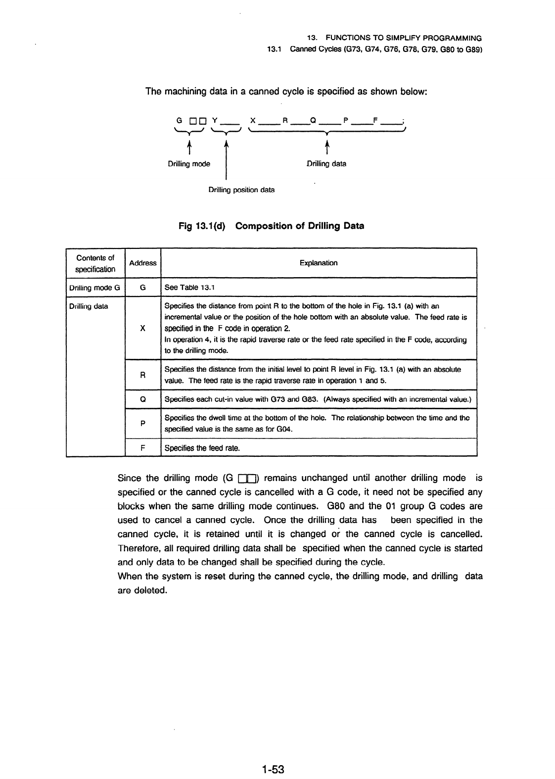
The machining data in a canned cycle is specified as shown below:
t
f
Drilling mode Drilling data
Drilling position data
Fig 13.1 (cl) Composition of Drilfing Data
Contents of
specification
Address Explanation
Drilling mode G
G
See Table 13.1
Drilling data
Specifies the distance from point R to the bottom of the hole in Fig. 13.1 (a) with an
incremental value or the position of the hole bottom with an absolute value. The feed rate is
X specified in the F code in operation 2.
In operation 4, it is the rapid traverse rate or the feed rate specified in the F code, according
to the drilling mode.
R
Specifies the distance from the initial level to point R level in Fig. 13.1 (a) with an absolute
value. The feed rate is the rapid traverse rate in operation 1 and 5.
Q
Specifies each cut-in value with G73 and G83. (Always specified with an incremental value.)
P
Specifies the dwell time at the bottom of the hole. The relationship between the time and the
specified value is the same as for GO4.
F Specifies the feed rate.
Since the drilling mode (G ITI) remains unchanged until another drilling mode is
specified or the canned cycle is cancelled with a G code, it need not be specified any
blocks when the same drilling mode continues.
G80 and the 01 group G codes are
used to cancel a canned cycle. Once the drilling data has
been specified in the
canned cycle, it is retained until it is changed or the canned cycle is cancelled.
Therefore, all required drilling data shall be specified when the canned cycle is started
and only data to be changed shall be specified during the cycie.
When the system is reset during the canned cycle, the drilling mode, and drilling data
are deleted.
l-53
Contents Summary of Power Mate D and F Motion Controllers Programming manual
- Page 1GE Fanuc Automation Motion Control Products Power Mate D and F Motion Controllers Programming Manual (Volume 1 of 2) B-62093E/03 April 1994
- Page 2GFL-001 Warnings, Cautions, and Notes as Used in this Publication Warning Warning notices are used in this publication to emphasize that hazardous voltages, currents, temperatures, or other conditions that could cause personal injury exist in this equipment or may be associated with its use. In situ
- Page 3CONSTITUTION OF THIS MANUAL This manual (B-62093E) is composed of the following 2 volumes. Vol. 7 PREFACE Power Mate-D, Power Mate-D2, Power Mate-F LIST OF SPECIFICATIONS I. PROGRAMMING PREFACE / INTRODUCTION / CONTROLLED AXES / PREPARATORY FUNCTION (G FUNCTION)/ INTERPOLATION FUNCTION / FEED FUNCTI
- Page 4PREFACE PREFACE This manual describes the following product: Name of product I Abbreviation FANUC Power Mate-MODEL D (l-path) 1 Power Mate-D FANUC Power Mate-MODEL D (2.path) Power Mate-D2 I FANUC Power Mate-MODEL F Power Mate-F This manual describes the following items related to all functions poss
- Page 5PREFACE This manual consists of the following parts: I. Programming This part mainly explains G codes used in programs and how to create CNC operation programs. CNC programmers should read this part. II. Operation This part explains typical operating procedures for the CNC and machines incorporating
- Page 6CONTENTS PREFACE Power Mate-D, Power Mate-D2, Power Mate-F LIST OF SPECIFICATIONS I. PROGRAMMING PREFACE . .... ... . .. .. ...... ... .. .. .. .. . .. ... .. . . . . .. .... ... ... .. . . . l-1 1. INTRODUCTION . . ... ..... ... ... . .. ... . .... .. . . .. . . .... . . ... .... . .. 1-2 2. CONTRO
- Page 76.3 ExampleforUsingG28andG29 ................................... l-26 6.4 Reference Point Return Check (G27) ................................. l-27 6.5 2nd 3rd Reference Point Return (G30) ............................... 1-27 7. COORDINATE SYSTEM ............................................. l-28 7.
- Page 813.1.6 G82 (drilling cycle, counter boring cycle) ....................... 1-56 13.1.7 G83 (peck drilling cycle) .................................. f-57 13.1.8 G84 (tapping cycle) ............. ‘. ........................ l-58 13.1.9 G85 (boring cycle) ...................................... I-58 13.1
- Page 916.1.1 Tool length offset A ..................................... l-114 16.1.2 Tool length offset B ..................................... l-115 16.1.3 Tool length offset C ..................................... l-117 II. OPERATION PREFACE .. . . . .. . . .. . .... .. ... . .. . . ... . ... . ... .. .
- Page 106.3 Feedrate Override ................................... ; .......... 2-38 6.4 Rapid Traverse Override ......................................... 2-39 6.5 Dry Run .................................................... 2-39 6.6 Single Block .................................................. 2-40 7. SAF
- Page 1111.4 System Parameter ............................................. 2-82 I I A.1 Parameter display ....................................... 2-82 11.4.2 Parametersetting ....................................... 2-82 11.5 Pitch Error Compensation Data .................................... 2-84 11.6 Data
- Page 1214.6 Status Display . . . . . . . . . . . . ..*................................ 2-114 15. DATA OUTPUT . . ................................................ 2-115 15.1 Output Format ............................................... 2-115 15.2 Output Method . . . . . . . . . . . . . -. . . . . . . . . _.
- Page 1319. MECHANICAL HANDLE FUNCTION .................................... 2-134 19.1 Outline .................................................... 2-134 19.2 Follow-upsignal ............................................... 2-134 19.3 InputSignal ................................................. 2-135 19.4Ca
- Page 1423.2.3.1 inputting ail data ............................... 2-169 23.2.3.2 inputting data individually ......................... 2-169 23.3 Operation ........................... 1 ....................... 2-I 70 23.3.1 Outputting data to a memory card ........................... 2-170. 23.3.2 inputti
- Page 15LIST OF SPECIFICATIONS Power Mate-D, Power Mate-D2, Power Mate-F LIST OF SPECIFICATIONS This manual describes all functions available in the Power Mate-D, Power MateD2, and Power Mate-F. See the following list of specifications for what description applies to which model. The following conventions a
- Page 16LIST OF SPECIFICATIONS Operation 0 : Standard * : Option D Item Specifications F 1-path 2-path Automatic operation (memory) 0 0 0 DNC operation 0 - 0 position setting Butt method * * * without DOG Manual handle feed 1 unit 0 0 0 2 units * - - Manual handle feed rate Xl, X10, xm, Xn 0 0 0 m: to 127,
- Page 17- LIST OF SPEClFlCATlONS Interpolation 0 : Standard * : Option D item Specifications F 1-path 2-path Positioning GO0 0 0 0 Linear interpolation Two controlled axes are 0 - - necessary. Circular interpolation Two controlled axes are 0 - - necessary. Polar coordinate interpolation Two controlled axes
- Page 18LIST OF SPECIFICATIONS Feed function 0 : Standard * : Option D Item Specifications F 1-path 2-path Rapid traverse 240 m/min or a limit imposed by 0 0 0 the increment system and the motor Rapid traverse override Fo, 25, 50, 100% 0 0 0 Rapid traverse over rap 0 .O - Feed per minute mm/min 0 0 0 Feed p
- Page 19LiST OF SPECIFICATIONS Program input Q : Standard * : Option Item Specifications El/W0 automatic recognition I O I 0 I I 0 Label skip 0 0 0 Parity check Horizontal and vertical parity 0 0 0 Control in/out 0 0 0 Optional block skip I9 I O I O I O Max. programmable dimension t 8-digit I O I O I O Prog
- Page 20LIST OF SPECJFICATIONS Auxiliary/Spindle function 0 : Standard * : Option imultaneous block star-t Rigid tap * * * Note 5 (Note 5) Rigid tapping in two-path control of the Power Mate-D is effective only for set-id output. . Tool function/Tool compensation 0 : Standard * : Option D Item Specification
- Page 21LIST OF SPEClFlCATlONS Editing operation 0 : Standard * : Option D Item Specifications F 1-path 2-path Part programming editing 0 0 0 Program protect 0 0 0 Back ground editing 0 0 Extended part program editing The CRT/MD1 and CRT module * * - are necessary. Play back 0 0 0 Ladder diagram editing The
- Page 22LIST OF SPECIFICATIONS Others 0 : Standard * : Option Item Specifications Ill F f Setting and display unit 9“ monochrome CRT/MD1 > I I * 3 1, Seprate type CRT, Separate type * 1 ‘.V.~.~.~.V.~, v.-.v.v.*, ‘.v.‘.v.~,*, ~.V,5,V.~ MD1 I I::::z$::::::::; 5fV.V.W Seprate type PDP, Separate type MDI
- Page 23I PR,oGRAMMlN
- Page 24PREFACE This part describes the items required for creating a CNC program. Chapter item Description Related code 1 Outline Functions necessary for programming 2 Controlled axes increment system and stroke 3 Preparatory function General information of G codes r 4 interpolation functions Positioning a
- Page 251. INTRODUCTION 1w INTRODUCTION (1) Axis movement-Interpolation This manual uses the following notation. . . End of block (LF for IS0 code, CR for EIA code) (a1 Positioning (GOO) Start Point 9.. Rapid traverse -. +---+C) End point GOOX --Y ; . Positioning is done by rapid traverse rate. . It is dece
- Page 261. JNTRODUCTION (a) Reference point (fixed position on machine) A CNC machine tool is provided with a fixed position. Normally, tool change and programming of absolute zero point as described later are performed at this position. This position is called the reference point. Reference point Q- / The
- Page 271. INTRODUCTION (c) Incremental coordinate values Specify the distance from the previous tool position to the next tool position. B(25,lO) X Specify the tool movement from point A to point B as follows: G91X20.OY - 20.0; (3) Cutting speed ----- Spindle function (See l-9) Workpiece The speed of the t
- Page 281,. INTRODUCTION (4 Selection of tool used for various machining - Tool Function (See i-1 0) /Tool number ATC magazine When drilling, tapping, boring, milling or the like, is performed, it is necessary to select a suitable tool. When a number is assigned to each tool and the number is specified in t
- Page 291. INTRODUCTION Block Block Block Block ’ Tool movement sequence A group of commands at each step of the sequence is called the block. The program consists of a group of blocks for a series of machining. The number for discriminating each block is called the sequence number, and the number for discr
- Page 301. INTRODUCTION Normally, a program number is specified after the CR code at the beginning of the program, and a program end code (M02, M30) is specified at the end of the program. (See I -11 MISCELLANEOUS FUNCTION) Main program and subprogram When machining of the same pattern appears at many porti
- Page 312. CONTROLLED AXES 2 l CONTROLLED AXES 2.1 Controlled Axes Number of control axis : 1 axis Number of controlled axes expanded : 1 axis(2 axes in total) (Note) Controlled-axis expansion is possible only with the Power Mate-D. 22. Name of Axes . An arbitrary name can be selected from the following : X
- Page 323. PREPARATORY FUNCTION (G FUNCTION) 3. PREPARATORY FUNCTION (G FUNCTION) A number following address G determines the meaning of the command for the concerned block. G codes are divided into the following two types. Type Meaning One-shot G code The G code is effective only in the block in which it i
- Page 333. PREPARATORY FUNCTION (G FUNCTION) I G code Group I Function I Custom-macro continuous-state call IL I Ctus om-macro continuous-state call cancellation 1 Peck drillina cvcle G74 I G76 G78 G79 1 1 1 Rigid normal threading cycle for chaser Rigid reverse threading cycle for chaser Canned cvcle cancel
- Page 344. INTERPOLATION FUNCTIONS 4.1 Positioning (GOO) 4. INTERPOLATION FUNCTIONS 4.1 Positioning (GOO) GO0 specifies positioning. A tool moves to a certain position in the work coordinate system with an absolute command or to a position specified distance from the current position with an incremental com
- Page 354. INTERPOLATION FUNCTIONS 4.2 Linear Interpolation (GO1 ) 4.2 Linear Interpolation (GOI) GOlP F ; This comman~ate~linear interpolation mode. The values of P define the distance of tool travel which will be conducted in absolute or incremental mode, according to the current status of G90IG91. For ex
- Page 364. INTERPOLATION FUNCTIONS 4.3 Circular Interpolation (GO2, G03) 4.3 Circular Interpolation (G02, G03) The command below will move a tool along a circular arc. Arc on XpYp plane R { 1 - J 1 F-i - - Arc on ZpXp plane (38 {g; 1 ZPD XP- Arc on YpZp plane G19 { z;; )YP - ZP- Xp: X axis ‘or its parallel
- Page 374. INTERPOLATION FUNCTIONS 4.3 Circular Interpolation (G02, G03) The view is from the positive direction of the Zp axis (Yp axis or Xp axis) to the negative direction on XpYp plane (ZpXp plane .or YpZp plane) in the right hand Cartesian coordinate system. YPA XPA ZPb GO3 GO3 GO3 GO2 9 GO29 % GO2 * X
- Page 384. INTERPOLATlON FUNCTIONS 4.3 Circular Interpolation (GO2, G03) In this case, two types of arcs (one arc is less than 180°, and the other is more than 180”) are considered, as shown in the example figure . When an arc exceeding 180” is commanded, the radius must be specified with a negative value.
- Page 394. INTERPOLATION FUNCTIONS 4.3 Circular Interpolation (GO2, G03) (2) In incremental programming G91 GO3 Xp-60.0 Yp 60.0 R 60.0 F300. ; GO2 Xp-20.0 Yp-40.0 R 50.0 ; or G91 GO3 Xp-60.0 Yp 60.0 I-60.0 F300. ; GO2 Xp-20.0 Yp-40.0 i-50.0 ; The feed rate in circuiar interpolation is equal to the feed rate
- Page 405. FEED FUNCTIONS 5.1 Rapid Traverse (GOO) 5. FEED FUNCTIONS . 51 Rapid Traverse (GOO) Positioning is done in rapid motion by the positioning command (GOO). There is no need to program rapid traverse rate, because the rates are set in the parameter RPDF (No. 1420). Rapid traverse rate can be overrid
- Page 415. FEED FUNCTIONS 5.2 Cutting Feed Rate (GOl) Feed speed of linear interpolation (GOl) is commanded with numbers after the F code. 52.1 Cutting feed rate clamp Cutting feed rate upper limit can be set as parameter FEDMX (No. 1422). If the actual cutting feed rate (feed rate with override) is command
- Page 425. FEED FUNCTIONS (Note) When the rotation speed of the position coder is 1 rpm or less, the feed rate becomes nonuniform. ln cases where machining is not adversely affected by feed rate nonuniformity,the position coder can be used at 1 rpm or less. Though the degree of nonuniformity differs accordi
- Page 435. FEED FUNCTIONS 5.6 Override 5.6 Override Refer to machine tool builder’s manual for details of overrides. 5.6.1 Feed rate override The feed per minute (G94) can be overridden using the switch on the machine operator’s panel by: 0 to 254% (per every 1%). Feed rate override cannot be applied to fun
- Page 445. FEED FUNCTIONS 5.7 Automatic Acceiera;tion/Deceleration 5.7 Automatic Acceleration/Deceleration 5.7.1 Automatic acceleration/deceleration after interpolation Automatic acceleration/deceleration is performed when starting and ending movement, resulting in smooth start and stop. Automatic accelerat
- Page 455. FEED FUNCTIONS 5.7 Automatic Acceleration/Deceleration Rapid traverse Rapid traverse Acceleration/ deceleration time constant of rapid Speed t-R traverse (Parameter No. 1620) -TR +j JOG feed FJ : Jog feed rate TJ.: Jog feed time constant - Speed T FJ (data No. 0529) (Parameter 1624) FL : Low feed
- Page 465. FEED FUNCTIONS 5.8 Speed Control at Comers of Blocks 5.8 Speed Control at Corners of Blocks For linear acceleration/deceleration after interpolation, the acceleration or deceleration is applied in feed start and feed stop, automatically with a time constant so that the machine tool system is not
- Page 475. FEED FUNCTIONS 5.9 Dwell (G04) 59. Dwell (G04) Wrth the GO4 command, shifting to the next block can be delayed. Shifting to the next block can be delayed for the commanded minutes. Format G94G04 P _ ; or G94GO4X ; Dwell timecommanded in seconds O.OOl- 99999.999 set When P or X is omitted, this co
- Page 486. REFERENCE POINT 6.1 Automatic Return to Reference Point (G28) 6 l REFERENCE POINT The reference point is a fixed position on a machine tool to which the tool can easily be moved by the reference point return function. Reference point . 61 Automatic Return to Reference Point (G28) G28P ; This comm
- Page 496. REFERENCE POINT 6.2 Automatic Return from Reference Point (G29) G29P ; This commandpositions the tool at the commanded position via the intermediate point of a commanded axis. In general, it is commanded immediately following G28 or G30. (2nd, 3rd return to reference point) For incremental progra
- Page 506. REFERENCEPOINT . 64 Reference Point Return Check (G27) The G27 reference point return check function checks whether or not the program returns to the reference point normally, as programmed. G27P ; This command positions the tool at rapid traverse rate. If the tool reaches the reference point, th
- Page 517. COORDINATE SYSTEM 7.1 Machine Coordinate System 7 m COORDINATE The function of the CNC is to move the machine, i.e. tool to a programmed position at a programmed rate. The position to be reached by the tool is given as a coordinate value in a coordinate system. The following two types of coordina
- Page 527. COORDINATE SYSTEM 7.2 Programming of Work Coordinate System (Gg2) 7.2 Programming of Work Coordinate System (G92) A coordinate system used for work machining is called the work coordinate system. The work coordinate system is set by using G92 command. (G90) G92P ; This commandestablishes the work
- Page 537. COORDINATE SYSTEM 7.3 Automatic Coordinate System Setting The work coordinate system is set automatically when the manual reference point return has been completed. In this case, set the distance Q to parameter PRSX, Y (No. 1250), so that the machine position (top of the standard tool or the stan
- Page 548. COORDINATE VALUE AND DlMEN$lON 8.1 Absolute and Incremental Programming (G90, G91) 8. COORDINATE VALUE AND DIMENSION 81 . Absolute and Incremental Programming (G90, GW) There are two ways to command travel of the axis; the absolute command, and the incremental command. In the absolute command, co
- Page 558. COORDINATE VALUE AND DIMENSION 8.2 Inch/Metric Conversion (020, G21) 8.2 Inch/Metric Conversion (G20, G21) Either inch or metric input can be selected by G code. Least setting Unit systems G code increment Inch G20 . 0.0001 inch Millimeter 0.001 mm I G21 I This G code must be specified in an inde
- Page 568. COORDINATE VALUE AND DIMENSION 8.3 Decimal Point Input . 83 Decimal Point Input This control can input numerical values with a decimal point. However, some addresses cannot use a decimal point. A decimal point may be used with distance, time, or speed values. The location of decimal point is mm,
- Page 579. SPINDLE SPEED FUNCTION 9.1 Spindle Speed Command 9. SPINDLE SPEED FUNCTION 9.1 Spindle Speed Command By specifying a numerical value following address S, a code signal of binary and a strobe signal is output. This is mainly used to control the spindle speed. An S code can be commanded in a block.
- Page 5810. TOOL FUNCTION (T FUNCTION) 10.1 Tool Selection Command 10. TOOL FUNCTION (T FUNCTION) 10.1 Tool Selection Command By specifying a 2-digit numerical value following address T, a binary code signal and a strobe signal are transmitted to the machine tool. This is mainly used to select tools on the
- Page 5911. MISCELLANEOUS FUNCTION I I .I Miscellaneous Function (M Function) 11 l MISCELLANEOUS FUNCTION When a move command and M codes are specified in the same block, the commands are executed in one of the following two ways: (i) Simultaneous execution of the move command and M function commands. (ii)
- Page 60I I. MISCELLANEOUSFUNCTION (4) M98: Calling of subprogram This code is used to call a subprogram. (Refer to item 12.4.1 “Subprogram control”) (5) M99: End of subprogram This code indicates the end of a subprogram. M99 execution returns control to the main program. See the subprogram control section
- Page 6112. PROGRAM CONFIGURATION 12.1 Main Program and Subprogram 12. PROGRAM CONFIGURATION 12.1 Main Program and Subprogram (1) Main program A program is divided into a main program and subprogram. Normally, the CNC operates according to the main program, but when a command calling a subprogram is encount
- Page 6212. PROGRAM CONFIGURATION 12.1 Main Program and Subprogram Main program Sub program . Sub program 02000; M98p3000; 1-loop nesting 24oop nesting A call command can call a subprogram repeatedly. A call command can specify up to 999 repeations of a subprogram. (a) Preparation of subprogram A subprogram
- Page 6312. PROGRAM CONFIGURATION 12.1 Main Program and Subprogram (b) Subprogram execution A subprogram is executed when called by the main program or another subprogram. A subprogram call has the following format: M98P 000 0000 WV Subprogram number Number of times the subprogram is to be repeated. When th
- Page 6412. PROGRAM CONFIGURATION 12.1 Main Program and Subprogram (ii) If the M99 command is executed in the main program, control returns to the start of the main program. For example, a “IM99;” block is inserted in the proper position of the main program and the optional block skip is off, M99 is execute
- Page 6512. PROGRAM CONFIGURATION 12.1 Main Program and Subprogram NO010 NO020 c NO030 NO040 Optional block NO050 skip OFF NO060 Optional block /NO070 M99P0030; skip ON NO080 ; NO090 M02; N1040 ; NI050 ; Optional block NI 060 . Y skip ON /NI 070 M02; c N1080 M99 PI050 ; 12.1.1 Program number This control ca
- Page 6612. PROGRAM CONFIGURATION 12.1 Main Program and Subprogram (Note 2) A block with an optional block skip code such as /MO2;, M30; or /M99; is not regarded as the end of a program. (Note 3) When neither program number nor sequence number are specified, a program number must be specified from the DPUMD
- Page 6712. PROGRAM CONFIGURATION 12.1 Main Program and Subprogram ;/2Nl23GOlX4 .......... ; N7856 b Range ignored 4 Example: Nl 00X1 00; /2Nl0lXl00; /2/3Nl02X200; 13Nl03X200; In the above example, the blocks of NIOI and N102 when switch No.2 is ON, and the blocks of N102 and N103 when switch No.3 is ON, ar
- Page 6812. PROGRAM CONFIGURATION 12.1 Main Program and Subprogram The address is a letter which indicates the meaning of the numerical value following the address. Addresses and their meanings are shown below. Some addresses may vary in meaning depending on preparatory functions (G code) specified in the p
- Page 6912. PROGRAM CONFIGURATION 12.1 Main Program and Subprogram 12.1.5 Basic addresses and command value range The basic addresses and command value range are listed in Table 12.4.6. Note that these figures give the maximum numerical limit, not the mechanical limit of the CNC machine tool. Under CNC cont
- Page 7012. PROGRAM CONFIGURATION 12.2 Comment Section 12.2 Comment Section The information punched between the control out and the control in codes shown below is all considered as a comment and is skipped. Since a TH check is not performed, a heading, comments, and indications for the operator can be punc
- Page 7112. PROGRAM CONFIGURATION (Example) Used as heading FlOOOCR( )NllO Significant section Name of tape, etc. Significant section (Note 1) The rewind stop code (% or ER) cannot be used in the comment section. Reading this code resets the NC. The comment section is not discriminated during rewinding the
- Page 7212. PROGRAM CONFIGURATION 12.4 Tape End 12.4 Tape End The end of a tape is indicated by punching the code below immediately following the Program End of the iast program on a tape. I EIA I IS0 1 Meaning I ER % Tape End / (Note) If MO2 nor M30 is not at the end of the program section, and ER (EIA) or
- Page 7313. FUNCTIONS TO SIMPLIFY PROGRAMMING 13.1 Canned Cycles (G73, G74, G76, G78, G79, G80 to G89) 13. FUNCTIONS TO SIMPLIFY PROGRAMMING 13.1 Canned Cycles (G73, G74, G76, G78, G79, G80 to G89) A canned cycle simplifies the program by using a single block with a G code to specify the machining operation
- Page 7413. FUNCTIONS TO SIMPLIFY PROGRAMMING 13.1 Canned Cycles (G73, G74, G76, G78, G79, G80 to G89) Operation 1 --) s1.. i i r), * l i i t-operation initial point 5 . l l : v Point R -06 A . .. .. . : -Operation 4 I Operation 2 * i. . .. l - - . -+ l Rapid traverse .. . - Feed 0’ Operation 3 Y Fig. 13.1
- Page 7513. FUNCTIONS TO SIMPLIFY PROGRAMMING 13.1 Canned Cycles (G73, G74, G76, G78, G79, G80 to G89) (Note 2) Before the drilling axis can be changed, the canned cycle must be canceled. The following description assumes that parameter FXY is set to 0 and the drilling axis is the first axis (X). A canned c
- Page 7613. FUNCTIONS TO SIMPLIFY PROGRAMMING 13.1 Canned Cycles (G73, G74, G76, G78, G79, G80 to G89) The machining data in a canned cycle is specified as shown below: f Drilling mode Drilling data t Drilling position data Fig 13.1 (cl) Composition of Drilfing Data Contents of Address Explanation specifica
- Page 7713. FUNCTIONS TO SIMPLIFY PROGRAMMING 13.1 Canned Cycles (G73, G74, G76, G78, G79.680 to G89) 13.1.1 G73 (high-speed peck drilling cycle) G73 Initial point .. A.. .. .. .. .. .. Point R i .. .. ... .. . ... 0 .. .. .. . ... .. .. + A .. ... 9 .. . .. ... .. .. .. .. .. .. t .. 9 ... .. . ... v :. ..
- Page 7813. FUNCTIONS TO SIMPLIFY PROGRAMMING 13.1 Canned Cycles (G73, G74, G76, G78, G79, G80 to G89) 13.1.2 G74 (counter tapping cycle) G74 Lj :. .. ... . 0 A point .. . .:. Initial .. .. Point R OZ P II 0 Bottom point of the hole Spindle Dwell cw At the bottom of the hole, the spindle rotates clockwise a
- Page 7913. FUNCTIONS TO SIMPLIFY PROGRAMMING 13.1 Canned Cycles (G73, G74, G76, G78, G79, G80 to G89) 13.1.4 G80 0m.m. canned cycle cancel The canned cycle (GX3, G74, G76, G81 to G89) is canceiled and normal operation is subsequently performed. The points R and bottom of the hole are also cancelled. (That
- Page 8013. FUNCTIONS TO SIMPLIFY PROGRAMMING 13.1 Canned Cycles (G73, G74, G76, G78, G79,680 to G89) 13.1.7 G83 (peck drilling cycle) G83 s . Jnitial level A. .. Point R level Bottom point of the hole G83 X Q R- F- ; The command above specifies the peck drilling cyc1e.Q is the every cut-in value and specif
- Page 8113. FUNCTIONS TO SIMPLIFY PROGRAMMING 13.1 Canned Cycles (G73, G74, G76, G78, G79, G80 to G89) 13.1.8 G84 (tapping cycle) G84 u . :. .- .. .. i 0 A point .. .. .. . :@ .. Initial .- .. Spindle CW .. s,/ Point R Bottom point II 0 of the hole P oz Spindle CCW The spindle is reversed at the bottom of t
- Page 8213. FUNCTIONS TO SIMPLIFY PROGRAMMING 13.1 Canned Cycles (G73, G74, G76, G78, G79, G80 to G89) 13.1.10 G86 (boring cycle) G86 Spindle CW CJ J . . A . . .. Initial l l l : . .:. point l l l l l .. ... l l l v . l 0 ! Point R .. .. .. .. . ... .. .. Bottom point I of the hole 0: x Spindle stop This is
- Page 8313. FUNCTIONS TO SlMPLIFY PROGRAMMING 13.1 Canned Cycles (G73, (574, G76, G78, G79, G80 to G89) 13.1.12 G88 (boring cycle) G88 \ .. Spindle CW ... f .. ... I .. . 4 Point R Bottom point of the hole @ \ Spindle stop after dwell v Manual feed 13.1.13 G89 (boring cycle) G89 L? -. ,!. Initial point ...
- Page 8413. FUNCTIONS TO SIMPLIFY PROGRAMMING 13.1 Canned Cycles (G73, G74, G76, G78, G79, G80 to G89) 13.1.14 Rigid mode To set the rigid mode, specify M29Ss %%m; before command of tapping cycle and reverse tapping cycle. By this operation, the spindle stops, the rigid mode turns on, and the rigid mode is
- Page 8513. FUNCTIONS TO SIMPLIFY PROGRAMMING 13.1 Canned Cycles (G73, G74, G76, G78, G79, G80 to G89) 13.1.15 Deep-hole rigid tap cycle G74/G84X R P Q F ; I! X_; - - - - - Rigid mode X ; The deep-hole rigid tap cycle is selected as the infeed once Q is instructed. It is possible to select either of the 2 t
- Page 8613. FUNCTIONS TO SiMPLlFY PROGRAMMING 13.1 Canned Cycles (G73, G74, 676, G78, G79, G80 to G89) (2) Deep-Hole Rigid Tap Cycle (PCP = 1) G84 Initial point .. 4 1 1 I -I II Point R 9 +d UAvA A + 9 I, ’ +d 4 9 Bottom I E, ‘- point of the hole Q represents the infeed once and is always instructed in an i
- Page 8713. FUNCTIONS TO SIMPLIFY PROGRAMMiNG 13.1 Canned Cycles (G73, G74, G76, G78, G79, G80 to G89) F ; (Driliing is not performed. Value F is updated.) M- - ; (Drilling is not performed.) (Only the miscellaneous function is executed.) G04P ; (Drilling is not performed. Drilling data P is not changed by
- Page 8813. FUNCTIONS TO SIMPLIFY PROGRAMMING 13.1 Canned Cycles (G73, G74, G76, G78, (579, G80 to G89) 13.1.17 G78, G79 (rigid threading cycle for chaser tool) Command format M29 S_; G78 XxRrQa Ff; G79 - - . G80 9 G78 : forward threading cycle G79 : reverse threading cycle G80 : -canned cycle cancel X : th
- Page 8913. FUNCTIONS TO SIMPLIFY PROGRAMMING 13.2 Programmable Parameter Entry @IO, G11) 13.2 Programmable Parameter Entry (GIO, Gl 1) Parameters can be set by tape commands. Parameters such as max. cutting speed and cutting feed time constant can be changed according to the machining conditions This funct
- Page 9014. MEASUREMENT FUNCTIONS 14.1 Skip Function (G31) 14. MEASUREMENT FUNCTIONS 14.1 Skip Function (G31) Linear interpolation can be commanded by specifying axial move following the G3l command, like GOl. If an external skip signal is input during the execution of this command, execution of the command
- Page 9114. MEASUREMENT FUNCTIONS 14.2 Multiskip Function (G31) 14.2 Multiskip Function (G31) X--- Y F ; It is possible to command linear interpolation by Pl - P4 and a move command subsequent to G31 just as in GOl. If a skip signal effective for the number specified by P is input from outside during the G3
- Page 9215. CUSTOM MACRO 15. CUSTOM MACRO A function covering a group of instructions is stored in memory the same as a subprogram. The stored function is represented by one instruction, so that only the representative instruction need be specified to execute the function. This group of registered instructi
- Page 9315. CUSTOM MACRO G65P9011AlOM; Calls custom macro body 9011 and sets variables #I and #4 tolOand5 be respectively. used instead of the unknown traverse distance. Fig.1 5 (b) Custom macro instruction and variables This means that a function of general use can be formed when programming a certain func
- Page 9415. CUSTOM MACRO 15.1 Macro Call Command (Custom Macro Command) 15.1 Macro Call Command (Custom Macro Command) A macro can be called from a single block, or modally from each block in the call mode. 151.1 Simple calis When the following command is executed, the custom macro body (for the specified b
- Page 95
- Page 9615. CUSTOM MACRO 15.1 Macro Call Command (Custom Macro Command) (Continued) Address of the argument assignment II Variable in user macro body L 15 #16 J5 #17 / K5 #18 16 #19 L J6 #20 . . K6 #21 17 #22 I J7 #23 - K7 #24 I 18 #25 J8 #26 K8 #27 19 ?F28 J9 #29 l K9 I#30 L ho #31 JlO #32 4 KIO #33 Suffix
- Page 9715. CUSTOM MACRO 15.1 Macro Call Command (Custom Macro Command) 151.2 Modal call The macro call mode can be specified by executing the following command. G66P prooram number L repetitive count
is the same as for a simple call. During the macro call - Page 9815. CUSTOM MACRO 15.1 Macro Call Command (Custom Macro Command) 15.1.3 Macro call using G codes A G code can be set by a parameter to call a macro. That is, instead of specifying N G65P AAAA
; the following simple command can be used. . N Gxx < argument assignment) ; The corre - Page 9915. CUSTOM MACRO 15.1 Macro CaJi Command (Custom Macro Command) When these M codes are specified in a macro called with a G code or in a subprogram called with an M code or a T code, the subprogram is not called, but these M codes are treated as ordinary M codes. Set parameters 6071 to 6073. 15.1.6
- Page 10015. CUSTOM MACRO 15.1 Macro Call Command (Custom Macro Command) G66 P9200; 2 15000.0; (I-2) G67; : P9200 cancelled G67; : PBlOO cancelled Z-25000.0; (‘l-3) M30; 0 9100; x 5000.0; (2-1) MBB; 0 9200; Z 6000.0; (3-1) Z 7000.0; (3-2) MBB; Sequence of execution (A block without a motion command is omitte
- Page 101IS. CUSTOM MACRO . 15.1 Macro Call Command (Custom Macro Command) The main program is provided with #1 to #33 local variables (level 0). When the macro (level 1) is called with G65, etc., the local variable (level 0) of the main program is stored, and #I to #33 local variables (level 1) for the macr
- Page 10215. CUSTOM MACRO 15.2 Creation of Custom Macro Body 15.2 Creation of Custom Wlacro Body 152.1 Custom macro body format The format of a custom macro body is as shown below. 0 lJDClCl; (Program Number) ; Commands (Variables, arithmetic operation and control instruction can be specified.) M99; Program
- Page 10315. CUSTOM MACRO 15.2 Creation of Custom Macro Body (a ) Using a variable with addresses/,:, 0 and N is prohibited, (i.e.,:#27 or N#I cannot be used). The value of n (n = I to 9) in an optional block skip/n cannot be used as a variable. (b) A variable number cannot be replaced by a variable. When 5
- Page 10415. CUSTOM MACRO 15.2 Creation of Custom Macro Body (c) Conditional expressions
differs from 0 only for EQ and NE. When #I = - Page 10515. CUSTOM MACRO 15.2 Creation of Custom Macro Body (3) Common variable adding option (HO0 - #199, #500 - #699) Optional common . variables, #IO0 to #199 and #500 to 4499 are available for both memory module B and memory module C. This option can be used to expand the number of common variables in e
- Page 10615. CUSTOM MACRO 15.2 Creation of Custom Macro Body (a) Interface signals NO00 to #I 015 and #1032, #l 100 to #1155 and #1132, #1133 [Input signal] The status of the interface input signal is determined by reading the values of the system variables NO00 to #l 015. System variable Point Interface inp
- Page 10715. CUSTOMMACRO 15.2 Creation of Custom Macro Body Output sianal Interface output signals can be issued by assigning values to system variables #I 100 to#I115, #1132,#1133. System variable Point Fi$$$gnal #llOO 1 uoooo 20 #llOl 1 UOOOl 2' #1102 1 uooo2 22 #1103 1 uooo3 23 #1104 1 uooo4 24 a105 1 uoo
- Page 10815. CUSTOM MACRO 15.2 Creation of Custom Macro Body (Example 1) (1) Macro used to read three digits of BCD data with a sign by address switching Structure of DI 2’52~42132~1 2’029 2* 27262524 23222100 )] #lo32 Use for Sign 1 O* other purposes Structure of DO 2* 27 26 25 24 23 2* 2’ 2* [;I #1132 - -
- Page 10915. CUSTOM MACRO 15.2 Creation of Custom Macro Body (b) PMC D/R area information #I200 to #I959 System variables #I200 to #I 959 can be used to write and read data to and from the PMC D/R area. The system variables are associated with the location in the D/R area, as follows: #I200 to #1219: Variabl
- Page 11015. CUSTOM MACRO 15.2 Creation of Custom Macm Body Offset number I Tool . compensation 1 #2001 .. . 99 #2009 (Note 1) System variable #2000 is read-only and always 0. (d) Alarm #3000 When detecting an error in the macro, an alarm can be generated. When an alarm number is specified in the system vari
- Page 11115. CUSTOM MACRO 15.2 Creation of Custom Macro Body The suppression of the single block stop and the wait for the auxiliary function end signal in #3003. When the following values are assigned to the system variable #3003, the single block stop function is suppressed and execution advances from one
- Page 11215. CUSTOM MACRO 15.2 Creation of Custom Macro Body Feed rate Exact stop #3004 Feed hold override check 0 0 0 0 1 X 0 0 ISI O I X I X 7 X X X 4 0: Effective, x : Suppressed (Note) The state of #3004 is cleared by resetting. (h) Variable corresponding to the setting #3005 By substitution of system va
- Page 11315. CUSTOM MACRO 15.2 Creation of Custom Macro Body (k) Modal information #4001 to #4120 Modal commands specified up to the preceding block can be determined by reading the values of the system variables #4001 to 44120. The unit specified is effec tive. Model information of System variable preceding
- Page 11415. CUSTOM MACRO 15.2 Creation of Custom Macro Body (Note 1) The tool length offset is not the in effect just before the block is executed; it is the offset for the current block. (Note 2) Skip signal position is the end point of the G31 block if the skip signal is not turned on in the block. (Note
- Page 11515. CUSTOM MACRO 15.2 Creation of Custom Macro Body ##i =#jl#k Quotient #i=#j AND#k Logical product (at every bit of 32 bits) (4) Functions #i=SIN [#j] Sine (degree unit) #i=cos [#j] Cosine (degree unit) #i=TAN [#j] Tangent (degree unit) #i = ATAN [#j] I [#cl Arctangent (degree unit) #i = SQRT [#j]
- Page 11615. CUSTOM MACRO 15.2 Creation of Custom Macro Body (5) Combination of arithmetic operations The above arithmetic operations and functions can be combined. The order of priority in an arithmetic operation is function, multiplication arithmetic then addition arithmetic. (Example 1) #i = #j + WSIN [#I
- Page 11715. CUSTOM MACRO 15.2 Creation of Custom Macro Body Operation format Average error Maximum error Type of error 8H a = b*c 1.55 x lo-‘0 4.66 x lo-‘0 Relative error a = b/c 4.66 x IO-10 1.86 x 10-g a= b 1.24x IO-‘0 1 3 . 7 3 x 10-s a a = b + c a = b - c 2.33 x lo-10 I a = SIN b 5.0 x 10-g 1.0 x 10-e A
- Page 11815. CUSTOM MACRO 15.2 Creation of Custom Macro Body For example, when the following operations are performed, #2 does not always assume 2: Nl O#l = 0.002; N20#2 = #I *1 000; N30#3 = FIX[#2]; The fraction is rounded down at the decimal point. For some error occurs in the operation in N20 and there ma
- Page 11915. CUSTOM MACRO 15.2 Creation of Custom Macro Body WHILE [ < conditional expression > ] can also be omitted as with IF, and if omitted, blocks from DO m to END m are executed eternally. WHILE [
] DO m and END m must be used as a . pair l (Example 1) #120=1; Nl WHILE [#I20 L - Page 12015. CUSTOM MACRO 15.2 Creation of Custom Macro Body DO 2; . Dd3 ; . (VeS) END 3 .I . * EhiD 2 .9 . EhiD 1 ; . Dd ranges cannot be intersected . Dd 1 ; . Dd2 .9 l (NoI - END 1 .9 . END2 ; . A iranch can be made from inside to outside a DO range. . Dd 1 ; G&O 9000; . fees) EfiD 1 ; N9:000; . A branch
- Page 12115. CUSTOM MACRO 15.2 Creation of Custom Macro Body END 1; DO 1; M98.....; (ves) END 1; 15.2.6 Macro and NC statements’ The following blocks are called macro statements. 0i Operation command (block including = ) (ii) Control command (block including GOTO, DO or END) (iii) Macro call command (block i
- Page 12215. CUSTOM MACRO 15.2 Creation of Custom Macro Body (Example 2) N 1 GO1 Xl 000; Block currently executed N2#1100=1; Macro statement executed N3#1= 10; Macro statement executed Execution of N2 N3 maera I . statements Execution of Nl NC statmentt g Time 152.7 Codes and words used in custom macro The f
- Page 12315. CUSTOM MACRO 15.3 Registration of Custom Macro Body 15.3 Registration of Custom Macro Body A custom macro body is similar to a subprogram; it is registered and edited in the same way as a subprogram. The memory used to register custom macro bodies is included in the storage capacity of the CNC.
- Page 12415. CUSTOM MACRO 15.4 Limitations 15.4 Limitations (1) Sequence number search Sequence numbers in the custom macro body cannot be searched for. (2) Single block A block, other than one including a macro call command, arithmetic command, or control command, can be executed as a single block stop even
- Page 12515. CUSTOM MACRO 15.4 Limitations . ( c 1 Constant value valid in < Formula > Maximum value 2 99999999 Minimum value 2 0.0000001 Decimal point can be used Arithmetic precision Eight-digit decimal number Macro nesting Maximum of four (0 Iteration identification number 1 to 3 (9) Nesting of Maximum of
- Page 12615. CUSTOM MACRO 15.5 External Output Commands 15.5 External Output Commands The following macro commands can be executed in addition to the standard custom macro commands. (These commands are called external output commands.) (a) BPRNT (b) DPRNT (c) POPEN (d) PCLOS These commands are provided to ou
- Page 12715. CUSTOM MACRO 15.5 External Output Commands (iii) EOB code is output by setting data IS0 on the parameter screen after the command data output. (iv) “vacant” variable is outputtable as 0. (b) DPRNT [a #b 1 cdl . ..I.... 1 Number of digits below decimal point Number of digits above decimai point V
- Page 12815. CUSTOM MACRO 15.5 External Output Commands (Example 2) DPRNT [53] TK30 [20]] Variable value #2 = 128.47398 #5= - 9 1 . 2 #30 = 123.456 @ Parameter PRT = 0 @ Parameter PRT = 1 --- (3) Close command PCLOS PCLOS ; This command is specified when all data output commands are completed, to reiease the
- Page 12915. CLJSTOM MACRO 15.5 External Output Commands After the data is output by ISO, it is S8l8Ct8d whether only ‘LF” is output or “LF” and “CR” are output. I piiq NCR 7 6 5 4 3 2 1 0 NCR 1: “LF “and “CR” are output after the data is output. 0: Only “LF” is output after the data is output. (5) Cautions
- Page 13015. CUSTOM MACRO 15.6 Pattern Data Input Function 15.6 Pattern Data Input Function This function -enables the. user to create CNC programs only by selecting numeric data (pattern data) from drawings and entering the data through the CRT/MD& without using the conventional CNC language. For example, t
- Page 13115. CUSTOM MACRO 15.6 Pattern Data Input Function (1) Macro instruction to specify menu titles Menu titles: 1 C2 C3 C4 C5 C6 C7 C8 C9 C 10 C 11C Cl2 Each of Cl to Cl2 represents a character of a menu title. (12 characters) Macro instruction G65 H90 P~Qg_RrIiJj_Kk H90: Indicates a menu&e. p = When th
- Page 13215. CUSTOM MACRO 15.6 Pattern Data Input Function i: When the codes for characters C5 and Cs are as and as: i=a+lO3+a6 . J : When the codes for characters CT and C8 are a7 and a& j=a7x103+as k: When the codes for characters Cg and Cl0 are as and alo: k=agx103+ajc (Example) When the pattern name of t
- Page 13315. CUSTOM MACRO 15.6 Pattern Data Input Function 156.2 Displaying pattern data items When the pattern menu is selected, the data items required for the pattern are displayed. (According to the selected pattern No., the variable specified in one of parameters &0280 to &0289 is displayed first. VAR.
- Page 13415. CUSTOM MACRO 15.6 Pattern Data Input Function k: When the codes for characters Cl 1 and Cl2 are al 1 and a12: . k=all x103+a12 (Example) When the pattern data title is BORING CYCLE, the macro instruction is as follows: G65 H92 P 066 079 Q 082 073 R 078 071 BO RI NG I- 032 067 J 089 - 067 K 076 0
- Page 13515. CUSTOM MACRO 15.6 Pattern Data Input Function (hampie) Men the comment is ‘BORING CYCLE, the macro instruction is as follows: G65 H 9 4 P 042 066 Q 079 082 R -073 078 I 071 032- ; *B OR IN G G65 H 9 4 067 089 J - I- 067 076 K 069 042 ; CY CL E* (4) Example of the custom macro for the above scree
- Page 13615. CUSTOM MACRO 15.6 Pattsm Data Input Function Table 15.6.2 (a) Sub-programs used in the pattern data input function c I Sub-program No. Function r-----G-- 1 Specifies the character string for the pattern menu. --I 09501 Specifies the character string of pattern data corresponding to pattern 1. 09
- Page 13716. COMPENSATION FUNCTION 16.1 Tool Length Offset (G43, GM, G49) 16. COMPENSATION FUNCTION 16.1 Tool Length Offset (G43,G44,G49) 16.1 .l Tool length offset A This function can be used by setting the difference between the tool length assumed during programming and the actual tool length of the tool
- Page 138
- Page 13916. COMPENSATION FUNCTION 16.1 Tool Length Offset (G43, G4-4, G49) (2) Direction of offset G43 . . . . . . . . . . + side offset G44 . . . . . . . . . . - side offset In any case of absolute or incremental commands, the offset amount that has been set into the offset memory assigned by H code is in
- Page 14016. COMPENSATION FUNCTION 16.1 Tool Length Offset (G43, G44, G49) 16.1.3 Tool length offset C G43 and G44 are used to set the CNC unit in the tool length offset mode. The axis address CT specified in the G43 or G44 block specifies the axis to which the tool length offset is applied. G43 GM ‘mH- ; (C
- Page 1412nd, 3rd reference point return (G30) . . . . . . . . . . . . . . . . . . . . . . . . . . . . . . . . . . . . . . 1-27 A&olute and incremental programming (G90, G91) ............................ 1-31 Actions required for alarms .............................................. 2-42 Actual feedrate disp
- Page 142Controlcommand . . . . . . . . . . . . . . . . . . . . . . . . . . . . . . . . . . . . . . . . . . . . . . . . . . . . . 1-95 Controlled axes . . . . . . . . . . . . . . . . . . . . . . . . . . . . . . . . . . . . . . . . . . . . . . . . . . . . . . . l-8 Coordinate system ..........................
- Page 143DPUMDI panel ...................................................... 2-11 DPUMDI panel, CRT/MD1 panel .......................................... 2-11 Dry run . . . . . . . . . . . . . . . . . . . . . . . . . . . . . . . . . . . . . . . . . . . . . . . . . . . . . . . . . . . . 2-39 Dwell(G04) . . . .
- Page 144% 3 5 z 3 E l- l- s Z% 2wz a 83% I l- r m r L v=- & r- & v- I %- 5 dl &4 ‘9-F F&& 4 &JG . . l . . . . . . . . . . a .. . . . . . . . . .. . . . . .. . . . . . . . . . . 0 . . . . . . . . . . . . . . . . . .. . . . .. .. l . . . . . . . . . . . . . . . . . . . . . .. . . . .. . . e . . . 0 . . . . .
- Page 145Manual handle feed . . . . . . . . . . . . . . . . . . . . . . . . . . . . . . . . . . . . . . . . . . . . . . . . . . . . 2-29 Manual operation ..................................................... 2-23 Manual reference pOSitiOn r8tUfn ........................................... 2-23 Maximum stroke
- Page 146Parameter display .................................................... 2-82 Parameter setting .................................................... 2-82 Parameters . . . . . . . . . . . . . . . . . . . . . . . . . . . . . . . . . . . . . . . . . . . . . . . . . . . . . . . . . 2-91 Pati program stora
- Page 147Res*ictions ........................................................ 2-166 Rigidmode . . . . . . . . . . . . . . . . . . . . . . . . . . . . . . . . . . . . . . . . . . . . . . . . . . . . . . . . . I-61 Run and stop of sequence program (RUN/STOP) . . . . . . . . . . . . . . . . . . . . . . . . . .
- Page 148amd= * m @?@Pr r v- $3’ B 3 f?8 haI ?’ K? cur7 T=- v- r 8 v- a v- P 8 v= F= F x F -; T- A’ ’ . . . .. .. 0 . . a . . . . . . . . . . . . e . . . .. . . . . . .. .. . . . . . . . . . . . . . . . . . . .. . . . .. .. . . . . . . 0 . . . . . . . . 0 . . . .. .. . . . . . . . . . . . . .. l . . . . . .
- Page 149Revision Record FANUC Power Mate-MODEL D/F PROGRAMMING MANUAL (B-62093E) ’ Addition of Power Mate-D2 l Addition of Power Mate-F l Correction of errors 03 Apr., ‘94 l The Parts “Connection”, “PMC Interface”, and “Maintenance” shifted to “Connection/Maintenance Manual”. 02 Nov., ‘93 l “Data input/outp
- Page 150· No part of this manual may be reproduced in any form. · All specifications and designs are subject to change without notice.
- Page 151GE Fanuc Automation Motion Control Products Power Mate D and F Motion Controllers Programming Manual (Volume 2 of 2) B-62093E/03 April 1994
- Page 152GFL-001 Warnings, Cautions, and Notes as Used in this Publication Warning Warning notices are used in this publication to emphasize that hazardous voltages, currents, temperatures, or other conditions that could cause personal injury exist in this equipment or may be associated with its use. In situ
- Page 153CONSTITUTION OF THIS MANUAL It II II I’ This manual (B-62093E) is composed of the following 2 volumes. II If VOL 1 PREFACE Power Mate-D, Power Mate-D2, Power Mate-F LIST OF SPECIFICATIONS I. PROGRAMMING PREFACE/INTRODUCTION/CONTROLLED AXES / PREPARATORY FUNCI7ON (G FUNCI?ON)/INTERPOL.!WION FUNCTION
- Page 154PREFACE PREFACE - This manual describes the foliowing product: Name of product Abbreviation FANUC Power Mate-MODEL D (1 -path) Power Mate-D FANUC Power Mate-MODEL D (2.path) Power Mate-D2 FANUC Power Mate-MODEL F Power Mate-F This manual describes the following items related to all functions possibl
- Page 155PREFACE This manual consists of the following parts: I. Programming This part mainly explains G codes used in programs and how to create CNC operation programs. ’ CNC programmers should read this part. il . Operation This part explains typical operating procedures for the CNC and machines incorporat
- Page 156. CONTENTS PREFACE Power Mate-D, Power Mate-D2, Power Mate-F LIST OF SPEClFlCATlONS I. PROGRAMMING PREFACE .. . . . .... . .. . . .. ... .. .. .... .. . . .. ... .. .. ..... . .. . .. ... .. .. . 1-1 1. INTRODUCTlON .. .. . . .. . ... ... . ... ... . . . .. ..:. . . ... .. . . . . . . ... .. . . 1-2
- Page 1576.3 Example for Using G28 and G29 ................................... l-26 6.4 Reference Point Return Check (G27) ................................. I-27 6.5 2nd,3rdReferencePointRetum(G30) ............................... l-27 7. COORDINATE SYSTEM ............................................. l-28 7.
- Page 158
- Page 159
- Page 160
- Page 161
- Page 162
- Page 163
- Page 164
- Page 165
- Page 166PREFACE Displaying and setting data for each path With the Power Mate-D2, you can display and set data for each path in the same way as with the Power Mate-D. Either signals supplied to the NC from the PMC or key operations are used to select the path for which data is displayed and set. For the CRT
- Page 167PREFACE 2. Because there is only one PMC, it is displayed and set for two paths’ in common. 3. Data inputloutput with the FANUC floppy Cassette cannot be performed for two paths simultaneously, because it has only one input/output port. 4. Usually, signals input to the NC from the PMC are used to se
- Page 1681. INTRODUCTION INTRODUCTION (1) Manual operation (a) Manual reference position return (See Section 11-4.1) The CNC machine tool has a position used to determine the machine position. This position is called the reference position, where the tool is replaced or the coordinate are set. Ordinarily, af
- Page 1691. INTRODUCTION (b) The tool movement by manual operation Using operator’s panel switches, pushbuttons, or the manual handle, the tool can be moved along each axis. MUlUal 0peratofs panel handle 0 0 0 0 8 0 I I I 00 ’ ” I WorkpieCe I Fig. 1 (b) Tool Wlovement by Manual Operation The tool can be move
- Page 1701. INTRODUCTION (2) Tool movement by programing - Automatic operation (See Section H-5) Automatic operation is to operat6 the machine according to the created program. It includes AUTO operations. . Pmgfam 01000 ; M-S-T- ; G92X- ; GOO. . .; Gol.. . . . .; . . Fig. 1 (c) Tool Movement by Programming
- Page 1711. INTRODUCTION (3) Automatic operation 0i Program selection Select the program used for the workpiece. Ordinarily, one program is prepared for one workpiece. If two or more programs are in memory, select the program to be used, by searching the program number (Section N-9.4). 01001 - Program number
- Page 1721. MRODUCTION 0 Program test (See Chapter 11-6) Before machining is started, the automatic running check can be executed. It checks whether the created program can operate the machine as desired. This check can be accomplished by running the machine actually or viewing the position display change (w
- Page 1731. INTRODUCTION (iii) Single block (See Section 11-6.7) ‘When the cycle start pushbutton is pressed, the tool executes one operation then stops. By pressing the cycle start again, the tool executes the next operation then stops. The program is checked in this manner. Fig. 1 (k) Single Block (b) How
- Page 1741. INTRODUCTION (5) Part program editing (See Section II-S) After a created program is once registered in memory, -it can be corrected or modified from the DPUMDI or the CRT/MD1 panel. Program registration Program amection or modification CRT/MD1 or ~ CNC tapt (PtogW . FQ. 1 (m) Part Program Editing
- Page 1751. INTRODUCTION (7) Notes on power-on operation (see H-3) When pressing the
- Page 1762. OPERATIONAL DEVICES 2.1 DPUMDI Panel, CRT/J401 Panel 2 l OPERATIONAL DEVICES Three kinds of operational devices are available: (1) DPUMDI panel (or CRT/MD1 panel) attached to the CNC (2) Machine Operations Ptiel (3) Exterai I/O devices (tape reader, PPR, Floppy cassette) 2.1 DPUMDI Panel, CRWMDI
- Page 1772. OPERATlONAL DEVICES . 2.1 DPUMDI Panel, CRT/MD1 Panel (1) Function keys Function keys indicate large items like chapters in a document.
indicates the current position. < PRGRM ) Conducts the following: In EDIT mode .. . edits and displays the program in the memory In automatic operation . . - Page 1782. OPERATIONAL DEVICES 2.1 DPUMDI Panel, CRT/MD1 Panel 21.2 CFWMDI Panel ~Acldresshumber keys @ Function keys I Fig.21 -2 CRT/lUlDIPanel (1) Keyboard functions Table 21.2 MD1 Keyboard functions (l/2) No . Name Functions (1) < RESET) key ‘Press this key to reset the CNC, to cancel an alarm, etc. (2)
- Page 1792. OPERATIONAL DEVICES . 2.1 DPIJMDI Panel, CRT/MD1Panel Table 21.2 MDI Keyboard functions (2I2) No. Name Functions (7) Cancel
- Page 1802. OPERATiONAL DEVICES 21 DPUMDI Panel, CRT/MD1 Panel (3) Chapters (screens) included in < OFFSET/ SETTING) function key (a) [OFFSET] Tool offset display screen (b) [SETING] Parameter setting display screen (c) [MACRO] Macro variable value display screen (d) IMEW Pattern data display screen (e) IOW
- Page 1812. OPERATIONAL DEVlCES 2.1 DPUMDI Panel, CRT/MD1 Panel 2.1.4 Chapter selection soft key configuration This soft key executes screen selection. When there is a screen that can be subdivided within a single screen, it is possible to make the selection with the chapter selection soft key. When there is
- Page 1822. OPERATIONAL DEVICES 2.1 DPUMDl Panel, CRT/MD1 Panel (4) < SYSTEM ) 4 PARAMOGNOS PMC’ SYSTEM (OP#T) b+ \ I 4 MEMORY PmCH SV.PRM SP.PRM (OPRT) be SPwSW SP.TUN SP.MON (5)
- Page 1832. OPERATIONAL DEVICES 2.2 Machine Operator’s Panel 22 Machine Operator’s Panel The operator’s panel varies in functioning and switch arrangement between the different tools. Operations of a typical operator’s panel are explained as shown Fig. 2.2. However, for details, refer to the manual issued by
- Page 1842. OPERATIONAL DEVICES 2.2 Machine @mat&s Panel Table 22 Element functions Name I Function Cycle start button By selecting an execution program then pressing this pushbutton, automatic operation is started. During automatic operation, the lamp indicating automatic operation is on. Feed hold button W
- Page 1852. OPERATlONAL DEVICES 2.3 FANUC Floppy Cassette 23. FANUC Floppy Cassette Data can be stored in the floppy cassette and also data can be input to the CNC. The interface is reader/puncher interface. Connect the floppy disk drive to connector JD5 of the Power Mate controller via the punch panel. Refe
- Page 1862. OPERA7lONAL DEVICES 2.4 FANUC PPR 2.4 FANUC PPR FANUC PPR is an VO device with paper tape reader, tape punch, and printer in one system. Interface is reader/puncher interface. Connect the FANUC PPR to the connector JD5 of the Power Mate controller through the punch panel. Reel unit I PIper tape p
- Page 1873. POWER ON/OFF 3. POWEI? ON/OFF (1) Turning on the power @ Check that the appearance of the CNC machine tool is normal. (For example, check that front door and rear door are closed.) @ Turn on the power according to the manual issued by the machine tool builder. 0 Check that some data is being disp
- Page 1884. MANUAL OPERATION 4.1 ManualReference Position Return 4 l MANUAL OPERATION 41 . Manual Reference Position Return 0 Set the MODE SELECT switch to the JOG position. , MDI . AUTO STEP/HANDLE EDIT JOG/HANDLE MODE SELECT Switch @ Turn on the REFERENCE POSITION RETURN switch. @ Jog Feed to reference pos
- Page 1894. MANUAL OPERATION 4.1 Manual Reference Position Return @ The machine stops at the reference position lighting the REFERENCE POSITION RETURN COMPLETION LED. REFERENCEPOSITION RETURNCOMPLETION LED (Note I) Once the REFERENCE POSlTlON RETURN COMPLETION LED lights at tk completion of reference positio
- Page 1904. MANUAL OPERATION 4.2 Manual Continuous Feed 42 . Manual Continuous Feed The machine tool can be continuously moved manually as follows. @ Set the MODE SELECT switch to the JOG position. AUTO S~EPIHAkDLE EDIT JOG/HANDLE MODE SELECT Switch @ Select an axis to be moved. +Y 6 0 The machine moves in t
- Page 1914. MANUAL OPERATlON 4.2 Manual ContinuousFeed @ Rapid traverse To execute the rapid traverse by manual mode, push RAPID TRAVERSE button, too. 0 RAPID TRAVERSE It is possible to move the axis in the selected direction at rapid traverse while this button is pushed. (Note) Feedrate, time constant and m
- Page 1924. MANUAL OPERATION 4.3 Step Feed (STEP) 43. Step Feed (STEP) @ Set MODE SELECT switch to position. MDI AUTo n STEP/HANDLE EDIT JOG/HANDLE MODE SELECT Switch @ Select the desired amount of movement. Xl xl000 MOVEMENT SELECT Switch Table 4.3 Step feed amount II Selection xl 11 I 0.001 mm 1 0.0001 inc
- Page 1934. MANUAL OPERATION 4.3 Step Feed (STEP) (Note 1) The feedrate is the same as the jog feedrate. (Note 2) The rapid traverse button is also effective. Rapid traverse override is e’btive during rapid traverse. 2-28
- Page 1944. MANUAL OPERATION 4.4 ManuaJ Handle Feed 4.4 Manual Handle Feed The feedrate can be adjusted precisely by using the manual pulse generator. @ Set the MODE SELECT switch to the HANDLE position. MDI STEP/HANDLE JOG/HANDLE Ci3 Select an axis. Axis select switch @ Rotate the handle of the manual pulse
- Page 1954. MANUAL OPERATION 4.4 Manual Handle Feed @ Select the movement amount Some operator’s panels are provided with the following selector switch. X10 multiplies the movement amount by 40; X100 by 100. X10 (Note 3) Xl woo ti x 1000 (Note 3) Handle Muftiplier Input System Input system x 1 x 10 x 100 x 1
- Page 1965. AUTOMATlC OPERATION 5.1 Operation Mode 58 AUTOMATIC OPERATION 51. Operation Mode 5.1. I AUTO operation Load a program to the memory (U-9.1) Select a program to be operated (U-9.2) Set the mode seiector to the AUTO position. STEP/HANDLE JOG/HANDLE (MODE SELECTOR) Press the cycie start button. 0 -
- Page 1975. AUTOMATIC OPERATION 5.1 Operation Mode (b)Select the MDI program screen. The following screen appears (for the CRT/MDl). PROGRAM (Mof) 00010 NO002 - *Q@@@$$$ GO0 G90 G21 680 G67 G17 G94 G49 G98 B H M T D F S 1 -MD1 t+tr at+ ++r(l 20:40:05 [ PRGRM ] ~$$@$.@!$ ...............*] [ CURRNT ] [ NEXT ]
- Page 1985. AUTOMATIC OPERATiON 5.1 Operation Mode (Note 3) To erase all created programs, input: 0 < DELFT> Alternatives, set parameter MCL (bii 7 of parameter No. 3203) to 1. All programs are then erased when the system is reset 2-33
- Page 1995. AUTOMATIC OPERATION 5.2 Starting Automatic Operation 5.2 Starting Automatic Operation (1) AUTO operation 0 Select the AUTO mode. 8 Select a program to be operated. 0 Press the cycle start button on the machine operator‘s panel. (2) MDI operation ( 1 Executing a program a PROGRAM :_. .._. ........
- Page 2005. AUTOMATIC OPERATION (iv) Programs created in MDI mode are deleted when: (1) M02, M30, or ER (%) is executed in MDI operation. (2) Memory operation is performed in AUTO mode. (3) The program is edited in EDIT mode. (4) Background editing is performed. (v) If the program is edited when MDI operatio
- Page 2015. AUTOMATIC OPERATION 5.4 Stopping Automatic Operation 54. Stopping Automatic Operation There are two means to stop the automatic operation. One is to command a stop command in a program where the execution is to be stopped (See 5.4.1 - 5.4.3) and the other is to stop the operation at any time by p
- Page 2025. AUTOMATC OPERATION 5.4 Stopping Automatic Operation When pressed, the feed hold lamp lights and the cycle start lamp turns off. 0 N- Turns off Cycle start At this time, 0i Feeding stops if the tool is moving. . (ii) Dwell execution . stops, if executing. (iii) M, S, or T operation continues up to
- Page 2036. TEST OPERATION 6 l TEST OPERATION 61 . Machine Lock \Nhen the switch is set to the MACHINE LOCK (MLK) position, move command pulses are suppressed. Consequently the position display is updated as specified by the program, but the tool does not move. The M, S, and T are executed. OFF Machine lock
- Page 2046. TEST OPERATION . 64 Rapid Traverse Override 25 50 69 100 F” The rapid traverse override switch of lOO%, SO%, 25% and F (settled by the machine) is provided. Overridden speed are as foliows: (1) Rapid traverse by GOO. (2) Rapid traverse durin$ canned cycle. (3) Rapid traverse in G27 and G28. (4) M
- Page 2056. TEST OPERATION 6.6 Single Biock 66. Single Block This function stops the machine after executing one block of the program. (1) Set the single block switch to ON. ON OFF @ Single block (SBK) One block of the program is executed, and then the execution is stopped. If the cycle start button is press
- Page 2067. SAFER FUNCTIONS .I 7. SAFETY FUNCTIONS 7.1 Emergency Stop ‘If you press Emergency Stop button .on the machine operator’s panel, the machine movement stops in a moment. Red EMERGENCY STOP This button is locked when it is pressed. Although it varies with the machine tool builder, the button can usu
- Page 2078. ACTIONS REQUIRED FOR ALARMS 8. ACTIONS REQUIRED FOR ALARMS In case of abnormal operation, check the items described below. (1) If an error code is displayed on the DPL or CRT screen In particular, when an error code from 000 to 232 is displayed, the error is related to the program itself or the s
- Page 2089. REGISTERING,EDiTING, AND OUTPUTTINGPROGRAMS 9.1 RegisteringPrograms 9 l REGISTERING, EDITING, AND OUTPUTTING PROGRAMS This chapter explains how to register, edit, and output programs. If the background editing is specified, a program can be registered, edited, or output while another program is b
- Page 2099. REGISTERING, EDITING, AND OUTWTllNG PROGRAMS 9.1 Registering Programs (2) Registering several programs I I I I I 01111 ... ... . M02; 02222 . ...... M30; 03333 ..... . . M02; ER (%) Data is read up to ER, and thus multiple programs are registered using the same operation as described in 1) above.
- Page 210g. REGISTERING,EDITING,AND O~U-I-WG PROGRAMS 9.1 RegisteringPrograms 9.1.4 Program registration in the background The method of registration operation is the same as the method of foreground operation. However, this operation registers a program in the background editing area. As with edit operation
- Page 2119. REGISTERING, EDITING, AND OUTPU-i’?lNG PROGRAMS 9.1 Registering Pmgrams The program of the above example is stored in the following procedure. (1) Set the setting parameter “SEQ” to 1 (For the incremental value parameter, “1 n is assumed.) (2) Select the TEACH IN STEP/HANDLE mode. (3) Make positi
- Page 212g. REGISTERING, EDITING, AND OUTWfTING PROGRAMS 9.2 Editing Programs 9.2 Editing Programs Section 9.2 explains the program editing operations indicated by the dotted box below. Registration Editing ~~~~~~~~~~~~~~~~~~---------~~~~-~~~~~~~~~~~~~~ r -------I------ 7 I c I I Program number search: See S
- Page 2139. REGISTERING,EDITING, AND OUTPUrrING PROGRAMS 9.2 Editing Programs (c) Method 3 This method searches fol the program number (0001 to 0255) corresponding to a signal on the machine tool side to start automatic operation. Refer to the relevant manual prepared by the machine tool builder for detailed
- Page 2149. REGISTERING,EDITING, AND OLJTPUI-I-INGPROGRAMS 9.2 Editing Programs (Example) Sequence number 2346 in a program (00002) is searched for. Program 00001; N1234 X100.0 Y100.0 s12; . Selected program - 0002; This section is searched * N2345 X20.0 Y20.0; starting at the beginning. Target sequence - N2
- Page 2159. REGISTERING, EDITING, AND OUTPUTTING PROGRAMS 9.2 Editing Programs (4 Inserting, altering, and deleting a word The contents of a program registered in memory can be modified. 0 Select EDIT mode. @ Press
. @ Select a program to be edited. If a program to be edited is selected, perform the op - Page 2169. REGISTERING,EDITING, AND OUTPUrrING PROGRAMS 9.2 Editing Programs Program 00050 N1234 00050 ; ...f. :::*........:p. ....*:. ..a... .....+y .....:*:*: .. Nl234 X100.0 $@#&fj$&& .,.......‘......-..f....... ; s12 ; N5678 MO3 ; MO2 ; % Holding down the cursor key < *) or < *> scans \?rords continuous
- Page 2179. REGISTERING, EDITING, AND OUTFV’TTING PROGRAMS 9.2 Editing Programs (iii) Address search method This method searches forward for a specified address, starting at the current position. (Example) Searching for MO3 Program 00050 N1234 00050 ; :s:,..:...:.:.-.:.....:.~ Nf234 is being searched @@&#$ ;
- Page 2189. REGISTERING, EDITING, AND OUTPUrrING PROGRAMS 9.2 Editing Programs (b) Inserting a word @ Search for or scan the word immediately before a desired word insertion location. @ Key in an address where a word is to be inserted. @ Key in data. @ Press the
key. (Example) inserting Tl5 0 T15 is - Page 219. 9. REGISTERING, EDITING, AND OUTFWTTING PROGRAMS 9.2 Editing Programs --- . Program 00050 N1234 00050 ; N1234 X100.0 Y1250.0 Ml5 ; 44 - Tl5 is inserted. s12 ; N5678 MO3 ; MO2 ; % (d) Deleting a word 0 Search for or scan a word to be deleted. @ Press the < DELETE> key. (Example) Deleting Xl 00.0 0
- Page 2209. REGISTERING, EDITING, AND OUTPLJTTING PROGRAMS 9.2 Editing Pmgrams (e) Deleting a block The procedure below deletes a block up to its EOB code; the cursor advances to the address of the next word. 0 Search for or scan address N for a block to be deleted. @ Key in
. @I Press the key. - Page 2219. REGISTERING, EDITING, AND OUlPU-iTtNG PROGRAMS 9.2 Editing Programs (f) Deleting multiple blocks The blocks from the currently displayed word to the block with a specified sequence number can be deleted. @ Search for or scan the first block of a portion to be deleted. @ Key in address N for the l
- Page 222g. REGISTERING,EDITING, AND OUTPU=TlNG PROGRAMS 9.2 Editing Programs Automatic sequence number insertion When a program is created using the MDI keys in EDIT mode, a sequence number can be automatically inserted to each block. A sequence number incremental value is to be set in a parameter (No. 3216
- Page 2239. REGISTERING, EDITING, AND OUTPUTI-ING PROGRAMS 9.2 Editing Programs 9.22 Editing custom macros (1) Deleting, altering, and inserting a program Men editing a custom macro already entered, the user can move the cursor to each editing unit that starts with any of the following characters and symbols
- Page 2249. REGWERING, EDITING, AND OUTPUTTING PROGRAMS 9.2 Editing Programs (Note 2) The characters 0 and space can be used for a comment Note, however, that these characters omitted when entered by pressing the
k&y more than once. (Note 3) In ( ), the characters 0 and N cannotbe followedby a perio - Page 2259. REGISTERING, EDITING, AND OUTPlJJllNG PROGRAMS 9.3 Outputting Programs from CNC 8.3 Outputting Programs from CNC 9.3.1 Output to NC tape (punch operation) Punching a program A program registered in memory can be punched using the procedure below. Set the output device ready for punch operation. S
- Page 226.. 9. REGISTERING, EDITING, AND OUJW?TNG PROGRAMS 9.3 Outputting Programs from CNC 9.3.2 Punching a program in the background A program is punched in the background in the same way as in the foreground. This particular function can also punches out the program currently selected in the foreground. C
- Page 22710. REGISTERING, EDITING, AND1 1OUTPUTTING PROGRAMS (DPUMDI) 10.1 Registering Programs 10. REGISTERING, EDITING, AND OUTPUTTING PROGRAMS (DPUMDI) This chapter explains how to register, edit, and output programs. If the background editing option is specified, a program can be registered, edited, or o
- Page 22810. REGISTERING, EDITING, AND OUTPUTTING PROGRAMS (DPUMDI) 10.1 Registering Programs (2) Registering several programs 01111 . . .. . .. M02; 02222 . ...... M30; 03333 .... . .. M02; ER’ (%) Data is read up to ER, and thus multiple programs are registered using the same operation as described in (1)
- Page 229lo. REGISTERING, EDITING, AND OUTPUTTING PROGRAMS (DPUMDI) 10.1 Registering Programs 10.1.3 Registration from MDI Select EDIT mode. Press the < PRGRM) key. Key in address 0. Enterthe number of the program to be registered. Press the < lNSRT> key. By pressing this key, the entered program number will
- Page 23010. REGISTERING, EDITING, AND OUTPUITING PROGRAMS (DPUMDI) 10.1 Registering Programs (Example) 01234 Nl GWX -;- l .* PO N2 GOOX -;.- ... Pl N3 GOlX -F300;- l 0. P2 N4 M02; PO Pl P2 o- -----~~I---+---0 The program of the above. example is stored in the following procedure. (1) Set the setting paramet
- Page 23110. REGISTERING,EDITING, AND OUTPU-fllNG PROGRAMS (DPVMDI) 10.2 Editing Programs 10.2 Editing Programs Section 10.2 explains the program editing operations indicated by the dotted box below. ~------LIIIIII- I m Registration Editing I) 2) 3) ~~~~~~~~~LII~~~~~~~--~~~~~~~~~~~~~~~~~~~~~~~~~~ Program num
- Page 232lo. REGISTERING,EDITING,AND OUTPU-IVNG PROGRAMS (DPUMDI) 10.2 Editing Programs w Method 3 This method searches for the program number (0001 to 0255) corresponding to a signal on the machine tool side to start automatic operation. Refer to the relevant manual prepared by the machine tool builder for
- Page 23310. REGISTERING,EDITING, AND OUTPUTTING PROGRAMS (DPVMDI) 10.2 Editing Programs (Example) Sequence number 2346 in a program (00002) is searched for. Program 00001; N1234 X100.0 Y100.0 s12; Selected program - 0002; This section is searched N2345 X20.0 Y20.0; c starting at the beginning. Target sequen
- Page 234IO. REGISfERING, EDITING,AND OUTPUTTING PROGRAMS (DPUMDI) 10.2 Editing Programs (4) Inserting, altering, and deleting a word The contents of a program registered in memory can be modified. Select EDIT mode. Press < PRGRM). Select a program to be edited. If a program to be edited is selected, perform
- Page 23510. REGISTERING, EDITING, AND OUTPU7TlNG PROGRAMS (DWMDI) 10.2 Editing Programs (b) Push the
button N1234X100.O;S11; N5678M03; 1 I The cursor moves backward word by word on the screen; the cursor is displayed at the address character of a selected word. (Example) I N1234 .... ... . Y125 - Page 236lo. REGISTERING, EDlTING, AND OUTPUlTING PROGRAMS (DPUMDI) 10.2 Editing Programs (iii) Search for addresses only A specified address is &arched for from the current position in the forward direction. (Example) Search for MO3 N1234X100.0; N5678M03; A Current searched/scanned MO3 to be searched word (
- Page 23710. REGISTERING, EDITING, AND OUTPUrrING PROGRAMS (DPLMDI) 10.2 Editing Programs (4) Push
key After Tl5 is inserted (Note) The last word of a block can be inserted as foliows: Key in 2100 (instead of 2100 . The resutt is the same.) (c) Changing a word To be chang - Page 23810. REGISTERING, EDITING,AND OUTPU-ITING PROGRAMS(DPLMDI) 10.2 Editing Programs (e1 Deleting up to a block Current searched/scanned word (word indicated by the cursor) Area to be Pressing the < EOB> and the
key deletes up to an EOB and causes the cursor to move to below the address character - Page 23910. REGiSTERING, EDITING, AND OUTPU-ITING PROGRAMS (DPUMDI) 10.2 Editing Programs (Note 1) If Nl2 is desired not to be inserted in the next block in the example above, pushthe cDELET> key to delet N 12. (Note 2) If Nl 00 is desired to be inserted to the next block instead of N12 in the example above
- Page 24010. REGISTERING, EDITING, AND OUTWITING PROGRAMS(DPUMDI) 10.2 Editing Programs (2) Registration from CNC tape Registration operation is the same as with the foreground editing operation method, but in this operation, the program is registered to the background editing area. The background edit end i
- Page 24110. REGISTERING,EDITING, AND OUTPUTTING PROGRAMS (DPVMDI) 10.3 Outputting Programs from CNC 10.3 Outputting Programs from CNC 10.3.1 Output to NC tape (punch operation) Punching a program A program registered in memory can be punched using the procedure below. Set the output device ready for punch o
- Page 242lo. REGISTERING, EDITiNG, AND OUTPUrrING PROGRAMS (DPUMDI) 10.3 Outputting Programs from CNC 10.3.2 Punching programs in the background Punch operation can be performed in the same way as in the foreground. This function alone can punch out a program selected for foreground operation. < 0 > (Program
- Page 24311. StlNG AND DISPLAYING DATA 11 .l OffsetAmount 11. SE’TTING AND DISPLAYING DATA 11.1 Offset Amount 11.l. 1 Setting and display of tool offset values To set the tool offset amount, input either the offset amount itself (absolute input) or the increase/decrease from the previous offset amount (incre
- Page 24431. StlNG AND DISPSAYING DATA 3 1.2 Setting Parameter 11.2 Setting Parameter (1) Setting from the CRT/MD1 panel (a) Push the function key < OFFSET/SETTlNG~. (b) Push a soft key [SETTING] to display the setting data screen. SETTING (EAIJD?! O12J@00NOOOO PAR_WETER WRITE= @~:DISABLE 1 :ENASLE) TY CHECK
- Page 24511. StrrlNG AND DISPLAYING DATA 11.2 Setting Parameter (c) Input unit Setting a program input unit, inch or metric system 0 : Metric 1 : inch (d) I/O channel Using channel of reader/puncher interface. 0 : Channel 1 1 : Channel 1 (e) Sequence No. Setting of whether to perform automatic insertion of t
- Page 24611. StElTrlNGAND DISPLAYINGDATA . I1.3 Custom Macro Variable 11.3 Custom Macro Variable The common variables (#lOO to #149 or #199, #500 to #531 or #699) can be displayed on the CRT by the following procedure: When the absolute value of variable exceeds the vaiue 99999999, “-I is displayed. (1) Disp
- Page 247I 1. StTlNG AND DISPlJiYING DATA 11.4 System Parameter 11.4 System Parameter Parameters must be set correctly so that the servo motor characteristics, machine tool specifications, and machine tool functions are fully displayed when NC is connected to the servo motor or machine tool. Since contents o
- Page 24811. SEITING AND DISPLAYING DATA 11.4 System Parameter Shift the cursor to the position of the parameter number to be changed. . Method 1 Move the cursor to the position of the parameter to be changed using the page change key/cursor move key. Method 2 Change the soft key to operation selection with
- Page 24911. SE’TTING AND DISPLAYING DATA 11.5 Pitch Error Compensation Data 11.5 Pitch Error Compensation Data If pitch error compensation data is specified for parameters 3620 to 3624,pitch errors of each axis can be compensated in detection unit per axis. The pitch error compensation data is set according
- Page 250I I. SElTfNG AND DISPLAYING DATA (iv) If the compensation point Nos. do not conform to the following relationship: Negative direction S Reference point < Positive direction 11.6 Data Protection Key A data protection key can be installed on the machine side for protection of part program input and ed
- Page 25111. StNrlNG AND DISPLAYING DATA 11.7 Softwafe Opemtots Panel 11.7 Software Operator’s Panel With this function, functions of the switches on the machine operator’s panel can be conducted from the CRT/MD1 panel. The following can be conducted via the CRT/MD1 panel: (a) Group 1 : Mode selection (b) Gr
- Page 252II. SETTlNG AND DlSPLAYlNG DATA 11.7 Sofhmre Operator’s Panel O"ERATOR'S FANEL 0000: N000!' $~~~~a~ : ION SINGLE BLOCK : I:;; ON WiCHINE LOCK : OFF ION 3RY RUN . . DOFF ON PROTECT KEY : lPROTECT RELEASE FEEE HOLD : IOFF ON ACTUAL POSITION (ABSOLUTE) X ___..._? ._\_ _!!!" Y e. . 000 S 0 TOOOO EDI?-*:
- Page 25312. StlNG AND DISPLAYING DATA (DPUMDI) 12.1 Offset 12. SETTING AND DISPLAYING DATA (DPUMDI) 12.1 Offset 12.1.1 Setting tool offset values Tool offset values can be set from the DPUMDI panel, a tape, or a floppy disk. Setting offset values from the DPUMDI Press the < VAR ) key to display the offset s
- Page 25412. KITING AND DISPLAWW DATA (DPUMDI) 12.2 Settings 122 Settings 12.2.1 Setting (1) Setting parameters a Press the WAR) key to display the settings screen. til @ Use the cursor keys to .move the cursor to the item to be changed. @ Enter either “0” or “1 ‘I, according to the explanation below. 0 Sett
- Page 25512. StEtTING AND DISPLAYING DATA (DPLMDt) 12.3 Macro Variabfes 12.3 Macro Variables 12.3.1 Setting macro variables Macro variables can be set from the DPUMDI panel, a tape, or a floppy disk. Setting macro variables from the DPUMDI panel. Press the WAR > key to display the custom macro variable scree
- Page 25612. StrlNG AND DISPLAYING DATA (DPVMDI) 12.4 Parameters 12.4 Parameters 12.4.1 Setting parameters Parameters can be set from the DPYMDI panel, a tape, or a floppy disk. Setting parameters from the DPUMDI panel f Press the +/AR> key to display the settings screen. Use the cursor keys to position the
- Page 25712. SEITING AND DISPLAYING DATA (DPUMDI) 12.5 PitCh Error Compensation Data 12.5 Pitch Error Compensation Data 12.51 Setting pitch error compensation data . Pitch error compensation data can be set from the DPUMDI panel, a tape, or a floppy disk. (1) Setting pitch error compensation data from th.e D
- Page 25812. SETTING AND DISPLAYING DATA (DPLMDI) 12.6 Displayingand Setting PMC Data (DPLIMDI) 126 Displaying and Setting PMC Data (DPMDI) Displaying PMC data Press the < DGNOSPARAM ) key to select the diagnosis screen. ) (go001 0 @0002 1 Press the key of the PMC address to be displayed. (Use the bottom lef
- Page 25912. SEITING AND DlSPlAYlNG DATA (DPUMDI) 12.6 Displaying and Setting PMC Data (DPUMDI) Select a PMC address and enter a number. Example: Enter 100 in decimal in the r1 address data of DOlOO. Press the < l ) key td select a data format. >I Example: Select l-byte decimal. Use the numeric keys to enter
- Page 26013. DISPLAY 13.1 Displaying Program Number and SequenceNumber 13. DISPLAY 13.1 Displaying Program Number and Sequence Number A program number and a sequence number are displayed at the top right, as seen in the photo. N10 c92 x0 YO :. .* - ; - Sequence No. NlO G90 GOI G43 Xl00 F2500 Hl ; - Program N
- Page 26113. DISPLAY 13.2 Displaying Program Memory Used 13.2 Displaying Program Memory Used Proceed as follows: (1) Select EDIT mode. (2) Push the function key < PROG). (3) Push the soft key [LIB]. P2XRXM 02000 N0000 SYSTEM EDiTION 8830 - 01 PRCGRXM NO. USED : ---“lI FREE : 52 ’ XEMORY AREA USED : 4320 FREE
- Page 262t 3. DJSPUY 13.3 Command ValueDisplay 13.3 Command Value Display (1) Push the function key < PROG ). (2) Push the soft key for chapter selection. Data will be displayed in the following four ways. 0i Displaying command values being executed, and modal values previously specified (It can be displayed
- Page 26313. DISPLAY 13.3 Command Value Display (iii) Displaying one page including a block currently executed in the program (It can be displayed by pressing soft key [PRGRM]). PRXRXM 02800 N0130 02000 : . N1OO G92 X0 YO N110 G91 GOO ?-70. : ’ N120 IJ-?O_ : L s 0 T0000 AUTOSTO?ttX &>k* 15:22:49 (@gj@i$$)( C
- Page 26413. DISPLAY 13.4 Display far ProgramCheck 13.4 Display for Program Check The program check screen is displayed by pushing the soft key [CHECK]. The display includes the page for a program in memory being executed at present, the present position, and modal value previously commanded. PX3GRXM CHECK O
- Page 26513. DISPLAY 13.5 Current PosWn Display (Function key < POS >) 13.5 Current Position Display (Function key: 4 POS *) The current position can be displayed on one of the following three screens: 0 Screen for the workpiece coordinate system (See 734.1.) @ Screen for the relative coordinate system (See
- Page 26613. DISPLAY 13.5 Current Position Display (Function key < POS >) 13.5.3 Overall display Press function key < POS) . It can be displayed by pressing soft key [ALL]. The current position in the following coordinate system is displayed simultaneously: (a 1 Position in. the relative coordinate system (R
- Page 26713. DISPLAY 13.5 Current Position Display (Function key; < POS >) ACTUAL POSITION (ABSOLUTE) 01eQJe rueee1e X 363.233 Y :oeooo m GO) (MACHINE) X 0.000 . X 435.263 Y 0.000 Y 326.166 PART COUNT 11 RUN TIME 0H18M CYCLE TIME 0H 0M23S ACT. F 1288 MM/M S 0 TBBBB AUTO STRT MTN t** 12: 15:24 [i A.. )( REL )
- Page 26813. DISPLAY 13.6 Display of Run Time and Part Count 13.6 Display of Run Time and Part Count Two types of run time and number of parts are displayed on the current position screen. 13.6.1 Displaying the run time and the number of parts on the current position screen . ACTUAL POSITION (PELATIVE) 00001
- Page 26913. DISPLAY . 13.6 Display of Run Time and Part Count (1) Display contents (a1 PART TOTAL (total number of machined parts) It is incremented by one when M02, M30 or an M code specified by parameter (No. 6710) is commanded. The setting cannot be made on this screen. Only setting of parameter (No. 671
- Page 27013. DISPLAY 13.7 Alarm Display 13.7 Alarm Display When an alarm occurs and ALARM is displayed at bottom, display the alarm message by following operation. Example of the alam display screen PARAMETER(RS232C INTERFACE) -01000 N00010 0100 ENS NCR CTV 0 8. 0 8 0 0 0 0 0101 NFD 'AS1 SB2 0 0 0 8 0 0 0 1
- Page 27113. DISPLAY 13.8 Alarm History Display 13.8 Alarm History Display Up to 25 of the most recent CNC alarms are stored and displayed on the screen. Press the function key < MESSAGE > then the article selection softkey [HISTORY] to display the alarm history. The following information items are displayed
- Page 27213. DISPLAY 13.9 Pattern Data and Pattern Menu Display 13.9 Pattern Data and Pattern Menu Display 0 Pattern menu display Press the function key < OFFSET/ SETTING > and press the soft key [MENU]. MENU : HOLE PATTERN 09505 NOOO1 1. TAPPING 2. DRILLJNG 3. BORING 4. POCKET 5. BOLT HOLE 6. LINE ANGLE 7.
- Page 27313. DISPLAY. 13.9 Pattern Data and PatternMenu Display (2) Pattern data display When a pattern menu is selected, necessary pattern data are displayed. VAR, : BOLT ?OLE 09505 NB001 NO_ NAME ’ DATA ... ._.*.*. ..,._o*.* COMMENT 50-0 TOOL :$$:z$$::::#$$#&&@.. 1 501 STANDARD X. . 0.060 *BOLT HOLE 502 ST
- Page 27413. DISPLAY 13.10 Clock 13.10 Clock Time is displayed on the status indication line (line 15) and the setting (timer) screen. SE'?TING (TIMER) 08000 N0000 PARTS TOTAL = 14 PARTS REQUIRED = a PARTS COUNT = 23 POWER ON = 4H 33M OPERATING TIME = OH 0M 0s CUTTING TIME 5 OH 37M 5s FREE PURPOSE = OH IBM 0
- Page 27513. DISPLAY 13.11 StatusDisplay 13.11 Status Display The screen displays the current status of the equipment, whether any alarm is being issued, and whether the system is in the edit mode. Details of the status are displayed on the second bottom line of the screen. a 0 @ EDIT --mv STOP MTN FIN #$i$i
- Page 27613. DISPLAY 13.11 Status Dispiay @ Display of emergency stop This state has priority over @ and @ above. Y//n/h : indicates emergency stop. - RESET - : indicates that the reset signal is being received. -WAT- : Waits for MCC to turn on if the servo alarm for MCC being turned off has been disabled. 4
- Page 27714. DISPLAY (DPUMDI) 14, DISPLAY (DPUMDI) The DPUMDI display screen is 16 columns by 2 rows. 1 lJuclclnuclclclcluuclclclcl 1 Dclclclclclnclnoourocln 2 1 2 3 4 5 6 7 8 9 10 11 12 13 14 15 16 14.1 Displaying the Current Position Press the
key. - - - Selection using the cursor keys - Selection us - Page 27814. DISPLAY @PVMDI) 14.3 Displaying Alarms Press the
key to toggle back and forth between the alarm screen and the message screen. Alarm screen Message screen . ALARM BAL 100 4lOf 402 (1) Up to four alarms can be displayed at once. Alarm numbers for the second axis are followed by an asteri - Page 27914. DISPLAY (DPUMDI) 14.5 Displaying Offset, Setting, and Macro Variables Press the < VAR ) key to toggle between the offset screen, setting screen, and the macro variable screen. Offset screen Setting screen fll/,l t Macro variable screen (1) On the macro variable screen, when the absolute value of
- Page 28015. DATA OUTPUT . 15.1 OutputFormat 15. DATA OUTPUT 15.1 Output Format (1) Tool offsets The tool offsets set in offset memory can be output to the output device. The output data format is the same as the offset data input (programmable data input : GIO) format specified by the tape command. (2) Para
- Page 28115. DATA 0ulwJT 15.2 Output Method 15.2 Output Method (1) Setting the data output interface Set the data output interface in the parameter (No. 0020).(See Section 11.4) Data can be output via the FANUC PPR, FANUC fioppy cassette. (2) Setting the output code Set whether the output data code is EIA or
- Page 28216. DATA OUTPUT 16.1 Output Format 16. DATA OUTPUT 16.1 Output Format (1) Tool offsets The tool offsets set in offset memory can be output to the output device. The output data format is the same as the offset data input (programmable data input I Gl0) format specified by the tape command. (2) Param
- Page 28316. DATA OUTPUT 16.2 Output Method .- 16.2 Output Method Setting the data output interface Set the data output interface in the parameter (No. 002O).(See Section 12.4) Data can be output via the FANUC PPR, FANUC floppy cassette. Setting the output code Set whether the output data code is EIA or ISO.
- Page 28417. DATA INPUT/OUTPUT TO AND FROM FANUC FLOPPY CASStrrE 17.1 What is a File 17. DATA INPUT/OUTPUT TO AND FROM FANUC FLOPPY . CASSETTE In this chapter, the FANUC FLOPPY CASSETTE is called a cassette. 17.1 What is a File The unit of data, which is input/output between the cassette and the CNC by one i
- Page 28517. DATA INPUTYOUTPUT TO AND FANUC FLOPPY 17.2 File Head Searching 17.2 File Head Searching Men the program is input from the cassette, the file to be input first must be searched. For this purpose, proceed as follows: (1) Select EDIT or AUTO mode. (2) Push < PROG ) key to select the program screen.
- Page 28617. DATA INPUT/OUTPUTTO AND FANUC FLOPPY CASStTE 17.3 Data OutputOperation 17.3 Data Output Operation Observe the following procedure to output data from the CNC to the cassette or card. 17.3.1 CNC program output A program can be output from the CNC to . the cassette or card by the following operati
- Page 28717. DATA INPUT/OUTPUT TO AND FROM FANUC FLOPPY CASSETTE 17.3 Data Output Operation 17.3.2 Offset data output The following operation enables the output of offset data to the cassette. (1) Select the EDIT mode. (2) Select the tool offset data display screen by pressing < OFFSFT/,CETTlNG ) key (3) Pre
- Page 28817. DATA INPUT/OUTPUTTO AND FROM FANUC FLOPPY CASStlTE 17.4 Data Input Operation 17.4 Data Input Operation Observe the following procedures to input data from the cassette to the CNC. 17.4.1 CNC program input A program can be input from the cassette to the CNC by operating as described in “CNC tape
- Page 28917. DATA INPUT/OUTPUT TO AND FROM FANUC FLOPPY CASSt 17.4 Data Input Operation 17.4.4 Custom macro common variable input The common variables (#SO0 t0 #531) can be entered from a cassette?0 the CNC by following the procedure shown below. When there is memory module B or C, values from #SO0 to #699 a
- Page 29017. DATA INPUT/OUTPUT TO AND FROM FANUC FLOPPY CASSETTE 17.5 File Deletion 17.5 File Deletion The file in the cassette can be deleted as follows: (1) Select EDIT mode. (2) Push e PROG ). (3) Turn off the write-protect switch of the cassette. (4) Push the [(OPRT)] key. (5) Push the UP “. (6) Key in a
- Page 29117. DATA INPUT/OUTPUT TO AND FROM FANUC FLOPPY CASSt-rE 17.6 Precautions 17.6 Precautions 17.6.1 Request for cassette replacement When one file has been entered over two cassettes, lamps on the adaptor flash alternately on completion of data input/output between the first cassette and the CNC, promp
- Page 29218. DATA INPUT/OUTPUT TO AND FROM FANUC FLOPPY CASSETTE (DPUMDI) . 18.1 What is a File 18. DATA INPUT/OUTPUT TO AND FROM FANUC FLOPPY CASSETTE (DPUMDI) 18.1 What is a File The unit of data, which is input/output between the cassette and the CNC by one input/output operation (pressing the r R-D . 1 o
- Page 29318. DATA INPUT/OUTPUTTO AND FROM FANUC FLOPPY CASSt (DPUMDI) 18.2 File Head Searching 18.2 File Head Searching When the program is input from the cassette or card, the file to be input first must be searched. For this purpose, proceed as follows: (1) Select EDIT or AUTO mode. (2) Push < PRGRM ) key
- Page 29418. DATA INPUT/OUTPUT TO AND FROM FANUC FLOPPY CASSETTE~DPUMDI) 18.3 Data Output Operation 18.3 Data Output Operation Observe the following procedure to output data from the CNC to the cassette. 18.3.1 CNC program output A program can be output from the CNC to the cassette or card by the following o
- Page 29518. DATA INPUTXXJTPUT TO AND FROM FANUC FLOPPY CASSt (DPUMDI) 18.3 Data Output Operation 18.3.4 Macro variable output The data of macro variables can be output to a cassette by following the procedure shown below. @ Select the EDIT mode. @ Press the
- Page 29618. DATA INPUT/OUTPUTTO AND FROM FANUC FLOPPYCASSETTE(DPUMDI) 18.4 Data input Operation 18.4 Data Input Operation Observe the following procedures to input data from the cassette to the CNC. 18.4.1 CNC program input A program can be input from the cassette to the CNC by operating as described in “CN
- Page 29718. DATA INPUT/OUTPUT TO AND FROM FANUC FLOPPY CASStr (DPUMDI) 18.4 Data Input Operation NC parameters are input to the memory by this operation. Normally, alarm PSOOOwill activate after completion of parameter reading. Normally, P/S alarm 000 is generated after parameters have finished being read i
- Page 29818. DATA INPUT/OUTPUT TO AND FROM FANUC FLOPPY CASSFlTE (DPUMDI) 18.5 File Deletion 18.5 File Deletion The file in the cassette can be deleted as follows: (1) Select EDIT mode. (2) Push < PRGRM >. (3) Turn off the the protect key. (4 Key in address N. (5) Key in file No. 1 to 9999 to be deleted. * (
- Page 299I 9. MECHANICAL HANDLE FUNCTION 19. MECHANICAL HANDLE FUNCTION 19.1 Outline The amount of machine movement according to the stress other than motor driving power in servo off condition is reflected to various coordinate system of CNC control unit. in CNC control unit, the machine movement is followe
- Page 30019. MECHANICAL HANDLE FUNCTION 19.3 Input Signal G126 . svF2 SvFl I 7 6 5 4 3 2 1 0 SVFI - 2 (address G126) 0 : 1st to 2nd axis servo is turned on. 1 : 1st to 2nd axis servo is turned off. 19.4 Caution (1) Workpiece coordinate system revised by follow up becomes effective from the next automatic ope
- Page 30120. PMC PROGRAMMER (DPLMDI) 20. PMC PROGRAMMER (DPLMDI) This PMC Programmer is used to set PMC system parameter and also generate and execute sequence programs by using DPUMDI panel. (1) Setting and display of PMC system parameter (SYSTEM PARAM) . Selection of counter data types (BCD or binary). (2)
- Page 30220. PMC PROGRAWER (DPVMDI) Relation between PMC programmer menus and MDI keys (DPUMDI) PMC programmer menus Sequence program start and stop 4’ - PMC editing mend < INPUT> Edit mnemonic ladder or 4EAD> or
PMC PRG MENU 2/3 ) EDIT I aCAN> or LADDER l/l I or c - Page 30320. PMC PROGRAMMER (DPUMDI) 20.1 Selection of PMC Programmer Menu 20.1 Selection of PMC Programmer Menu To operate the PMC programmer, set bit 1 in K17 of the keep relay area for PMC parameter to 1, and press the < PRGRM > key two times on DPUMDI (Press the cPRGRM* key further, in the program screen
- Page 30420. PMC PROGRAMMER (DPVMDI) ._ 20.2 Setting and Displaying of SYSTEM PARAMETER (SYSTEM PARAM) When System parameter (SYSTEM PARAM) is selected on PMC programmer menu, enabling the System parameter screen to be displayed. When this function is selected, if the sequence program is in operation, it aut
- Page 30520. PMC PROGRAMMER (DPUMDI) 20.4 Editing Mnemonic Ladder 20.4 Editing Mnemonic Ladder 20.4.1 Start up for editing mnemonic ladder When editing mnemonic ladder (LADDER) is selected on PMC editing menu, enabling the editing mnemonic ladder screen to be displayed. When this function is selected, if the
- Page 30620. PMC PROGRAMMER(DPUMDI) 20.4 Editing Mnemonic Ladder (4) Searching relay coil Press < WRT> key, an address number, and cursor < 4 ) key, then a relay coil including the keyed in address is searched. Example:
, ,< 4 ) >...,,.,I (5) Searching a functional instruction . Press key, a - Page 30720. PMC PROGRAMMER (DPLMDI) 20.4 Editing Mnemonic Ladder 20.4.3 Updating ladder (1) Changing instruction (a) Display an instruction to be changed. (b) input an instruction to be inserted. (c) Press
key. Example: , ,cALTER> Before instruction N1234 OR YO032.4 After instruction (Note - Page 30820. PMC PROGRAMMER(DPUMDI) 20.4 Editing Mnemonic ladder 20.4.4 End of editing mnemonic ladder (1) Press < CAN) key or
key. (2) “EXECUTING” is displayed. (3) The display returns to the PMC editing menu by pressing - Page 30920. PMC PROGRAMMER (DPLMDI) 20.5 Run and Stop of Sequence Program (RUN/STOP) 20.5 Run and Stop of Sequence Program (RUN/STOP) When run/stop (RUN/STOP) of the sequence program is selected by the PMC programmer menu, the screen of the run/stop of the sequence program will be displayed. 0 Display the P
- Page 31020. PMC PROGRAMMER(DPUMDI) 20.6 Error Messag-es(ForMnemonicLadder Edit) 20.6 Error Messages (For Mnemonic Ladder Edit) Display error messages Error contents 1 COIL NOTHING There is no coil after the functional instruction with the coil. 2 COM FUNCTION MISSING Use of functional instruction COM [SUBS]
- Page 31121. HELP FUNCTION 21.1 scope 21. HELP FUNCTION 21.1 Scope The help function displays on the screen detailed information about alarms issued in the CNC and about CNC operations. The following information is displayed. (1) Men the CNC is operated incorrectly or an erroneous machining program is execut
- Page 31221. i-iELP FUNCTION 21.2 Operation 21.2 Operation (1) Operation flow Press the < HELP > key on the MDI panel to display the initial help menu. Press the
key again or press any function key to change the screen to the ordinary CNC screen. However, it is not possible to switch to the help scree - Page 31321. HELP FUNCTION 21.2 Operation (2) INITIAL MENU screen The (HELP INITIAL MENU) screen is the first screen displayed when the
key is pressed. Press a soft key on this screen to select a screen .containing alarm details, operation method, or parameter table. HELP (INfTIAL MENU) 01234 NO0001 S - Page 31421. HELP FUNCTION 21.2 Operation While a certain alarm is issued, it is possible to determine the details of a specific alarm by entering the alarm No. from the keyboard then pressing the . [SELECT] key. > 1 S 0 TOO00 EDm ++*I +++ +++ 00 : 00 : 00 I I[ 31 Ii I [SELECTI Fig. 21.2 (d) Determining the
- Page 31521. HELP FUNCTION 21.2 Operation By specifying an alarm No., it is possible to refer to the details of any alarm. . Figure 21.2 (f) is an example of the specifying P/S 100. For this alarm there are no alarm details. HELP (ALARM DrAIL) 01234 NO0001 NUMBER : 100 M’SAGE : PARAMtrER WRlTE ENABLE FUNCTIO
- Page 31621. HELP FUNCTION 212 .Operation To select an operating procedure, enter an item No. from the keyboard then press the [SELECT] key. >1 S 0 TOOOf EDfl +W+ r)++ NW 00 : 00 : 00 1 I( II It ] [SELECT] Fig. 21.2 (h) How to Select Each OPERATION METHOD Screen \Nhen “1. PROGRAM EDIT” is selected, for examp
- Page 31721. HELP FUNCTION 21.2 Operation (5) PARAMETER TABLE screen if you are not sure of the No. of a system parameter to be set, or to refer to a system parameter, press the [3 PARA] key on the HELP (INITIAL MENU) screen. A list of parameter Nos. for each function is displayed. (See Figure 21.2 (k).) It
- Page 318a. OPERATION H1STORY FUNCTION 22.1 Outline 22. OPERATION HISTORY FUNCTION 22.1 Outline This function stores and displays the history of the keys input by the NC operator, signal operations, and the type of NC alarm that occurred when an NC alarm or other trouble occurs. The following items are recor
- Page 31922. OPERATION HISTORY FUNCTION 22.2 Setting and Displaying 22.2 Setting and Displaying 222.1 Displaying Displaying the operation history Press the < SYSTEM ) function key. Press the next menu key ([ D )) to display the [OPEHIS] (operation history) soft key. Press the [OPEHIS] soft key. The operation
- Page 320zz. OPERATION HISTORY FUNCTION 22.2 Settingand Displaying (2) Displaying input and output signals recorded by the operation history 0 Press function key < SYSTEM > @ Press the next menu key ([ D 1) to display the [OPEHIS] (operation history) soft key. Press the [OPEHIS] soft key. The operation histo
- Page 32122. OPERATION HISTORY FUNCTION 22.2 Setting and Displaying Operation history signal selection 01000 NO2000 NO. ADDRES SIGNAL NO. ADDRES SIGNAL 01 GO004 oooooo@I 11 02 - 12 03 A 13 04 - 14 05 ,_,_,4_._._._ 15 06 - fin 16 07 = 6 17 08 - 18 09 k 19 10 -20 * > EDIT w - - - 00:OO:OO [ALLDEL] [DELETE] [ O
- Page 32222. OPERATION HISTORY FUNCTION 22.2 Settingand Displaying 2223 Display items (1) Display of MDI keys Addresses and numbers are displayed after a single space. Soft keys are displayed in brackets ([ I)* Other keys (i.e. RESET, INPUT, etc.) are displayed in arrow brackets (C >). Also, any key pressed
- Page 32322. OPERATION HISTORY FUNCTION 22.2 Setting and Displaying (3) Display of NC alarms NC alarms are displayed in reverse video. The P/S number is displayed for P/S and external alarms. For other alarms, only the type of thoaiarm is displayed. (Details of the alarm are not displayed.) ..p:.p-.y .,....:
- Page 32422. OPERATION HISTORY FUNCTION 22.2 %lfing and Displaying (4 Press the fast menu key ([ 4 1) to return to the display of the [WEHIS] (operation history) soft key. 2-l 59
- Page 32522. OPERATION HISTORY FUNCTION 22.3 Inputting and Outputting Operation History Data 22.3 Inputting and Outputting Operation History Data Recorded history data is output to an I/O device connected to the reader/punch interface. Also, history data which has been output can be read in via an i/O device
- Page 32622. OPERATION HISTORY FUNCTION 22.3 inputting and Outputting Operation History Data 22.3.3 Input and output with a FANUC FLOPPY CASSETTE In this section, FANUC FLOPPY CASSETTES are referred to as floppy disks or disks. (1) Outputting to a floppy disk Perform the following operation to output operati
- Page 32722. OPERATION HISTORY FUNCTION 22.3 Inputting and Outputting Operation History Data (2) I/O format The output format consists of a header followed by the operation history data. There are four types of operation history data, each of which is identified by an identifier word. The data that follows t
- Page 328a. OPERATION HISTORY FUNCTION 22.3 inputting and OutputtingOperationHistoryData Alarms T 5 2 P O-10 N * * * * ; P 0 : P/S No. 100 1 : P/S No. 000 2 : P/S No. 101 .. P/S No. 0001 to 254 3 4 : Over-travel alarm 5 : Overheat alarm 6 : Servo alarm 7 -: System alarm . 8 . APC alarm 9 : Spindle alarm 10 :
- Page 32922. OPERATION HISTORY FUNCTION 22.3 Inputting and Outputting Operation History Data KCB Code Table (MDl/soft keys) (OOH to 7FH) . 0 1 2 3 4 5 6 7 0 space 0 @ p 1 ! 1 A Q 2 n 2 % R 3 # 3 c s 4 $ 4 D T 5 % 5 E U 6 & 6 F v 7 B 7 G w I 8 ( 8 H X 9 1 9 I Y A ; * : J z (EOW B + K 1 C . < L v D - = M 1 E .
- Page 33022. OPERATION HISTORY FUNCTION 22.3 Inputting and Outputting Operation History Data (80H to FFH) 8 9 A B C D E F 0 Reset FO % % 1 MMC Fl X % 2 CNC F2 % X 3 F3 % 4 Shift Insert F4 z . % 5 Delete F5 % % 6 CAN Alter F6 3% 3% 7 F7 I I 8 1 Cur++ 1 Input 1 9 Cur+ 3% A Cur& Help % I% I I I BbJrtI I I I I E
- Page 33122. OPERATION HISTORY FUNCTION 22.4 Restrictions (1) Operation history is not recorded while the operation history screen is being displayed. (2) When an input signal goes on or off for less then 16 msec, the event is not recorded in operation history. See Appendix 1. (3) The initial state of a sign
- Page 33223. DATA INPUT/OUTPUT TO AND FROM A MEMORY CARD 23.1 Ovewiew 23.1 Overview Data stored in memory of the CNC can be output to a single memory card at one time. Moreover, programs, parameters, variables, ladder data, and PMC data in a memory card can be input to the Power Mate-D. 2-167
- Page 33323. DATAINPUT/OUTPUTTO AND MEMORYCARD 23.2 Function Description 23.2 Function Description 23.2.1 Conditions for enabling this function Before this function can be enabled, the CNC and a memory card to be used must meet the conditions explained in Sections 2.1.1 and 2.1.2. 23.2.1.1 Conditions of the
- Page 33423. DATA INPUT/(9UTPUT TO AND FROM A MEMORY CARD 23.2 Function Description 23.2.3. I Inputting all data (1) With the CRT/MD1 ’ l For Power Mate-D or Power Mate-F pl pq pEq l For Power Mate-02 m 1-q Fi IMEC( (2) With the DPUMDI l For Power Mate-D or Power Mate-F r;;;l I] l For Power Mate-D2 23.2.3.2
- Page 33523. DATA INPUT/OUTPUT TO AND FROM A MEMORY CARD 23.3 Operation 23.3 Operation 23.3.1 Outputting data to a memory card Data stored in CNC memory can be output to a memory card by following the procedure below. (1) Enter the EDIT mode. (2) Place the system in the emergency stop state. (3) Press the <
- Page 33623. DATA INPUT/OUTPUTTO AND FROM A MEMORY CARD 23.3 Operation (6) Enter address c M > . (7) Enter symbol <#>. (8) Select the
, < + >, and soft keys, then press . (When the DPUMDI is used, press the key.) All data (Note) is then read into the CNC memory. (Note) The data - Page 33723. DATA INPUT/OUTPUT TO AND FROM A MEMORY CARD 23.3 Operation Table 1 Valid Data for Different Memory Sizes of the Power Mate-D I Power Mate-D memory size (bytes) Data type . 128K 256K 512K n Program 0 0 0 . Parameter Pitch error compensation data 0 0 0 . Variable data Tool offset data 0 0 0 . Ladd
- Page 33823. DATA lNPUT/OU’l-PUT TO AND FROM A MEMORY CARD 23.4 Error Codes 23.4 Error Codes No. Message Explanation 5101 MEMORY CARD NOT No memory card is connected to the unit. Before . CONNECTED performing input/output, insert a memory card. 5102 \NRITE PROTECTED The memory card is write-protected. Before
- Page 33923. DATA INPUT/OUTPUT TO AND FROM A MEMORY CARD 23.5 Memory Card Write Protect Switch .- 23.5 Memory Card Write Protect Switch The write protect switch is used to protect the data recorded on the card. Important data can be kept safely by setting the write protect switch as shown in the figure below
- Page 340-APPENDIX 1 TAPE CODE LIST APPENDIX 1 . TAPE CODE LIST I IS0 code EIA code Meaning r Character Character 0 loo OI 0 I 0 0 Jmeral 0 --1 I 1 lol lolol 101 I lol 1 I I I I I PI I Id INumeral 1 I =-=-- I . I . . . . . . . . . 2 0 00 I I 3 00 O 00 3 0 O 10 0 [Numeral 3 , 4 0 0.0 -0 0 . 4 , I . o . 01. .
- Page 341APPENDIX 1 TAPE CODE IJST IS0 code I EIA code Meaning Character 5 4 3 21 Character ) 0 0 0 0 (2-4-7) 0 o o Control in (the end of a comment) 101 lo1 Ioptianai black skip I 0 0000 . 00 t Period ( A decimal point ) r ; 0 0 I I 1 I I I I 1 ; ’ 1 I 1 c . I 1 I I I ’ I I lol I l~lololol I I I IAd * APosb
- Page 342APPENDIX 2 FUNCTIONS AND TAf’E FORMAT LIST APPENDIX 2 FUNCTIONS AND TAPE FORMAT LIST As seen above, the format consists of a combination of arbitrary axis addresses among X, Y, 2, A, 6, and C. The symbols in the list represent the followings. Ip : X-w Y 27 A e- l Functioins Illustrations Tape format
- Page 343APPENDIX 2 FUNCTIONS AND TAPE FORMAT LIST Functioins Illustrations Tape format Reference Tool length I .16.1 compensation (G43, Offset G44, G49) b\ 04 G43 Gu H-i c > H: Tool length offset G49: Cancel Custom macro General format G65HmP#iQ#jR#k; I X.2 (G65 1 G65HmP#iQ#jl?#k; m: Specifies macro func- t
- Page 344APPENDIX 3 RANGE OF COMMAND VALUE APPENDIX 3 RANGE OF COMMAND VALUE Linear Axis with a Millimeter Feed Screw in the Standard Setting ~~ Input in millimeters Input in inches Least input increment 0.001 mm 0.0001 inch Least command increment 0.001 mm 0.001 mm Maximum specified value ,+99999.999 mm f 9
- Page 345APPENDIX 3 RANGE OF COMMAND VALUE Linear Axis with an Inch Feed Screw in the Standard Setting Input in miliimetefs Input in inches Least input increment I 0.001 mm 0.0001 inch I Least command increment I 0.0001 inch 0.0001 inch I Maximum specified value I 5 99999.999 mm I f 9999.9999 inch Maximum fe
- Page 346APPENDIX 3- RANGE OF COMMAND VALUE Rotating Axis 7 Standardsetting I 0.1-pm setting Least input increment 0.001 deg 0.0001 deg Least command increment 0.001 deg 0.0001 deg Maximum specified value I f 99999.999 deg I a 9999.9999 deg Maximum feedrate in rapid traverse Cl) 100000 deg/min 24000 deg/min
- Page 347APPENDIX 4 TAPE JOINING If a loop of punched tape is to be made or tape is broken or in similar cases, two tape sections must be joined. Join these tape sections as described below. (a) Butt the two tape sections and paste them together, placing the section on the side on which the tape is fed, on t
- Page 348APPENDIX 5 STATUS WHEN TURNING THE POWER ON, WHEN RESFT- APPENDIX 5 STATUS WHEN TURNING THE POWER ON, WHEN Parameter (CLER) sets whether clear condition by reset or reset condition. 0 .. The status is not changed or the movement is continued. x: The status is cancelled or the movement is interrupted
- Page 349APPENDIX 5 STATUS WHEN TURNING -THE POWER ON, WHEN RESET Item When turning power on When clear I When reset I I Output 1CNC ready signal(MA) 1 ON I 0 I 0 signals Servo ready signal ON (When other tian ON (When other than ON (When other than I servo alarm) servo akrm) servo alarm) ICYCLE START LED I
- Page 350APPENDIX 6 ‘LIST OF OPERAION APPENDIX 6 LIST OF OPERATION (CRTAADI) CbSifl- KEY StNG Function Mode Function key Operation cation SW PWE = 1 Reset Resetting the. POS [(OPRT)] ITIME: 01+ [EXEC] operating time Resetting the - POS [(OPRT)] PIME: 0] -+ ID(EC] number of machined parts Resetting the OT Whe
- Page 351APPENDIX 6 LIST OF OPERATION Ciassifi- KEY SEI-TING Function Mode Function key Operation cation SW PWE = 1 Data Outputting EDIT SYSTEM [(OPRT)] --) [ DI + [PUNCH] + output to parameters (PARAM) [EXEC] extemai Outputting PMC EDIT SYSTEM [Continuous menu key] + [i/O]+ i/O units parameters (PMC) (CANNE
- Page 352APPENDIX 6 LIST OF OPERATION Classifi- KEY SETTING Function Mode Function key Operation cation SW PWE = 1 Edit Changinga word 0 EDIT PROG Searching for the word to be changed + New data -+ 1-1 Inserting a word 0 EDIT PROG Searching for the word immediately before the word to be inserted + New data-,
- Page 353APPENDIX 6 LIST OF OPERATION No. I Power-on key operation I Description I 1 I TlJ + nxNJ I ClearsallNCdataforpaBl. I . Cl) 2 I 121 + [CAN] I CIearsallNCdaMorpaM2. I $1) ~~ 3 1 rl] + [REStI I Clears parameters for path 1. I For CRT/MDI Cl) 4 I r2J + rRESFw I Clears parameters for path 2. I For CRT/MD
- Page 354APPENDlX 6 UST OF OPERATION classifi- ’ KEY SETTING Function Mode Function’key Operation cation SW PWE = 1 RegiStf& Parameter input 0 DGNOS tion from /PARAM MDI PWE=O-+ ICAN PMC parameter SElTlNG - DGNOS DGNOS screen -+ -1 ’ input DWE=t /PARAM Pitch errcr 0 DGNOS Pitch error ccrrection data screen +
- Page 355APPENDIX 6 LIST OF OPERATION ClasSifi- KEY StNG Function Mode Functionkey Operation cation SW PWE = 1 Editing All program delete 0 EDIT PRGRM cl0 + -9999 + I=[ , One program delete 0 EDlT PRGRM p[+Program number +mj Multiple block 0 EDlT PRGRM ~-Sequence number + ml r One block delete 0 EDlT PRGRM .
- Page 356APPENDIX 6 LIST OF OPERATION ClasSif+ KEY StNG Function Mode Function key OpetatiOn cation SW PWE = 1 Input/ ladder program DGNOS DGNOS screen + I=] or WtpMQ) input/output /PARAM lwRml -*Operation on host and from Input/outputis automaticalty identified P-G and with operalion on host PG-mate fnpuV P
- Page 357APPENDIX 7 US1 OF MANUALS APPENDIX 7 LIST OF MANUALS Machine Manual Manual No. I FANUC PMC-MODEL ~_ ~ PAl, PA3 I PROGRAMMING MANUAL I B-61 863E FANUC AC SERVO MOTOR series DESCRIPTIONS B-65002E . L FANUC AC SERVO UNIT (DIGITAL) MAlNTEliANCE MANUAL B-65005E I FANUC AC SPINDLE MOTOR series DESCRIPTION
- Page 358APPENDIX 8 ~LANATION OF ERMS APPENDIX 8 EXPLANATION OF TERMS Address . . ... .. . .. . .... . Characters placed before a word that specify the meaning of the word (Example) GO1 FlOOO; G and F are addresses. G specifies a G-code and F specifies a speed. Automatic operation . . ... . . To operate the
- Page 359APPENDIX 8 EXPLANATION OF TERMS Deceieration dog .. Switch used to find the reference position used by reference position return. Detachable .. A unit that can be removed and inserted when the CNC power supply is on. The unit that can operate the CNC without this unit being connected is also called
- Page 360APPENDIX 8 EXPLANATION OF TERMS I/O card . . . . . ... .. . .... . DVDO printed circuit board. There are two types of l/O cards: 96/64-point Di/DO and 481320points DVDO. I/O unit ................ DUD0 unit. Modules can be combined and used with DWDO of up to 1281128. incremental feed .......... To f
- Page 361APPENDIX 8 EXPLANATION OF TERMS Manualmode . ...*... b . . . . . Mode in which a pushbutton or lever switch is used to operate the machine tool. Manual pulse generator . . . . . Device that generates a command pulse when the handle is turned manually. Miscellaneous functions . . . . Functions that s
- Page 362APPENDIX 8 EXPLANATION OF TERMS tool position to CNC. An absolute pulse coder is supported by a battery. PWE . ... .. . .... ... . . . . Abbreviation for Parameter Wriie Enable. Parameters can be written. Reference counter .... . . . . Counter that creates a grid to be used by reference position ret
- Page 363APPENDIX 8 EXPLANATION OF TERMS T function .............. Function that specifies a tool or items related to it. TH check .............. Panty check for one character in a tape. Tool offset .............. To shift the tool in the direction parallel to the controlled axis. TV check .. ... . .. ... .
- Page 3642nd, 3rd reference point return (G30) . .... . .. .... .. .... . . . . ...... .. .. ... .. . l-27 Ab~obteandincrementalpr~gramming(G90,G91) ............................ l-31 Actions required for alarms .............................................. 2-42 Actual feedrate display ......................
- Page 365Control command ...................................... .............. l-95 Controtied axes ....................................................... j-8 Coordinatesystem .................................................... l-28 Coordinatevalue and dimension .......................................... l
- Page 366DPUMDI panel ...................................................... 2-11 DPUMDI panel, CRT/MD1 panel ........................................... 2-11 Dryrun ............................................................ 2-39 Dweli(G04) ......................................................... 1-24
- Page 367G84(tappingcyclej ................................................... l-56 685(boringcycle) .................................................... l-59 G86 (boring cycle) .......................................... :. ........ l-59 687 (boring cycle/back boring cycle) ..................................
- Page 368Manual h&die feed ............ .. . . . ..v.....m......................... 2-29 Manual operation .............. ... . . . . .. .... . .. . . .. . . . . . .. ... . .... . . . . 2-23 Manual reference positionreturn ... .. . .. .. .. .. . .‘...... ‘.....mm . . . . . . . l . ..m. 2-23 Maximum stroke ...
- Page 369Parameter display .................................................... 2-82 Parameter setting .................................................... 2-82 Parameters .......................................................... 2-91 Part programstorage and editing ....................................... 2
- Page 370Restrictions ........................................................ 2-166 Rigid mode ......................................................... l-61 Run and stop of sequence program (RUN/STOP) ............................. 2-144 Runtimeandpartcount ............................................... 2-
- Page 371TeSt: ’operation . .. l . . . . . . . . . . . . . . . . . . . . . . . . . . . . 0. . . . . . . . . . . . . . . . . . . . . . 2-38 , TOOIFunction (Tfunction) . . . . . . . . . . . . . . . . . . . . . . l . . . . . . . . . . . . . . . . . .‘. . . . . . l-35 TOOI Ilength offset (G43,G44,G49) ..........
- Page 372Revision Record FAI\IUCPower Mate-MODEL D/F PROGRAMMING MANUAL (B-62093E) l Addition of Power Mate-02 l Addition of Power Mate-F 03 Apr., ‘94 0 Correction of errors a The Parts “Connection”, “PMC Interface”, and “Maintenance” shifted to “Connection/Maintenance Manual”. 02 NOV.,‘93 ’ “Data input/outp
- Page 373· No part of this manual may be reproduced in any form. · All specifications and designs are subject to change without notice.