FANUC Series 16i /18i Additional Manual Page 68
Additional Manual
A-78640E
Sheet
Title
Draw
No.
04 Feb.08.’03 Part of (4) is added or modified. Addition of 2.16.5
03 Jul.02.’02 A. Fukumoto Part of (3) is added or modified. T.Endo
02 May.13.’02 A. Fukumoto Addition of Tool Radius control for 5-axis machining etc T.Endo
Ed. Date Design Description
Date Jan.25.’02 Desig. A.Fukumoto Apprv. T.Endo
FANUC Series 16i /18i -TB
Specifications of AI High-Precision Contour Control /
A
I Nano High-Precision Contour control
68/190
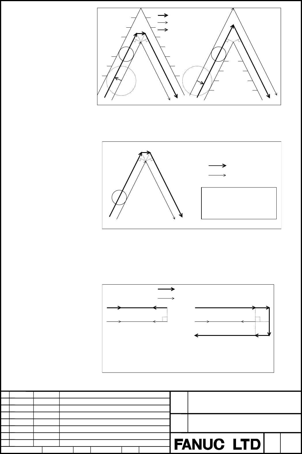
: Tool center path
: Programmed tool path
Example(1)-3
Example(1)-4
A
ctual tool
Reference tool
A
ctual tool
Reference tool
Workpiece
Workpiece
: Tool offcet value
Fig. 2.17.3 (e) Operation in the compensation mode (1)-3, 4
(2) When the tool moves at a corner, the feedrate of the previous block is used if
the corner is positioned before a single-block stop point; if the corner is after
a single-block stop point, the feedrate of the next block is used.
: Tool center path
: Programmed path
Example(2)-1
F100
Tool
Program(2)-1
:
N1 G90 G41.2 Xp Yp Zp Bp Cp D1 ;
N2 G01 Xq Yq Zq F100 ;
N3 Xr Yr Zr F200 ;
:
N2
N3
P'
P
Q1'
R'
R
Q
Q2' (Single block stop point)
Fig. 2.17.3 (f) Operation in the compensation mode (2)
In the above example, the single block stop point of N2 is Q2', so that the
feedrates along paths P'-Q1' and Q1'-Q2' are the same, namely, F100.
(3) When a command is specified to make the tool retrace the path specified in
the previous block, the tool path can match the locus of the previous block by
changing the G code to change the offset direction. If the G code is left
unchanged, the operation shown in Example (3)-2 results :
: Tool center path
: Programmed tool path
Example(3)-1 Tool movement when
changing G41.2 to G42.2
(G41.2 mode)
G91 G01 X100.0
G42.2 X-100.0
Example(3)-2 Tool movement when the
G code is left unchanged
(G41.2 mode)
G91 G01 X100.0
X-100.0
Fig. 2.17.3 (g) Operation in the compensation mode (3)
Contents Summary of FANUC Series 16i /18i Additional Manual
- Page 1FANUC Series 16i /18i –TB Specifications of AI High–precision Contour Control / AI Nano High–precision Contour Control FANUC Series 16i /18i -TB Title Specifications of AI High-Precision Contour Control / AI Nano High-Precision Contour control Draw 04 Feb.08.’03 Part of (4) is added or modified. Add
- Page 2Contents 1 Outline .................................................................................................................................6 1.1 Outline....................................................................................................................................6 2 Ope
- Page 32.15 Scaling, Coordinate System Rotation, Programmable Mirror Image...................................27 2.15.1 Scaling ..................................................................................................................27 2.15.2 Coordinate System Rotation .............................
- Page 42.24 Optimum Torque Acceleration/Deceleration......................................................................118 2.24.1 Outline .................................................................................................................118 2.24.2 Description ..............................
- Page 57 The Table of Function Available in the AI HPCC / AI NANO HPCC.................................188 AI Nano high precision contour control is the same as AI high precision contour control excluding being able to use the NANO interpolation. FANUC Series 16i /18i -TB Title Specifications of AI High-Pr
- Page 61 Outline 1.1 Outline This function is designed to achieve high-speed, high-precision milling machining with the complex lathe. This function can reduce the lag of the servo system and due to acceleration/deceleration that grows as speed is got up. Therefore, this function can be used to ensure that
- Page 72 Operation 2.1 Format The AI High Precision / AI Nano High Precision Contour Control mode can be turned on or off by the following commands. The character of "AI HPCC" is blinking displayed under the right of the screen in the AI High Precision Contour Control mode. " NANO HP" is displayed in the A
- Page 82.4 G Code System G code system in the AI HPCC / AI NANO HPCC mode becomes one for the machining center. To distinguish from normal G codes, the G code of the group, which can be commanded only in the AI HPCC / AI NANO HPCC mode, is displayed in reverse as the following figure. Reverse display FANUC
- Page 92.5 Absolute and Incremental Command In G code system A, the absolute or the incremental of the commanded value depends on G90/G91 displayed in reverse. Even if the AI HPCC / AI NANO HPCC mode is turns off and on, this modal data is kept. Example) N1 G00 X100. Z100. ; Absolute non-AI HPCC N2 G98 non
- Page 102.6 Diameter Programming and Radius Programming By the setting of the parameter No.8414#0(RRD), the command in the HPCC / AI NANO HPCC mode can be assumed to be radius programming even if the machine specification is diameter programming. • Manual operation The motion of the manual operation in the
- Page 11• Example • X axis : Diameter programming • Parameter 8414#0(RRD) = 1 G00 X0 Z0 ; N1 G00 X100. Z100. ; G05 P10000 ; N2 G90 X100. Z100. ; N3 X50. Z50. ; G05 P0 ; N4 X100.. Z100. ; X 100. (φ200.) ( ) : Diameter Value. N3 N2 N4 50. (φ100.) N1 Z O 50. 100. 2.7 Auxiliary Functions The auxiliary function
- Page 122.10 Tool Position Offset Tool position offset (T code) cannot be commanded in the AI HPCC / AI NANO HPCC mode. P/S alarm 5000 occurs when this is commanded. The tool position offset should be canceled before the AI HPCC / AI NANO HPCC mode is turned on. If not canceled, P/S alarm 5012 occurs. 2.11
- Page 132.11.3 Amount of Cutter Compensation In the cutter compensation C, the value of the tool nose radius is used as the value of the cutter compensation. Used as cutter radius offset amount The character of the cutter compensation number used in the AI HPCC / AI NANO HPCC mode is displayed in reverse as
- Page 142.11.6 Order of Command When G05 P10000 and G05 P0, and G41/G42 and G40 are to be specified together, G41/G42 and G40 must be nested between G05 P10000 and G05 P0. This means that AI HPCC / AI NANO HPCC mode cannot be started or canceled in cutter compensation (G41/G42) mode. If such a specification
- Page 152.11.7 Cancel When a block containing no movement operation is commanded together with the cutter compensation cancel code (G40), a vector with a length equal to the offset value is created in a direction perpendicular to the movement direction of the previous block. The cutter compensation mode is
- Page 162.12 Tool Length Compensation Tool length compensation can be used in the AI HPCC / AI NANO HPCC mode. The specification of the tool length compensation is similar to that of FANUC Series 16i-MB. Please refer to “FANUC Series 16i-MB OPERATORS MANUAL B-63534EN” for detail. 2.12.1 Format G05 P10000 ;
- Page 17The character of the tool length compensation number used in the AI HPCC / AI NANO HPCC mode is displayed in reverse as the following figure. Actual tool length compensation number 2.12.3 Target Axis The Z axis is the target of the tool length compensation. But it is possible to change the target ax
- Page 182.13 Smooth Interpolation 2.13.1 Outline Either of two types of machining can be selected, depending on the program command. (1) For those portions where the accuracy of the figure is critical, such as at corners, machining is performed exactly as specified by the program command. (2) For those port
- Page 19Table 2.13.3 (a) Profile Portions having mainly Portions having mainly a small radius of a large radius of curvature curvature Example of machined Automobile parts Decorative parts, such as parts body side moldings Length of line segment Short Long Resulting surfaces Smooth surface even Uneven surfa
- Page 20• Conditions for performing smooth interpolation Smooth interpolation is performed when all the following conditions are satisfied. If any of the following conditions is not satisfied for a block, that block is executed without smooth interpolation then the conditions are checked for the next block.
- Page 21• Modal G code of group 01 when instructing in G05.1 Q2 should be G01. When G code is not G01, P/S alarm 010 occurs. 2.13.5 Example Sample program of smooth interpolation G05 P10000 G05. 1 Q2 X0 Y0 Z0 N01 G91 G01 X1000 Z-300 F500 N02 X1000 Z-200 N03 X1000 Z-50 N04 X1000 Z50 N05 X1000 Z50 N06 X1000 Z
- Page 222.14 NURBS Interpolation 2.14.1 Outline This function enables NURBS (non-uniform rational B-spline) curve expression to be directly specified to the CNC. This eliminates the need for approximating the NURBS curve with minute line segments. This offers the following advantages: 1. No error due to app
- Page 232.14.2 Format G05 P10000 ; : Starting of AI HPCC / AI NANO HPCC mode G06.2 [P_] K_ X_ Y_ Z_ [R_] [F_] ; : Starting of NURBS interpolation mode K_ X_ Y_ Z_ [R_] ; K_ X_ Y_ Z_ [R_] ; K_ X_ Y_ Z_ [R_] ; ... K_ X_ Y_ Z_ [R_] ; K_ ; ... K_ ; G01 ... ; : Ending of NURBS interpolation mode G05 P0 ; : Endin
- Page 24• Weight The weight of a control point programmed in a single block can be defined. When the weight setting is omitted, a weight of 1.0 is assumed. • Knot The number of specified knots must equal the number of control points plus the rank value. In the blocks specifying the first to last control poi
- Page 252.14.4 Example G05 P10000; G90; ... G06.2 K0. X0. Z0.; K0. X300. Z100.; K0. X700. Z100.; K0. X1300. Z-100.; K0.5 X1700. Z-100.; K0.5 X2000. Z0.; K1.0; K1.0; K1.0; K1.0; G01 Y0.5; G06.2 K0. X2000. Z0.; K0. X1700. Z-100.; K0. X1300. Z-100.; K0. X700. Z100.; K0.5 X300. Z100.; K0.5 X0. Z0.; K1.0; K1.0;
- Page 262.14.5 NURBS curve Using these variables: k : Rank : Control point Pi : Weight wi x : Knot ( x ≤ x i i i +1 ) Knot vector [ ] (m = n + k ) x ,x 0 1 ,..., x m t : Spline parameter, The spline basis function N can be expressed with the de Boor-Cox recursive formula, as indicated below: ⎧⎪ 1 (x ≤ t ≤ x
- Page 272.15 Scaling, Coordinate System Rotation, Programmable Mirror Image 2.15.1 Scaling (1) All axis scaling • Outline A programmed figure can be magnified or reduced (scaling). To make this function effective, please set the parameter No.8485#0 (G51) and No.5401#0 (SCLx) to “1”. This function can use on
- Page 28(2) Each axis scaling • Outline Each axis can be scaled by different magnifications. To make this function effective, please set the parameter No.8485#0(G51), No.5401#0(SCLx), and No.5400#6(XSC) to “1”. This function can use only in the AI HPCC / AI NANO HPCC mode. This function is the additional op
- Page 29(3) Notes concerning scaling and each axis scaling • Scaling and each axis scaling Note When the each axis scaling is effective, all axis common magnification of P command cannot be used. Scaling is not executed by P command. • Instruction form Note Specify G50 and G51 in a separate block. Please ca
- Page 30• Circular interpolation Note Even if different magnifications are applied to each axis in circular interpolation, the tool will not trace an ellipse. Example ) G90 G00 X0.0 Y100.0 Z0.0 ; G51 X0.0 Y0.0 Z0.0 I2000 J1000; G02 X100.0 Y0.0 I0 J-100.0 F500 ; Above commands are equivalent to the following
- Page 31• Coordinate system rotation Note When both scaling and coordinate system rotation are specified, the coordinate system is rotated after scaling is applied. In this case, scaling is effective for the center of rotation. Example) O0001 ; G90 G00 X20. Y10. ; G05 P10000 ; G01 X50. F500 ; Y30. ; (a) X20
- Page 322.15.2 Coordinate System Rotation • Outline The coordinate system rotation is available in the AI HPCC / AI NANO HPCC mode. Only the coordinate system rotation in the AI HPCC / AI NANO HPCC mode is explained in the following descriptions. To make this function effective, please set the parameter No.
- Page 33• Plane The coordinate system rotation is executed on the selected plane (G17, G18, and G19) when G68 is commanded. The G code for selecting a plane (G17, G18, or G19) can be specified before the block containing the G code for coordinate system rotation (G68). • Cutter compensation C Cutter compens
- Page 34• Relationship with other functions Cutter compensation C It is possible to command G68 and G69 in the cutter compensation mode. The rotation plane must coincide with the plane of the cutter compensation. Example) N01 G01 G90 X0 Y0 ; N02 G42 X1000 Y1000 F1000 D01 ; N03 G68 R-30000 ; N04 G91 X2000 ;
- Page 35Y When only coordinate system rotation is applied When scaling and coordinate system rotation are applied When only scaling is applied Cutting program O X FANUC Series 16i /18i -TB Title Specifications of AI High-Precision Contour Control / AI Nano High-Precision Contour control Draw 04 Feb.08.’03 P
- Page 362.15.3 Programmable Mirror Image • Outline By a programmed command, the mirror image function can be used for each axis. The mirror image function selected by a CNC external switch or CNC setting is executed after the programmable mirror image function is executed. This function can use only in the
- Page 37Coordinate system rotation and scaling Note G50.1 and G51.1 must be specified in the G68 or G51 mode. (Example of an incorrect program (1)) G68 … ; G51.1…; … G50.1 …; G69 ; (Example of an incorrect program (2)) G51.1…; G68…; … G50.1…; G69 ; (Example of a correct program) G51.1…; G68…; … G69 ; G50.1…
- Page 38• Example If the contour of workpiece to be machined is symmetrical about an axis, use the programmable mirror image function and subprograms. The entire contour can be produced by programming a part of it. Y 100 N50 N30 60 50 N70 N90 O X 50 60 100 Subprogram Main program O9000 ; N10 G05 P10000 ; G0
- Page 392.15.4 Notes about Scaling, Coordinate System Rotation, and Programmable Mirror Image • Modal Note Please command the starting of AI HPCC / AI NANO HPCC (G05 P10000) in the state of G50(Scaling cancel), G69.1(Coordinate system rotation cancel), and G50.1(Programmable mirror image cancel). When the A
- Page 402.16 Tool Center Point Control for 5-axis Machining 2.16.1 Outline In this function, a rotary axis and a linear axis can be controlled so that a tool center point may move at programmed path and speed, in the compound machine with one rotary table axis and one tool head rotation axis. A tool center
- Page 412.16.2 Format G05 P10000 ; :Starting of AI HPCC / AI NANO HPCC mode G43.4 H_ ; :Starting tool center point control G01 X_ Z_ Y_ B_ C_ ; :Linear interpolation command ; including rotary axis command : : G49 ; :Ending of tool center point control G05 P0 ; :Ending of AI HPCC / AI NANO HPCC mode H code
- Page 42• When parameter No.19696#5(WKP) is ‘1’. X axis X axis C axis Y axis Y axis In setting where the programming coordinate system does not rotate, because the relation between workpiece and the programming coordinate system shifts by rotating workpiece, the programming by which it is considered is need
- Page 43• Operation of N3 when WKP of parameter No.19696#5 is ‘1’ X axis X axis X200. X200. C axis Y axis Y axis (3) Path of tool head Relative tool path of tool center point and workpiece It is controlled so that relative tool path of the tool center point and workpiece may become straight line when WKP of
- Page 44• Programmed point In programming, the position of the tool tip center is specified. It is necessary to pay attention to the programmed point in the machining by the tool such as the inclining flat end mill. Corner-radius-end mill Tool tip center Programmed path Flat-end mill Tool tip center Program
- Page 45• Tool length The length of a machine peculiar part from the tool pivot that is the center point of the tool rotary axis to the tool installation position is called the tool holder offset. The tool holder offset amount is set to the parameter No. 19666. It is individual from the tool length offset a
- Page 46• Spindle center compensation The gap of the spindle rotation centerline and the tool pivot can be corrected by setting the spindle center compensation vector in the parameter (No.19709— No.19711) when there is no pivot in the spindle rotation on center. Spindle rotation centerline Tool pivot (Contr
- Page 47• The actual position display in the tool center point control mode The position of tool pivot (control point) is displayed as the machine coordinate value. • The actual feedrate display in the tool center point control mode The feedrate of tool pivot (control point) is displayed as the actual feedr
- Page 48• Acceletation/deceletation before interpolation Please use the acceleration/deceleration before interpolation at the same time when you use tool center point control (Parameter No.19501#5(FRP)=1). When the acceleration/deceleration before interpolation is not used (Parameter (4) No.19501#5(FRP)=0),
- Page 49• Warning Warning 1. In the tool center point control mode, the following operations are done by commanding to rotary axes. (a) X, Z, and Y axis movement by table rotation. (b) X, Z, and Y axis movement by tool head rotation. The absolute coordinate system is shifted only by the movement of above- m
- Page 502.16.4 Example The each side of the equilateral triangle of 100mm in the length of about one is cut with B axis angle : -60 degree, -45 ∼ -30 degree, and –30 degree. The X axis is assumed to be a radius programming. < Program > The program example when the coordinate system fixed to the table is a p
- Page 51< Operation when assuming that C axis stationary and seeing from positive direction of Z > The following figure is showing of a relative position and the posture of work and the tool head seen from the direction of +Z. X and Y coordinates value in (3) figure are the values in the programming coordin
- Page 52< Decomposed figure > Path of control point (Machine coordinate system) B-90. [Until N031] [N032] B-45. B-60. X B-60. B Path of tool center point Y C120. Y X B-30. [N033] B-30. [N034] Apparent path of tool B-30. head Relative path of workpiece and head (3) C180. C240. Y B-45. X Y X [N035] [N041—] B-
- Page 532.16.5 Concerning Circular Interpolation and Helical Interpolation during Tool Center Point Control for 5-axis Machining • Circular Interpolation Format G05 P10000 ; Starting AI/AI nano contour control G43.4 IP H ; Starting the tool center point control for 5-axis machining G02 I_ J_ K_ G17 IP_ α_ β
- Page 54• Herical Interpolation Format G05 P10000 ; Starting AI/AI nano contour control G43.4 IP H ; Starting the tool center point control for 5-axis machining G02 I_ J_ K_ G17 IP α_ β_ γ_ F_ ; G03 R_ G02 I_ J_ K_ G18 IP α_ β_ γ_ F_ ; G03 R_ G02 I_ J_ K_ G19 IP α_ β_ γ_ F_ ; G03 R_ G49; Ending AI/AI nano c
- Page 55The velocity command can be given with two ways according to the setting of the parameter No. 1407#4 (RHT) as the following table. RHT(No..1407#4) 0 1 Tangent Speed of the arc Synthetic speed of the linear axis and tangent speed of the arc CNC interpolates including the rotary axis and controls the
- Page 56• Attention about Circular Interpolation and Helical Interpolation • The end point, start point, and center point of the arc moves according to the rotation of the rotary axis. • As for I, J, and K, the vector from the start point to the center point of the arc is specified. The then rotary axis pos
- Page 57In case of commanding G18 (Z-X plane) or G19 (Y-Z plane) − After commanding G43.4, Z-X plane is chosen by G18 command or Y-Z plane is chosen by G19 command, and the circular interpolation is performed while C axis is not rotated. ( Including the case of C axis moving before commanding G43.4 ) → The
- Page 58• Example of Circular Interpolation under Tool Center Point Control for 5-axis Machining As for the workpiece like a regular triangle that has a side of 100mm, linear interpolation is performed along a side of it and circular interpolation is performed along other two sides. When machining on each s
- Page 59< Example of Machine Configuration > The center of the B axis rotation The center of the C axis rotation Tool Center Point control X B axis C axis Z G54 : Y Workpiece coordinate system X axis Z axis Y axis FANUC Series 16i /18i -TB Title Specifications of AI High-Precision Contour Control / AI Nano
- Page 60The following figure shows the relative position and the posture of the workpiece and the tool seen from the direction of +Z. The coordinate values of X and Y in the figure is ones in the programming coordinate system fixed to the table. (This coordinate system is rotated according to rotation of C-
- Page 61[To N031] Movement of the control point [N032] B-45. B-90. B-60. X B-60. Y Movement on the tool center point C90. Y X Path of the head in appearance B-30. B-30. [N033] B-30. [N034] Relative path between the head and workpiece C150 Y C210 B-45. Y X X Path of the head Path of the head in appearance in
- Page 622.17 Tool Radius Compensation for 5-axis Machining 2.17.1 Outline B axis pivot X axis Tool center point C axis Z axis B axis Y axis C axis rotation center Fig. 2.17.1 Example of machine configuration This function allows three-dimensional tool radius compensation to be performed on a 5-axis machine
- Page 632.17.2 Format G05 P10000 ; : Starting of AI HPCC / AI NANO HPCC mode G41.5 (or G42.5) IP_D_ ; : Cutter compensation start : : G40 IP_ ; : Cutter compensation end G05 P0 ; : Ending of AI HPCC / AI NANO HPCC mode Each code has the following meaning. G41.5 : Cutter compensation, left (group 07) G42.5 :
- Page 642.17.3 Description • Start-up In offset cancel mode, issuing a command of tool radius compensation for 5-axsi machining (G41.5 or G42.5 with a D code other than D0) causes the CNC to enter offset mode. Startup may be specified with positioning (G00) or linear interpolation (G01). If, during startup,
- Page 65(2) Type B (Parameter No.5003#0(SUP)=1) Type B operation is similar to cutter compensation as shown below. Operation in linear interpolation :Tool center path :Programmed tool path Tool G40 G41.2 Operation in circular interpolation :Tool center path :Programmed tool path G40 G42.2 Tool Fig. 2.17.3 (
- Page 66(3) To the movement of the next block for the vertical direction (Parameter No.5003#1(SUV)=1) As shown in the following figures, when G41.2, G42.2, or G40 is specified, a block is inserted which moves the tool perpendicularly to the movement direction specified in the next block by the distance of t
- Page 67• Offset mode In offset mode, positioning (G00) and linear interpolation (G01) are subject to compensation. Note If, in G41.5 or G42.5 mode, a G code other than G00 and G01, such as circular interpolation (G02 or G03) is issued, compensation will not be performed properly. • Operation in the compens
- Page 68: Tool center path Workpiece : Programmed tool path : Tool offcet value Actual tool Actual tool Reference tool Workpiece Reference tool Example(1)-3 Example(1)-4 Fig. 2.17.3 (e) Operation in the compensation mode (1)-3, 4 (2) When the tool moves at a corner, the feedrate of the previous block is use
- Page 69• Formulas The three-dimensional cutter compensation vector at the N2 end point in the following program can be calculated as follows: 1. Part program A part program may be created with a workpiece coordinate system. G42.5 D1; N1 X x1 Y y1 Z z1 A a1 C c1 ; N2 X x2 Y y 2 Z z 2 A a2 C c 2 ; N3 X x3 Y
- Page 704. Conversion of program coordinates using the table rotation axis (1) Conversion from the workpiece coordinate system to the table coordinate system using the table rotation axis The table coordinate system is the one that is fixed to the table. The table coordinate system will move with the rotati
- Page 715. Calculation of three-dimensional cutter compensation (1) Conversion matrix for the tool rotation axis Conversion due to the rotation of the tool rotation axis about the tool axis having an angle of α (parameter No.19614) is represented by the following formula: ⎡ 1 − (sin 2 α )(1 − cos a ) (cos α
- Page 72e3 Q’ R'' e1=VT VD P’ e3 e2 VD' R’ P'' Z Q'' e2 Y X Coordinate system C1 Coordinate system C2 (4) Coordinate system conversion matrix for conversion from coordinate system C1 to coordinate system C2 The coordinate system conversion matrix for conversion from coordinate system C1 to coordinate system
- Page 73• Calculation used when the compensation plane is changed (1) When a rotation axis and linear axis are specified at the same time When a rotation axis and linear axis are specified in the same block in the G41.2 or G42.2 mode (the compensation plane changes frequently), the cutter compensation vecto
- Page 74(2) When a rotation axis is specified alone When a rotation axis is specified alone in the G41.2 or G42.2 mode (the compensation plane changes), the cutter compensation vector is calculated as follows :
G90 G00 X0 Y0 Z0 B0 C0 ; G01 F1000 ; N1 G42.2 Xp Yp Zp D1 ; N2 Xq Yq Zq ; N3 Br Cr ; N4 - Page 75Z Y N3 X N10 N7 N4 N6 N8 N9 N5 Fig. 2.17.3 (j) Conceptual Diagram Z C A Vb Va 45° 46° B Y Va: Tool direction vector when A = -46 Vb: Tool direction vector when A=45 A: End point of N3 B: End point of N4 C: End point of N6 Fig. 2.17.3 (k) Tool Direction Vector e3 e2 V2 B’ C’ A’ V1 A’ : Point A projec
- Page 76The move direction of A'B' is opposite to that of B'C', so that two compensation vectors, V1 and V2, are produced at point B' (end point of N4). There is a possibility of overcutting in this case, so an alarm (P/S41) is issued from N4. Conditions for issuing the interference alarm Suppose that the t
- Page 77When all the following conditions are satisfied, an alarm (P/S41) Issued. (1) The tool direction vector changes remarkably. α : Angle for determination set in parameter No.19633 (The default is 45°.) (Va,Vb) ≤ cos(α)(Here, (Va,Vb) means an inner product.) (2) The difference between the directions of
- Page 782.17.4 Parameter specification example When specifying the parameters related to a machine configuration, see the table below. For the machine shown in Fig.2.17.1, set the parameters to the settings listed in the table. Axis numbers is supposed to be as follows: X = 1, Z = 2, C = 3, Y = 4, and B = 5
- Page 792.17.5 Restrictions • Interference check In the Tool radius compensation for 5-axis machining mode, an interference check is performed using a specified position in the workpiece coordinate system and a compensation vector. • Corner arc (G39) In the Tool radius compensation for 5-axis machining mode
- Page 802.18 Three-dimensional Circular Interpolation 2.18.1 Outline Specifying an intermediate and end point on an arc enables circular interpolation in a 3-dimensional space. This function is an additional option. 2.18.2 Format G05 P10000 ; : Starting of AI HPCC / AI NANO HPCC mode G02.4 XX1 YY1 ZZ1 αα1 β
- Page 81• Movement along axes other than the 3-dimensional circular interpolation axis In addition to the 3-dimensional circular interpolation axis (X/Y/Z), up to two arbitrary axes ( α / β ) can be specified at a time. If α / β are omitted from the first block (mid-point specification) and are specified on
- Page 82• Whole circles A whole circle (360degree of an arc) cannot be specified. (This corresponds to the case in which linear interpolation is performed, as described earlier.) • Compensation functions Before using this function, cancel the compensation functions of group 07, such as cutter radius compens
- Page 832.19 Spiral Interpolation, Conical Interpolation 2.19.1 Outline Spiral interpolation can be executed when the circular interpolation command is specified together with the number of circles of the helix or a radius increment or decrement per circle. Conical interpolation can be executed when the spi
- Page 84• Conical interpolation Xp-Yp plane G02 G17 X_ Y_ I_ J_ Z_ Q_ L_ F_ ; G03 Zp-Yp plane G02 G18 Z_ X_ K_ I_ Y_ Q_ L_ F_ ; G03 Yp-Zp plane G02 G19 Y_ Z_ J_ K_ X_ Q_ L_ F_ ; G03 X,Y,Z : Position of the end point L : Number of circles (positive integer value) (*1) Q : Radius increment or decrement per ci
- Page 852.19.3 Description • Spiral interpolation functions Spiral interpolation in the XY plane is defined as follows. (X-X0)2+(Y-Y0)2=(R+Q')2 X0 : X coordinate of the center Y0 : Y coordinate of the center R : Initial radius in spiral interpolation Q' : Radius increment or decrement The above equation can
- Page 86Y 100.0 X -30.0 α -33.5 20.0 20.0 20.0 Q-20. G90 G02 X0 Y-33.5 I0 J-100. F300 ; L4 When the specified end point is (0,-33.5), the calculated end point is (0,-30.0). Specify a value greater than the difference ( α : permissible error) in parameter. Also set the parameter in this way, for the differen
- Page 87• Actual feedrate In spiral interpolation and conical interpolation, the feedrate is usually kept constant. When the radius of a spiral becomes small near the center of the spiral, however, the corresponding angular velocity may become very high. To prevent this from occurring, the system keeps the
- Page 882.19.5 Example • Spiral interpolation The path indicated above is programmed with absolute and incremental values, as shown below: 20. 20. 120 Y axis 100 80 60 40 20 -120 -100 -80 -60 -40 –20 20 40 60 80 100 120 -20 -40 X axis -60 -80 -100 -120 Fig.2.19.5 (a) Spiral interpolation This sample path ha
- Page 89• Conical interpolation +Z 25.0 25.0 (0,-37.5,62.5) 25.0 25.0 +Y 100.0 -100.0 +X Fig. 2.19.5 (b) Conical interpolation The sample path shown above is programmed with absolute and incremental values as follows: This sample path has the following values: - Start point : (0,100.0,0) - End point (X,Y) :
- Page 902.20 Helical Interpolation B 2.20.1 Outline Helical interpolation B allows the tool to move in helically. This can be done by specifying the circular interpolation command together with up to four axes. This function is an additional option. 2.20.2 Format Synchronously with arc of XpYp plane G02 I_
- Page 912.21 Cutting Point Compensation for Cylindrical Interpolation 2.21.1 Outline The conventional cylindrical interpolation function controls the tool center so that the tool axis always moves along a specified path on the cylindrical surface, towards the rotation axis (cylindrical axis) of the workpiec
- Page 922.21.2 Format G05 P10000 ; Sets AI HPCC / AI NANO HPCC mode. : G07.1 IPr ; Sets cylindrical interpolation mode. : ..G41(G42).. Sets cutter compensation mode. : ..G40.. Clear cutter compensation mode. : G07.1 IP0 ; Clears cylindrical interpolation mode. G05 P0 ; Clears AI HPCC / AI NANO HPCC mode. IP
- Page 93(2) Cutting point compensation in a circular command block As shown in Fig.2.21.3 (b), the movement required for cutting point compensation is made simultaneously with circular interpolation in block N1. 1) Let C0 be the head of the vector normal to N1 from S0, which is the tool center position at t
- Page 94(3) When cutting point compensation is not applied between blocks When, as shown in Fig.2.21.3 (c) and Fig.2.21.3 (d), the cutting point compensation value (V in the figures) is less than the value set in parameter No.19534, one of the operations below is performed. (The operation that is performed
- Page 952) When bit 6 (CYS) of parameter No. 19530 is set to 0 Cutting point compensation is not performed between blocks N1 and N2. Whether to apply cutting point compensation between block N2 and N3 is determined by taking the cutting point compensation value between blocks N2 and N3 (V1 in the figure) in
- Page 963) When the amount of travel (L1) of block N2 is less than the value set in parameter No. 19535, as shown in Fig.2.21.3 (e), cutting point compensation is not applied between blocks N1 and N2. Instead, block N2 is executed with the cutting point compensation of the previous block. When the amount of
- Page 974) When, as shown in Fig.2.21.3 (f) the diameter of an arc (R in the figure) is less than the value set in parameter No. 19535, cutting point compensation is not applied simultaneously with circular interpolation V : Cutting point compensation between blocks N2 and N3 C1 : Cutting surface of blocks
- Page 98• Feedrate during cutting point compensation (1) The tool moves at a specified feedrate while cutting point compensation is being applied between blocks. (2) The actual speed indication and feedrate during circular interpolation are as described below. Actual speed indication The speed component of
- Page 99• Usable G codes (1) In any of the following G code modes, cylindrical interpolation cutting point compensation can be specified: G01,G02 ,G03 : Linear interpolation, circular interpolation G17,G18,G19 : Plane selection G22 : Stored stroke check function on G90,G91 : Absolute command programming, in
- Page 1002.21.5 Example • Example of cylindrical interpolation cutting point compensation The sample program below indicates the positional relationships between a workpiece and tool. O0001(CYLINDRICAL INTERPOLATION1) ; N01 G00 G90 Z100.0 C0 ; N02 G01 G91 G19 Z0 C0 ; N03 G07.1 C57299 ; N04 G01 G42 G90 Z120.0
- Page 101Positional relationship between the Positional relationship between the workpiece and tool of (1) workpiece and tool of (2) Rotation Rotation Workpiece 0° 0° 20° Y-axis Cutting surface Y-axis Tool Tool center Positional relationship between the Positional relationship between the workpiece and tool
- Page 1022.22 Look-ahead Acceleration/Deceleration before Interpolation 2.22.1 General • Acceleration/Deceleration type There are two types of acceleration/deceleration, the linear acceleration/deceleration type and the bell-shaped acceleration/deceleration type. When bit 7(BDO) and bit 1(NBL) of parameter N
- Page 103• Example of deceleration To ensure that the feedrate specified for a block is reached when the block is executed, deceleration is started in the previous block. Feedrate Specified feedrate F3 P1 Feedrate after acceleration/ deceleration before interpolation is applied F2 P2 F1 Time N1 N2 To reduce
- Page 1042.22.2 Description (1) Setting an acceleration A permissible acceleration of each axis is set to the parameter 19510 and 8400. When the bell-shaped acceleration/deceleration is used, acceleration change time (B) (period of transition from constant speed state (A) to constant acceleration/deceleratio
- Page 105(2) Method of determining the tangent acceleration Acceleration/deceleration is performed with the largest tangent acceleration/deceleration that does not exceed the acceleration set for each axis. (Example) X-axis permissible acceleration: 1000 mm/sec2 Y-axis permissible acceleration: 1200 mm/sec2
- Page 106(3) Acceleration Acceleration is performed so that the feedrate programmed for a block is attained at the beginning of the block. Feedrate Speed control by bell-shaped acceleration/deceleration before interpolation Programmed speed Time N1 N2 N3 N4 N5 (4) Deceleration Deceleration starts in advance
- Page 107(5) Deceleration based on a distance If the total distance of the blocks read ahead becomes shorter than or equal to the deceleration distance obtained from the current feedrate, deceleration starts. If the total distance of the blocks read ahead during deceleration increases, acceleration is perfor
- Page 108(b) If A + B > Remaining amount of travel in the block being executed when the single-block command is executed A stop state may continue over several blocks. The stop is made as described later. Feedrate Single-block command Stop state continuing over multiple blocks A B Time A : Amount of travel t
- Page 109(b) If A > Remaining amount of travel in the block being executed when the single-block command is executed A stop state may continue over several blocks. The stop is made as described later. Feedrate Single-block command Stop state continuing over multiple blocks A Time A : Amount of travel corresp
- Page 1102.23 Automatic Feedrate Control Function 2.23.1 Outline This function reads several tens of blocks ahead to exercise automatic feedrate control in AI HPCC / AI NANO HPCC mode. A feedrate is determined on the basis of the conditions listed below. If a specified feedrate exceeds a calculated feedrate,
- Page 111• Feedrate control conditions In automatic feedrate control mode, the feedrate for the tool is controlled as described below. (a) The feedrate required at a corner is calculated from the specified feedrate difference at the corner along each axis, the tool being decelerated to the calculated feedrat
- Page 1122.23.2 Deceleration Based on the Feedrate Difference at a Corner With look-ahead acceleration/deceleration before interpolation, the tangent feedrate is changed smoothly. Thus, no path error occurs due to acceleration/deceleration delay. With this acceleration/declaration, however, acceleration/dece
- Page 113The method of deceleration based on the feedrate difference differs depending on the setting made for parameter FNW (bit 6 of No. 19500). If "0" is set, the largest feedrate that does not exceed the permissible feedrate difference set for parameter No. 8410 is assumed to be the deceleration feedrate
- Page 1142.23.3 Deceleration Based on the Acceleration along Each Axis As shown below, when a curve is formed by very short successive line segments, there is no significant feedrate difference along each axis at each corner. Consequently, the tool need not be decelerated to compensate for feedrate differenc
- Page 115The method of determining the feedrate with the acceleration differs depending on the setting of parameter FNW (bit 6 of No. 19500). If "0" is set, the highest feedrate that does not cause the permissible acceleration set for parameter No. 8470 to be exceeded is assumed to be the deceleration feedra
- Page 1162.23.4 Feedrate Determination Based on Cutting Load This function can be used when bit 4 (ZAG) of parameter No. 8451 is set to 1. θ Fig. 2.23.5 (a) When the tool is moving up Fig. 2.23.5 (b) When the tool is moving along the Z–axis down along the Z–axis Cutting the workpiece with the end of the cutt
- Page 117Note 1. Mounting direction of the tool should be parallel to Z axis to use this function. Therefore, this function might not be able to be applied according to the structure of the machine. 2. The feedrate determination function that is based on cutting load uses an NC command to determine the direc
- Page 1182.24 Optimum Torque Acceleration/Deceleration 2.24.1 Outline This function is an additional option. This function enables acceleration/deceleration in accordance with the torque characteristics of the motor and the characteristics of the machines due to its friction and gravity and performs linear t
- Page 1192.24.2 Description Optimum torque acceleration/deceleration selects the acceleration pattern set with parameters on the basis of the axial movement direction and the acceleration/deceleration state, determines the acceleration for each axis from the current speed, and controls the tangential acceler
- Page 120• Cases in which optimum torque acceleration/deceleration is disabled In case that optimum torque acceleration/deceleration is disabled, acceleration/deceleration for rapid traverse will be after-interpolation acceleration/deceleration or before interpolation acceleration/deceleration. When the comm
- Page 121For example, while the speed is between Fa and Fb in the previous figure, the acceleration is calculated with Aa and Ab. Tangential acceleration is controlled not to exceed the calculated acceleration for each axis Table. 2.24(b) Parameters for acceleration pattern Accelera Speed Acceleration parame
- Page 122• Example of setting acceleration pattern data In this example, the machine is equipped with the αM30/4000i. Motor speed at rapid traverse is 3000 (min-1). 150 Torque(Nm) 100 50 0 0 1000 2000 3000 4000 -1 Speed(min ) Fig. 2.24 (d) Speed-torque characteristics of model αM30/4000i Specifications of th
- Page 123Let the torque be x (Nm), the inertia be y(Kgm2), and the ball screw pitch p(mm), then the acceleration A is calculated as follows: x[ Nm] p x([kgm / sec2 ][m]) p A= × [ mm ] = × [mm] y[kgm 2 ] 2π y[kgm 2 ] 2π x× p = [mm / sec2 ] 2π × y Machine specification is assumed as follows, Ball screw pitch :
- Page 124Parameter Setting Unit Remarks No. Acceler 19546,19552 18712 0.01% At P1, 90(Nm) can be used for the ation at 19558,19564 acceleration/deceleration, so set the P1 ratio 7717 (mm/sec2) to 4124 (mm/sec2). 1.8712 = 7717/4124 Acceler 19547-19549 0 0.01% 0 is set because P2 to P4 are ation at 19553-19555
- Page 125• Examples of setting if the acceleration pattern differs depending on whether acceleration or deceleration is in progress and whether the movement is in the minus or plus direction From the effect of gravity and friction, torque for acceleration/deceleration is different on each condition, such as
- Page 126(1) In case of plus move (up) and acceleration Because torque of Gravity and friction work against the output torque of motor, the torque for acceleration/deceleration is as follows. Maximum torque : 70(=100-20-10) (Nm) Speed: 0 to 2000 (min-1) Torque at rapid traverse : 49(=79-20-10) (Nm) Speed: 30
- Page 127(2) In case of plus move (up) and deceleration Because torque of Gravity and friction work forward to the output torque of motor, the torque for acceleration/deceleration is as follows. Maximum torque : 130(=100+20+10) (Nm) Speed: 0 to 2000 (min-1) Torque at rapid traverse : 109(=79+20+10) (Nm) Spee
- Page 128(3) In case of minus move (down) and acceleration Because torque of Gravity works forward to the output torque of motor and torque of friction works against the output torque of motor, torque for acceleration/deceleration is as follows. Maximum torque : 110(=100+20-10) (Nm) Speed: 0 to 2000 (min-1)
- Page 129(4) In case of minus move (down) and deceleration Because torque of Gravity works against the output torque of motor and torque of friction works forward to the output torque of motor, torque for acceleration/deceleration is as follows. Maximum torque : 90(=100-20+10) (Nm) Speed: 0 to 2000 (min-1) T
- Page 1302.24.3 Limitations • Linear type positioning When Optimum torque acceleration/deceleration is enabled, linear type positioning for rapid traverse is selected automatically in AI HPCC / AI NANO HPCC mode even if the parameter LRP, bit 1 of parameter No. 1401, is set to 0 (nonlinear type is selected).
- Page 1312.25 Jerk Control 2.25.1 Outline To use this function, the rate of change of acceleration (jerk) will be smooth. As a result, vibration and shocks on the machine are reduced, leading to machining at higher precision. There are two types of jerk control functions as described below. <1> Speed control
- Page 1322.25.2 Speed control based on changes to acceleration for each axis • Outline Vibration or shocks may occur to the machine in portions where there is a large change to acceleration, for example, a portion where the shape specified by the machining program changes from a straight line to a curved lin
- Page 133• Setting a permissible acceleration change level Parameter No.19522 is used to set a permissible acceleration change level for each axis. The permissible acceleration change level is a rate per ms. If a parameter value is 0, speed control based on changes to acceleration is not performed for the ax
- Page 134• Continuous linear interpolation In speed control based on acceleration changes in continuous linear interpolation, the deceleration speed is obtained from changes to acceleration between the start and end points of a command block. When a machining program specifies a curved shape using continuous
- Page 1352.25.3 Look-ahead smooth bell-shaped acceleration/deceleration before interpolation Look-ahead bell-shaped acceleration/deceleration before interpolation achieves smooth acceleration/deceleration by making constant changes to acceleration in the specified acceleration change time. Look-ahead smooth
- Page 136• Setting jerk change time The jerk change time is set in parameter No.19524 as a ratio to the acceleration change time. Therefore, the actual jerk change time is determined as the ratio to the acceleration change time set in parameter No.8416. The jerk change time must be below or equal to half the
- Page 1373 Parameter 3.1 Introduction It is indispensable to set the following parameters to use AI HPCC / AI NANO HPCC function. Content Parameter number Reference item Control axes number 7510 3.2 Setting of RISC board 8485 3.2 Setting of 8402#5,#4 3.13 acceleration/deceleration before interpolation Settin
- Page 138G8S The advanced preview control for the serial spindle is: 0: Disabled. 1: Enabled. Please set this parameter to “1” in case of using Cs contour control in AI HPCC / AI NANO HPCC mode. FANUC Series 16i /18i -TB Title Specifications of AI High-Precision Contour Control / AI Nano High-Precision Conto
- Page 139#7 #6 #5 #4 #3 #2 #1 #0 8414 RRD [Data type] Bit RRD In the axis of the diameter programming, the program instruction in the AI HPCC / AI NANO HPCC mode is: 0: Radius programming 1: Diameter programming Note In setting this parameter to “1”, the moving amount in AI HPCC mode and AI NANO APCC mode is
- Page 1403.4 Cutter Compensation C #7 #6 #5 #4 #3 #2 #1 #0 5000 SBK [Data type] Bit SBK An internally created block for the cutter compensation C in AI HPCC / AI NANO HPCC mode: 0: Does not cause a single block stop. 1: Cause a single block stop. #7 #6 #5 #4 #3 #2 #1 #0 5003 BCK ICK SUV SUP [Data type] Bit S
- Page 1413.5 Tool Length Compensation #7 #6 #5 #4 #3 #2 #1 #0 5001 EVR TAL TLB TLC [Data type] Bit TLC Tool length compensation 0: Tool length compensation A or B (Conforms to parameter TLB) 1: Tool length compensation C. TLB Tool length compensation axis 0: Always Z axis irrespective of plane specification
- Page 1423.6 Helical Interpolation #7 #6 #5 #4 #3 #2 #1 #0 8485 G02 [Data type] Bit G02 In AI HPCC / AI NANO HPCC mode, the helical interpolation is: 0: Disabled. 1: Enabled. (Option is necessary) 3.7 Smooth Interpolation #7 #6 #5 #4 #3 #2 #1 #0 8485 CDS [Data type] Bit ICK In AI HPCC / AI NANO HPCC mode, th
- Page 1438490 Minimum travel distance of a block where smooth interpolation is applied [Data type] 2-word [Unit of data] Increment system IS-B IS-C Unit of data mm input 0.001 0.0001 Mm inch input 0.0001 0.00001 Inch [Valid data range] 0 to 99999999 This parameter specifies a block length used as a reference
- Page 1443.8 Scaling and Coordinate System Rotation #7 #6 #5 #4 #3 #2 #1 #0 8485 G51 [Data type] Bit G51 In AI HPCC / AI NANO HPCC mode, scaling and coordinate system rotation are: 0: Disabled. 1: Enabled. #7 #6 #5 #4 #3 #2 #1 #0 5400 SCR XSC RIN [Data type] Bit RIN Coordinate rotation angle command (R) 0: S
- Page 1455411 Magnification used when scaling magnification is not specified [Data type] 2-word [Unit of data] 0.001 or 0.00001 times (Selected using SCR, #7 of parameter No.5400) [Valid data range] 1 to 999999 This parameter sets the scaling magnification. This setting value is used when a scaling magnifica
- Page 1463.9 Tool Center Point Control for 5-axis Machining #7 #6 #5 #4 #3 #2 #1 #0 19501 FRP [Data type] Bit FRP A type of acceleration/deceleration of rapid traverse in AI HPCC / AI NANO HPCC mode is : 0: Acceleration/deceleration after interpolation. 1: Acceleration/deceleration before interpolation. Plea
- Page 147st 19681 Axis number of 1 rotary axis [Data type] Byte [Valid data range] 0 to Maximum controlled axis number Set the controlled axis number of 1st rotary axis. st 19682 The axis around which the 1 rotary axis rotates [Data type] Byte [Valid data range] 0 to 3 Set directions of axes of the 1st rotar
- Page 148st 19685 Angle of hypothetical axis (for 1 rotary axis) [Data type] 2-word [Unit of data] Increment system IS-B IS-C Unit Unit of data 0.001 0.0001 Deg [Valid data range] -99999999 to 99999999 When the 1st rotary axis is hypothetical axis (parameter No.19696#0(IA1)=1), set the angle of hypothetical
- Page 149#7 #6 #5 #4 #3 #2 #1 #0 19696 WKP IA2 IA1 [Data type] Bit IA1 A type of 1st rotary axis is: 0: Usual axis. 1: Hypothetical axis. When you set this parameter to 1, please set 0 to a parameter No.19681 which the axis number of rotary axis and set reasonable value to parameter No.19682—19685. IA2 A typ
- Page 15019700 Position of center of rotary table (X factor) 19701 Position of center of rotary table (Y factor) 19702 Position of center of rotary table (Z factor) [Data type] 2-word [Unit of data] Increment system IS-B IS-C Unit Millimeter 0.001 0.0001 mm machine Inch machine 0.0001 0.00001 inch [Valid dat
- Page 15119709 Spindle center compensation vector (X factor) 19710 Spindle center compensation vector (Y factor) 19711 Spindle center compensation vector (Z factor) [Data type] 2-word [Unit of data] Increment system IS-B IS-C Unit Millimeter 0.001 0.0001 Mm machine Inch machine 0.0001 0.00001 Inch [Valid dat
- Page 15219666 Tool holder offset [Data type] 2-word [Unit of data] Increment system IS-B IS-C Unit Millimeter 0.001 0.0001 Mm machine Inch machine 0.0001 0.00001 Inch [Valid data range] -99999999 to 99999999 Set the amount of the offset in a machine peculiar part from the rotation center of the rotary axis
- Page 153#7 #6 #5 #4 #3 #2 #1 #0 19609 CCT [Data type] Bit CCT Cancel command of G code of 08th group is : 0: Only G49 command. 1: G49 and G49.1 are available. Note When this parameter is set, the power must be turned off before operation is continued. 19718 Tool offset number of tool center point control (G
- Page 15419615 Rotation axis used to execute tool radius compensation for 5-axis machining (second set) 19616 Linear axis 1 used to execute tool radius compensation for 5-axis machining (second set) 19617 Linear axis 2 used to execute tool radius compensation for 5-axis machining (second set) 19618 Linear ax
- Page 155A) If the components of the direction vector of a rotation axis are in a single direction (type A) This is a case in which the rotation axis rotates about any one of the three basic axes. 1) Set the axis numbers for the rotation axis, linear axis 1, and linear axis 2. 2) Set 0 for the angle. 3) The
- Page 15619620 Reference angle of rotation axis used to execute tool radius compensation for 5-axis machining (first set) 19621 Reference angle of rotation axis used to execute tool radius compensation for 5-axis machining (second set) [Data type] 2 Word [Unit of data] increment system IS-B IS-C Unit Data un
- Page 157If the tool axis is in the direction of linear axis 1 Linear axis 3 RA = 0.0 Linear axis 2 RB = 90.0 Linear axis 1 • Parameters related to table rotation axes 19720 Axis number of linear axis 1 in the tool radius compensation for 5-axis machining 19721 Axis number of linear axis 2 in the tool radius
- Page 158Linear axis about which a Value set for parameter Rotation direction of the rotation axis Direction with an angular rotation axis rotates No.19724 or 19726 displacement of 0 Linear axis 1 Axis number of Forward direction of linear axis 2 to Forward direction of linear axis 1 forward direction of lin
- Page 1593.11 Spiral Interpolation, Conical Interpolation 3471 Permissible difference between the positions of the specified end point and the end point calculated from the increment or decrement and number of circles in spiral or conical interpolation [Data type] 2 Word [Unit of data] Increment system IS-B
- Page 1603.12 Cylindrical Interpolation Cutting Point Control #7 #6 #5 #4 #3 #2 #1 #0 19530 CYS CYA [Data type] Bit CYA Specifies whether to perform cylindrical interpolation cutting point compensation. 0: Perform. 1: Do not perform. CYS Specifies whether when the cylindrical interpolation cutting point comp
- Page 16119534 Limit for changing cylindrical interpolation cutting point compensation in a single block [Data type] 2 Word [Unit of data] mm, inch (input unit) [Valid data range] 1 - 999999999 The following operation is performed, depending on the setting of parameter No. 19530: 1) When CYS = 0 If the amoun
- Page 1623.13 Parameters of Look-ahead Acceleration and Deceleration before Interpolation #7 #6 #5 #4 #3 #2 #1 #0 1603 RSB [Data type] Bit RSB Set the type of acceleration/deceleration before interpolation. 0: Linear acceleration/deceleration. 1: Bell-shaped acceleration/deceleration. #7 #6 #5 #4 #3 #2 #1 #0
- Page 163Parameter 1 for determining an acceleration of acceleration/deceleration 8400 before interpolation [Data type] 2-word [Unit of data, Valid data range] Valid data range Increment system Unit of data IS-B IS-C Millimeter machine 1 mm/min 10∼60000 1∼6000 Inch machine 0.1 inch/min 10∼60000 1∼6000 Rotati
- Page 164The time required to the maximum acceleration in advanced preview bell– 8416 shaped acceleration/deceleration before interpolation [Data type] 2-word [Unit of data] 1ms [Valid data range] 0 to 200 The “tb” of the figure below is set in this parameter. It becomes a linear acc/deceleration before inte
- Page 1653.14 Automatic Feedrate Control Function #7 #6 #5 #4 #3 #2 #1 #0 8451 NOF ZAG USE [Data type] Bit USE Automatic velocity control is: 0 : Not applied. 1 : Applied. ZAG The velocity is: 0: Not determined according to the angle at which the machine descends along the Z–axis. 1: Determined according to
- Page 166#7 #6 #5 #4 #3 #2 #1 #0 8475 CIR BIP [Data type] Bit CIR The function of automatic feedrate control considering acceleration and deceleration during circular interpolation is: 0: Not used. 1: Used. When 1 is set, parameter No.8470 for determining the allowable acceleration must be specified. BIP The
- Page 167Parameter for determining allowable acceleration in feedrate calculation 8470 considering acceleration [Data type] Word axis [Unit of data] msec [Valid data range] 0 to 32767 When the function for calculating the feedrate considering the acceleration is used under automatic feedrate control, this pa
- Page 1688456 Area–2 override [Data type] Word [Unit of data] % [Valid data range] 0 to 100 (Standard setting: 80) This parameter specifies an override in area 2 of velocity calculation considering the cutting load. 8457 Area–3 override [Data type] Word [Unit of data] % [Valid data range] 0 to 100 (Standard
- Page 169Lower feedrate limit for the deceleration function based on the acceleration of 19511 AI HPCC / AI NANO HPCC [Data type] 2-word [Unit of data, Valid data range] Valid data range Increment system Unit of data IS-B IS-C Millimeter machine 1 mm/min 10∼240000 1∼100000 Inch machine 0.1 inch/min 10∼96000
- Page 1703.15 Optimum Torque Acceleration/Deceleration #7 #6 #5 #4 #3 #2 #1 #0 19540 FAP [Data type] Bit FAP Optimum torque acceleration/deceleration is: 0: Disabled. 1: Enabled. By setting both FAP, bit 0 of parameter No. 19540, and FRP, bit 5 of parameter No. 19501, to 1 and setting parameter to determine
- Page 1711420 Rapid traverse rate for each axis [Data type] Two-word axis [Unit of data, Valid data range] Valid data range Increment system Unit of data IS-B IS-C Millimeter machine 1 mm/min 30∼240000 6∼100000 Inch machine 0.1 inch/min 30∼96000 6∼48000 Rotation axis 1 deg/min 30∼240000 6∼100000 Set the rapi
- Page 172Time constant t T 2 for each axis used for bell–shaped acceleration / 1774 deceleration in rapid traverse of Optimum torque acceleration/deceleration [Data type] Word axis [Unit of data] msec [Valid data range] 0 to 512 Specify a time constant T2 for bell–shaped acceleration/deceleration in rapid tr
- Page 173Setting acceleration pattern data Acceleration Acceleration pattern P0 P1 P2 P3 P4 P5 Speed Set the speed and the acceleration at each of the acceleration setting points P0 to P5 for each condition, acceleration and + move, deceleration and + move, acceleration and – move , deceleration and – move.,
- Page 174Optimum torque acceleration/deceleration (acceleration at P0 during 19557 movement in + direction and deceleration) Optimum torque acceleration/deceleration (acceleration at P1 during 19558 movement in + direction and deceleration) Optimum torque acceleration/deceleration (acceleration at P2 during
- Page 1753.16 Jerk Control 19522 Permissible acceleration change level for each axis in speed control based on acceleration changes for jerk control [Data type] 2 Word axis [Unit of data] Increment system IS-B IS-C Unit Millimeter –machine 0.0001 0.001 mm / s 2 Inch-machine 0.0001 0.00001 2 inch / s Rotation
- Page 17619524 Ratio of the jerk change time in smooth bell-shaped acceleration/deceleration before interpolation [Data type] Byte [Unit of data] % [Valid data range] 0 to 50 Specify the percent jerk change time with respect to the acceleration change time (*1) in look-ahead smooth bell-shaped acceleration/
- Page 1773.17 Acceleration/deceleration after interpolation #7 #6 #5 #4 #3 #2 #1 #0 1602 LS2 BS2 [Data type] Bit LS2, BS2 Set the type of acceleration/deceleration after interpolation of AI HPCC / AI NANO HPCC mode. LS2 BS2 Meaning Acceleration/deceleration after interpolation is not 0 0 available. Lenear ac
- Page 1784 Signal HPCC mode signal MHPCC (F066#6) [Classification] Output signal [Function] Indicates that the system is set to AI HPCC / AI NANO HPCC mode. [Output condition] The signal is set to 1 if G05 P10000 (AI HPCC / AI NANO HPCC mode ON) is specified in a program. The signal is set to 0 if G05 P0 is
- Page 1795 Alarm and Message Number Message Description 10 IMPROPER G–CODE · There is no option of the corresponding function. · An unusable G code G is specified. · The following instructions are commanded in G00 mode. G50 / G51 (Scaling) G68 / G69 (Coordinate system rotation) G50.1 / G51.1 (Programmable mi
- Page 1805013 HPCC:CRC OFS REMAIN · G05 P0 was commanded with in the G41/G42 mode or AT CANCEL the amount of the offset remained. · G05 P0 was instructed in in G51.1 (programmable mirror image) mode. · G05 P0 was instructed in G43.4(tool center point control) modes. 5115 SPL:ERROR In the NURBS interpolation,
- Page 1815313 G05 P0 COMMANDED IN G05 P0 was commanded in the coordinate system G68.1/G51 rotation or in the scaling mode. 5314 SMOOTH IPL ERROR 1 The mistake is found in the format of smooth interpolation block. 5422 EXCESS VELOCITY IN The axis was about to move by tool center point control G43.4/G43.5 exce
- Page 1826 Notes 6.1 Relation between AI HPCC / AI NANO HPCC and Another Functions • Unavailable functions in AI HPCC mode The following functions cannot be used in AI HPCC / AI NANO HPCC mode. • Sequence Number Comparison and Stop It is not possible to stop by the sequence number in the AI HPCC / AI NANO HP
- Page 183• Workpiece coordinate system preset -G50.3 [G92.1] • Local coordinate system setting -G52 • Machine coordinate system setting -G53 • Single direction positioning -G60 • Automatic corner override -G62 • Cutting mode -G64 • Macro call -G65, G66, G67, G66.1 (The subprogram call is possible.) • Three d
- Page 1846.3 Notes on Programming • Programming sequence When you use following functions, they must be nested between G05 P10000 and G05 P0. • Coordinate system rotation (G68/G69) • Scaling(G50/ G51) • NURBS interpolation(G06.2) • Smooth interpolation(G05.1Q2) • Cutter compensation C • Tool length compensat
- Page 185Example 2 ) When the under-mentioned program is executed, the starting point of N5 is decided by the vector made with N3 and N4. N1 N2 N3 N4 N5 O0001 ; G50 X-10. Y-20. ; G05 P10000 ; N1 G01 G42 X0 D1 F1000 ; N6 N2 X20. ; N3 X40. Y0 ; N4 X60. Y20. ; This vector is used as the vector N5 M50 X80. ; bet
- Page 1866.5 Automatic Feedrate Control • Maximum feedrate If the upper limit for automatic feedrate control is set to 0 in parameter No. 8465, no feedrate exceeding 0 is permitted, such that the issue of an F command causes P/S alarm 011. To prevent this, specify a value other than zero in the parameter. •
- Page 1876.8 Rotary Axis • Rotary Axis Control Function The optional Rotary Axis Control Function is not available in AI HPCC / AI NANO HPCC mode. 6.9 Program Restart Function • Parameter setting Please set ‘1’ in MSU of parameter No.8403#1 when you use the program restart function to the program which conta
- Page 1887 The Table of Function Available in the AI HPCC / AI NANO HPCC The function excluding this cannot be used. Item Specifications Remarks Controlled axis Controlled axis 2 axes Controlled path 1 path Simultaneously controlled axes 2 axes Controlled axis expansion(total) Max. 8 axes Simultaneously cont
- Page 189Item Specifications Remarks Interpolation function Positioning G00 Linear interpolation G01 Circular interpolation G02,G03 Three-dimensional circular G02.4,G03.4 Option is necessary. interpolation Helical interpolation Circular interpolation plus max. 2 Option is necessary. axes linear interpolation
- Page 190Item Specifications Remarks Program input Tape code EIA/ISO automatic recognition Program format Word and address format Control in/out Optional block skip Absolute/incremental programming G90/G91 Input unit 10 time multiply Plane selection G17,G18,G19 Rotary axis roll-over Manual absolute on and of