FANUC POWER MATE 0 Operators manual Page 123
Operators manual
PROGRAMMING
B–63444EN/01
13. COMPENSATION FUNCTION
109
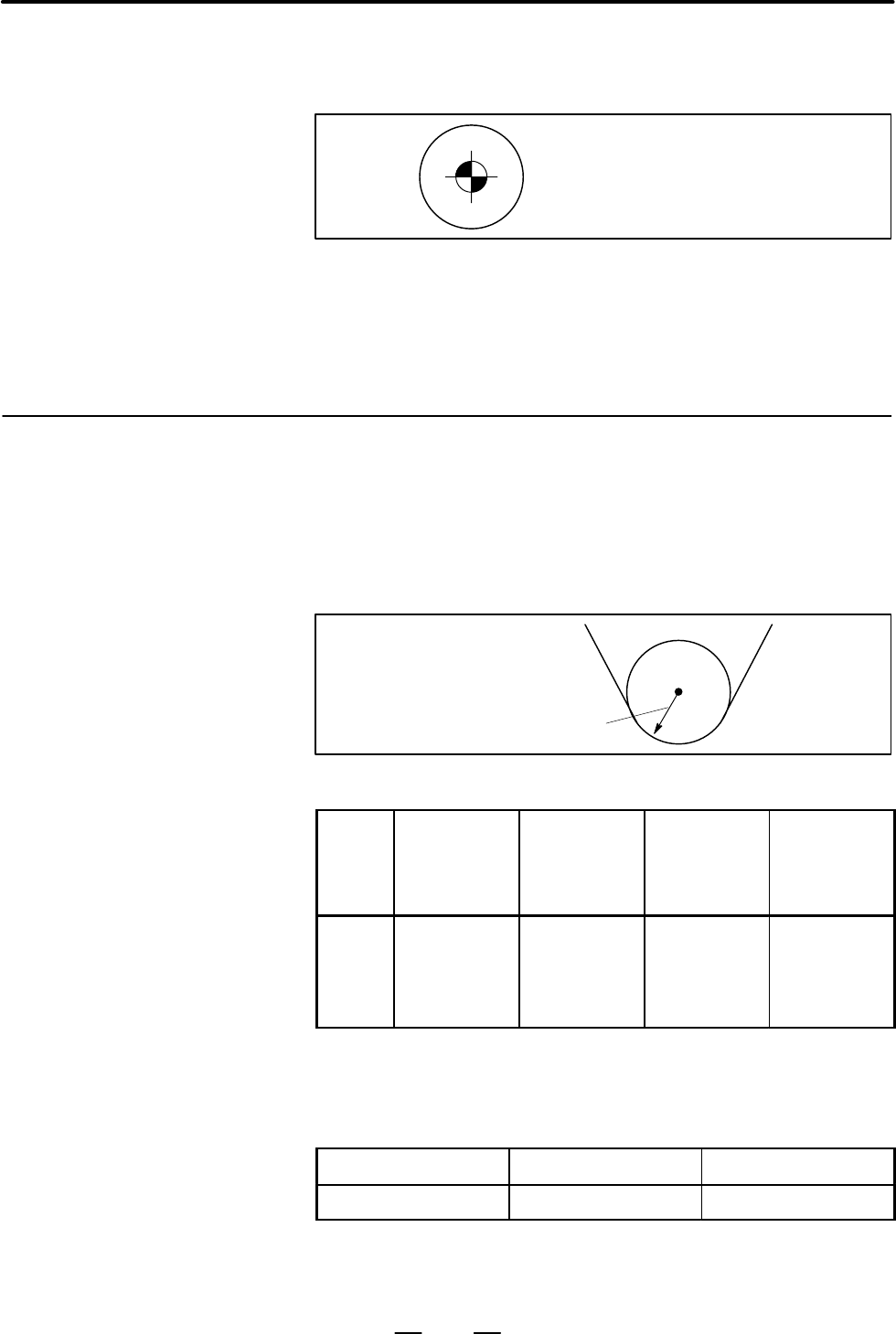
Imaginary tool nose numbers 0 and 9 are used when the tool nose center
coincides with the start position. Set imaginary tool nose number to
address OFT for each offset number.
Imaginary tool nose number 0 to 9
Virtual tool nose directions 1 to 8 can be used only in the G18 (Z–X) plane.
Tool nose radius compensation value
(Tool nose radius value)
Table 13.2.3 (a) Offset number and offset value
Offset
number
OFX
(Offset value
on X axis)
OFZ
(Offset value
on Z axis)
OFR
(Tool nose
radius
compensa-
tion value)
OFT
(Direction of
imaginary
tool nose)
01
02
:
15
16
0.040
0.060
:
0.050
0.030
0.020
0.030
:
0.015
0.025
0.20
0.25
:
0.12
0.24
1
2
:
6
3
A offset number is specified with the same T code as that used for tool
offset. For details, see Subsec. II–13.1.1.
The range of the offset value is an follows :
Increment system metric system Inch system
IS–B 0 to "999.999 mm 0 to "99.9999 inch
The offset value corresponding to the offset number 0 is always 0.
No offset value can be set to offset number 0.
Limitations
D Plane selection
13.2.3
Offset Number and
Offset Value
Explanations
D Offset number and offset
value
D Command of offset value
D Setting range of offset
value
Contents Summary of FANUC POWER MATE 0 Operators manual
- Page 1GE Fanuc Automation Europe Computer Numerical Controls Power Mate - 0 Operator’s Manual B-63444EN/01 TECHNOLOGY AND MORE
- Page 2
- Page 3SAFETY PRECAUTIONS This section describes the safety precautions related to the use of CNC units. It is essential that these precautions be observed by users to ensure the safe operation of machines equipped with a CNC unit (all descriptions in this section assume this configuration). Note that some
- Page 4SAFETY PRECAUTIONS B–63444EN/01 1 DEFINITION OF WARNING, CAUTION, AND NOTE This manual includes safety precautions for protecting the user and preventing damage to the machine. Precautions are classified into Warning and Caution according to their bearing on safety. Also, supplementary information i
- Page 5B–63444EN/01 SAFETY PRECAUTIONS 2 GENERAL WARNINGS AND CAUTIONS WARNING 1. Never attempt to machine a workpiece without first checking the operation of the machine. Before starting a production run, ensure that the machine is operating correctly by performing a trial run using, for example, the sing
- Page 6SAFETY PRECAUTIONS B–63444EN/01 WARNING 8. Some functions may have been implemented at the request of the machine–tool builder. When using such functions, refer to the manual supplied by the machine–tool builder for details of their use and any related cautions. NOTE Programs, parameters, and macro
- Page 7B–63444EN/01 SAFETY PRECAUTIONS 3 WARNINGS AND CAUTIONS RELATED TO PROGRAMMING This section covers the major safety precautions related to programming. Before attempting to perform programming, read the supplied operator’s manual and programming manual carefully such that you are fully familiar with
- Page 8SAFETY PRECAUTIONS B–63444EN/01 WARNING 6. Stroke check After switching on the power, perform a manual reference position return as required. Stroke check is not possible before manual reference position return is performed. Note that when stroke check is disabled, an alarm is not issued even if a s
- Page 9B–63444EN/01 SAFETY PRECAUTIONS 4 WARNINGS AND CAUTIONS RELATED TO HANDLING This section presents safety precautions related to the handling of machine tools. Before attempting to operate your machine, read the supplied operator’s manual and programming manual carefully, such that you are fully fami
- Page 10SAFETY PRECAUTIONS B–63444EN/01 WARNING 7. Workpiece coordinate system shift Manual intervention, machine lock, or mirror imaging may shift the workpiece coordinate system. Before attempting to operate the machine under the control of a program, confirm the coordinate system carefully. If the machin
- Page 11B–63444EN/01 Table of Contents SAFETY PRECAUTIONS . . . . . . . . . . . . . . . . . . . . . . . . . . . . . . . . . . . . . . . . . . s–1 I. GENERAL 1. GENERAL . . . . . . . . . . . . . . . . . . . . . . . . . . . . . . . . . . . . . . . . . . . . . . . . . . . . . . . . . . . . 3 1.1 GENERAL PROCED
- Page 12Table of Contents B–63444EN/01 5.4 DWELL (G04) . . . . . . . . . . . . . . . . . . . . . . . . . . . . . . . . . . . . . . . . . . . . . . . . . . . . . . . . . . . . . . . . . . 59 6. REFERENCE POSITION . . . . . . . . . . . . . . . . . . . . . . . . . . . . . . . . . . . . . . . . . . . . . . . .
- Page 13B–63444EN/01 Table of Contents 13.3.2 Tool Movement in Start–up . . . . . . . . . . . . . . . . . . . . . . . . . . . . . . . . . . . . . . . . . . . . . . . . . . . . . . . . . 118 13.3.3 Tool Movement in Offset Mode . . . . . . . . . . . . . . . . . . . . . . . . . . . . . . . . . . . . . . . . .
- Page 14Table of Contents B–63444EN/01 1.7.3 Alarm Display (See Section III–7.1) . . . . . . . . . . . . . . . . . . . . . . . . . . . . . . . . . . . . . . . . . . . . . . . . . . . 203 1.8 DATA OUTPUT . . . . . . . . . . . . . . . . . . . . . . . . . . . . . . . . . . . . . . . . . . . . . . . . . . . . .
- Page 15B–63444EN/01 Table of Contents 7.4 DISPLAYING AND SETTING PMC DATA IN DIAGNOSIS SCREEN (DPL/MDI) . . . . . . . . . . . 269 8. DATA INPUT/OUTPUT . . . . . . . . . . . . . . . . . . . . . . . . . . . . . . . . . . . . . . . . . . . . . . . . . . 272 8.1 FILES . . . . . . . . . . . . . . . . . . . . .
- Page 16Table of Contents B–63444EN/01 11.1.4 Actual Feedrate Display . . . . . . . . . . . . . . . . . . . . . . . . . . . . . . . . . . . . . . . . . . . . . . . . . . . . . . . . . . . . 336 11.2 SCREENS DISPLAYED BY FUNCTION KEY PROG (IN MEMORY MODE OR MDI MODE) . . . . . . . . . . . . . . . . . . . . .
- Page 17B–63444EN/01 Table of Contents D.4 RADIUS DIRECTION ERROR AT CIRCLE CUTTING . . . . . . . . . . . . . . . . . . . . . . . . . . . . . . . . . 398 E. STATUS WHEN TURNING POWER ON, WHEN CLEAR AND WHEN RESET . . . . . . . . . . . . . . . . . . . . . . . . . . . . . . . . . . . . . . . . . . . . . . . .
- Page 18I. GENERA
- Page 19B–63444EN/01 GENERAL 1. GENERAL 1 GENERAL This manual consists of the following parts: About this manual I. GENERAL Describes chapter organization, applicable models, related manuals, and notes for reading this manual. II. PROGRAMMING Describes each function: Format used to program functions in the
- Page 201. GENERAL GENERAL B–63444EN/01 Related manuals The table below lists manuals related to the FANUC Power Mate 0. In the table, this manual is marked with an asterisk (*). Table 1 Manuals Related to the FANUC Power Mate 0 Specification Manual name number FANUC Power Mate 0 OPERATOR’S MANUAL B–63444EN
- Page 21B–63444EN/01 GENERAL 1. GENERAL 1.1 When operating a machine equipped with an NC, you must first create a program then operate the machine according to that program. GENERAL PROCEDURE FOR 1) First, prepare the program from a operation plan to operate the NC machine tool. OPERATING How to prepare the
- Page 221. GENERAL GENERAL B–63444EN/01 Outer End diameter face Grooving cutting cutting Workpiece Prepare the program of the tool path and cutting condition according to the workpiece figure, for each process. 6
- Page 23B–63444EN/01 GENERAL 1. GENERAL 1.2 NOTES ON NOTE READING THIS 1 The function of a machine system depends not only on the MANUAL NC, but on the combination of the machine tool, its magnetic cabinet, the servo system, the NC, the operator’s panels, etc. It is too difficult to describe the function, p
- Page 24II. PROGRAMMIN
- Page 25B–63444EN/01 PROGRAMMING 1. GENERAL 1 GENERAL 11
- Page 261. GENERAL PROGRAMMING B–63444EN/01 1.1 The tool moves along straight lines and arcs constituting the workpiece parts figure (See II–4). TOOL MOVEMENT ALONG WORKPIECE PARTS FIGURE– INTERPOLATION Explanations D Tool movement along a straight line X Tool Program G01 Z...; Workpiece Z Fig.1.1 (a) Tool
- Page 27B–63444EN/01 PROGRAMMING 1. GENERAL The term interpolation refers to an operation in which the tool moves along a straight line or arc in the way described above. Symbols of the programmed commands G01, G02, ... are called the preparatory function and specify the type of interpolation conducted in t
- Page 281. GENERAL PROGRAMMING B–63444EN/01 X Tool Program G32X––Z––F––; Workpiece Z F Fig.1.1 (f) Taper thread cutting 14
- Page 29B–63444EN/01 PROGRAMMING 1. GENERAL 1.2 Movement of the tool at a specified speed for cutting a workpiece is called the feed. FEED–FEED FUNCTION Chuck Tool Workpiece Fig.1.2 (a) Feed function Feedrates can be specified by using actual numerics. For example, the following command can be used to feed
- Page 301. GENERAL PROGRAMMING B–63444EN/01 1.3 PART DRAWING AND TOOL MOVEMENT 1.3.1 A CNC machine tool is provided with a fixed position. Normally, tool Reference Position change and programming of absolute zero point as described later are performed at this position. This position is called the reference
- Page 31B–63444EN/01 PROGRAMMING 1. GENERAL 1.3.2 Coordinate System on Part Drawing and X X Coordinate System Specified by CNC – Program Coordinate System Z Z Coordinate system Part drawing CNC Command X Workpiece Z Machine tool Fig.1.3.2 (a) Coordinate system Explanations D Coordinate system The following
- Page 321. GENERAL PROGRAMMING B–63444EN/01 The tool moves on the coordinate system specified by the CNC in accordance with the command program generated with respect to the coordinate system on the part drawing, and cuts a workpiece into a shape on the drawing. Therefore, in order to correctly cut the work
- Page 33B–63444EN/01 PROGRAMMING 1. GENERAL 2. When coordinate zero point is set at work end face. X Workpiece 60 30 Z 30 80 100 Fig.1.3.2 (e) Coordinates and dimensions on part drawing X Workpiece Z Fig.1.3.2 (f) Coordinate system on lathe as specified by CNC (made to coincide with the coordinate system on
- Page 341. GENERAL PROGRAMMING B–63444EN/01 1.3.3 How to Indicate Command Dimensions for Moving the Tool – Absolute, Incremental Commands Explanations Methods of command for moving the tool can be indicated by absolute or incremental designation (See II–8.1). D Absolute command The tool moves to a point at
- Page 35B–63444EN/01 PROGRAMMING 1. GENERAL D Incremental command Specify the distance from the previous tool position to the next tool position. Tool A X φ60 B Z φ30 40 Command specifying movement from point A to point B U–30.0W–40.0 Distance and direction for movement along each axis Fig.1.3.3 (b) Increme
- Page 361. GENERAL PROGRAMMING B–63444EN/01 2. Radius programming In radius programming, specify the distance from the center of the workpiece, i.e. the radius value as the value of the X axis. X B A 20 15 Workpiece Z 60 80 Coordinate values of points A and B A(15.0, 80.0), B(20.0, 60.0) Fig.1.3.3 (d) Radiu
- Page 37B–63444EN/01 PROGRAMMING 1. GENERAL 1.4 The speed of the tool with respect to the workpiece when the workpiece is cut is called the cutting speed. CUTTING As for the CNC, the cutting speed can be specified by the spindle speed SPEED–SPINDLE in rpm unit. SPEED FUNCTION Tool V: Cutting speed v m/min W
- Page 381. GENERAL PROGRAMMING B–63444EN/01 1.5 When drilling, tapping, boring, milling or the like, is performed, it is necessary to select a suitable tool. When a number is assigned to each tool SELECTION OF TOOL and the number is specified in the program, the corresponding tool is USED FOR VARIOUS select
- Page 39B–63444EN/01 PROGRAMMING 1. GENERAL 1.6 When machining is actually started, it is necessary to rotate the spindle, and feed coolant. For this purpose, on–off operations of spindle motor and COMMAND FOR coolant valve should be controlled (See II–11). MACHINE OPERATIONS– Coolant on/off MISCELLANEOUS F
- Page 401. GENERAL PROGRAMMING B–63444EN/01 1.7 A group of commands given to the NC for operating the machine is called the program. By specifying the commands, the tool is moved along a PROGRAM straight line, or the spindle motor is turned on and off. CONFIGURATION In the program, specify the commands in t
- Page 41B–63444EN/01 PROGRAMMING 1. GENERAL Explanations The block and the program have the following configurations. D Block 1 block N ffff G ff X ff.f Z fff.f M ff S ff T ff ; Sequence Preparatory Dimension word Miscel- Spindle Tool number function laneous function func- function tion End of block Fig.1.7
- Page 421. GENERAL PROGRAMMING B–63444EN/01 D Main program and When machining of the same pattern appears at many portions of a subprogram program, a program for the pattern is created. This is called the subprogram. On the other hand, the original program is called the main program. When a subprogram execu
- Page 43B–63444EN/01 PROGRAMMING 1. GENERAL 1.8 TOOL FIGURE AND TOOL MOTION BY PROGRAM Explanations D Machining using the end Usually, several tools are used for machining one workpiece. The tools of cutter – Tool length have different tool length. It is very troublesome to change the program compensation f
- Page 441. GENERAL PROGRAMMING B–63444EN/01 1.9 Limit switches are installed at the ends of each axis on the machine to prevent tools from moving beyond the ends. The range in which tools can TOOL MOVEMENT move is called the stroke. Besides the stroke limits, data in memory can RANGE–STROKE be used to defin
- Page 45B–63444EN/01 PROGRAMMING 2. CONTROLLED AXES 2 CONTROLLED AXES 31
- Page 462. CONTROLLED AXES PROGRAMMING B–63444EN/01 2.1 CONTROLLED AXES No. of basic controlled axes 2 axes Basic simultaneously controlled axes 2 axes 2.2 The axis name must always be X or Z. Parameter No. 1020 is used to determine the name of each axis. AXIS NAME When this parameter is set to 0 or a chara
- Page 473. PREPARATORY FUNCTION B–63444EN/01 PROGRAMMING (G FUNCTION) 3 PREPARATORY FUNCTION (G FUNCTION) A number following address G determines the meaning of the command for the concerned block. G codes are divided into the following two types. Type Meaning One–shot G code The G code is effective only in
- Page 483. PREPARATORY FUNCTION (G FUNCTION) PROGRAMMING B–63444EN/01 Explanations 1. If the CNC enters the clear state (see bit 6 (CLR) of parameter 3402) when the power is turned on or the CNC is reset, the modal G codes change as follows. (1) G codes marked with in Table 3 are enabled. (2) When the syste
- Page 493. PREPARATORY FUNCTION B–63444EN/01 PROGRAMMING (G FUNCTION) Table 3 G code list G code Group Function A B C G00 G00 G00 Positioning (Rapid traverse) G01 G01 G01 Linear interpolation (Cutting feed) 01 G02 G02 G02 Circular interpolation CW G03 G03 G03 Circular interpolation CCW G04 G04 G04 Dwell G10
- Page 504. INTERPOLATION FUNCTIONS PROGRAMMING B–63444EN/01 4 INTERPOLATION FUNCTIONS 36
- Page 51B–63444EN/01 PROGRAMMING 4. INTERPOLATION FUNCTIONS 4.1 The G00 command moves a tool to the position in the workpiece system specified with an absolute or an incremental command at a rapid traverse POSITIONING (G00) rate. In the absolute command, coordinate value of the end point is programmed. In t
- Page 524. INTERPOLATION FUNCTIONS PROGRAMMING B–63444EN/01 Examples X 30.5 56.0 ÎÎÎ ÎÎÎ 30.0 ÎÎÎ Z φ40.0 < Radius programming > G00X40.0Z56.0 ; (Absolute command) or G00U–60.0W–30.5;(Incremental command) Restrictions The rapid traverse rate cannot be specified in the address F. 38
- Page 53B–63444EN/01 PROGRAMMING 4. INTERPOLATION FUNCTIONS 4.2 Tools can move along a line LINEAR INTERPOLATION (G01) Format G01 IP_F_; IP_ :For an absolute command, the coordinates of an end point , and for an incremental commnad, the distance the tool moves. F_:Speed of tool feed (Feedrate) Explanations
- Page 544. INTERPOLATION FUNCTIONS PROGRAMMING B–63444EN/01 4.3 The command below will move a tool along a circular arc. CIRCULAR INTERPOLATION (G02,G03) Format Arc in the ZpXp plane G02 I_ K_ Xp_ p_ F_ G03 R_ Table.4.3 Description of the Command Format Command Description G02 Circular Interpolation Clockwi
- Page 55B–63444EN/01 PROGRAMMING 4. INTERPOLATION FUNCTIONS Explanations D Direction of the circular “Clockwise”(G02) and “counterclockwise”(G03) on the ZpXp plane is interpolation defined when the ZpXp plane is viewed in the positive–to–negative direction of the Yp axis in the Cartesian coordinate system.
- Page 564. INTERPOLATION FUNCTIONS PROGRAMMING B–63444EN/01 D Arc radius The distance between an arc and the center of a circle that contains the arc can be specified using the radius, R, of the circle instead of I, J, and K. In this case, one arc is less than 180°, and the other is more than 180° are consi
- Page 57B–63444EN/01 PROGRAMMING 4. INTERPOLATION FUNCTIONS NOTE 1 Specifying an arc center with addresses I and K When the distance from the arc start point to the arc center is specified with addresses I and K a P/S alarm (No. 5059) is issued if: Maximum value which can be specified t ǸI2 ) K 2 Example: W
- Page 584. INTERPOLATION FUNCTIONS PROGRAMMING B–63444EN/01 Examples D Command of circular interpolation X, Z G02X_Z_I_K_F_; G03X_Z_I_K_F_; G02X_Z_R_F_; End point End point Center of arc Center of arc End point X–axis X–axis X–axis (Diameter (Diameter R (Diameter programming) programming) programming) Start
- Page 59B–63444EN/01 PROGRAMMING 4. INTERPOLATION FUNCTIONS 4.4 Tapered screws and scroll threads in addition to equal lead straight threads can be cut by using a G32 command. CONSTANT LEAD The spindle speed is read from the position coder on the spindle in real THREADING (G32) time and converted to a cutti
- Page 604. INTERPOLATION FUNCTIONS PROGRAMMING B–63444EN/01 X Tapered thread LX α Z LZ αx45° lead is LZ αy45° lead is LX Fig.4.4 (e) LZ and LX of a Tapered Thread In general, the lag of the servo system, etc. will produce somewhat incorrect leads at the starting and ending points of a thread cut. To compens
- Page 61B–63444EN/01 PROGRAMMING 4. INTERPOLATION FUNCTIONS Explanations 1. Straight thread cutting The following values are used in programming : Thread lead :4mm δ1=3mm X axis δ2=1.5mm 30mm Depth of cut :1mm (cut twice) (Metric input, Diameter programming) δ2 δ1 G00 U–62.0 ; G32 W–74.5 F4.0 ; Z axis G00 U
- Page 624. INTERPOLATION FUNCTIONS PROGRAMMING B–63444EN/01 WARNING 1 Feedrate override is effective (fixed at 100%) during thread cutting. 2 it is very dangerous to stop feeding the thread cutter without stopping the spindle. This will suddenly increase the cutting depth. Thus, the feed hold function is in
- Page 63B–63444EN/01 PROGRAMMING 4. INTERPOLATION FUNCTIONS 4.5 This function for continuous thread cutting is such that fractional pulses output to a joint between move blocks are overlapped with the next move CONTINUOUS for pulse processing and output (block overlap) . THREAD CUTTING Therefore, discontinu
- Page 644. INTERPOLATION FUNCTIONS PROGRAMMING B–63444EN/01 4.6 Linear interpolation can be commanded by specifying axial move following the G31 command, like G01. If an external skip signal is input SKIP FUNCTION during the execution of this command, execution of the command is (G31) interrupted and the ne
- Page 65B–63444EN/01 PROGRAMMING 4. INTERPOLATION FUNCTIONS Examples D The next block to G31 is an incremental command X50.0 G31 G91W100.0 F100; U50.0; Skip signal is input here 50.0 X Z 100.0 Actual motion Motion without skip signal Z Fig.4.6 (a) The next block is an incremental command D The next block to
- Page 665. FEED FUNCTIONS PROGRAMMING B–63444EN/01 5 FEED FUNCTIONS 52
- Page 67B–63444EN/01 PROGRAMMING 5. FEED FUNCTIONS 5.1 The feed functions control the feedrate of the tool. The following two feed functions are available: GENERAL D Feed functions 1. Rapid traverse When the positioning command (G00) is specified, the tool moves at a rapid traverse feedrate set in the CNC (
- Page 685. FEED FUNCTIONS PROGRAMMING B–63444EN/01 D Tool path in a cutting If the direction of movement changes between specified blocks during feed cutting feed, a rounded–corner path may result (Fig.5.1 (b)). X Programmed path Actual tool path 0 Z Fig.5.1 (b) Example of Tool Path between Two Blocks In ci
- Page 69B–63444EN/01 PROGRAMMING 5. FEED FUNCTIONS 5.2 RAPID TRAVERSE Format G00 IP _ ; G00 : G code (group 01) for positioning (rapid traverse) IP _ ; Dimension word for the end point Explanations The positioning command (G00) positions the tool by rapid traverse. In rapid traverse, the next block is execu
- Page 705. FEED FUNCTIONS PROGRAMMING B–63444EN/01 5.3 Feedrate of linear interpolation (G01), circular interpolation (G02, G03), etc. are commanded with numbers after the F code. CUTTING FEED In cutting feed, the next block is executed so that the feedrate change from the previous block is minimized. Two m
- Page 71B–63444EN/01 PROGRAMMING 5. FEED FUNCTIONS Feed amount per minute F (mm/min or inch/min) Fig.5.3 (b) Feed per minute WARNING No override can be used for some commands such as for threading. D Feed per revolution After specifying G99 (in the feed per revolution mode), the amount of (G99) feed of the
- Page 725. FEED FUNCTIONS PROGRAMMING B–63444EN/01 NOTE An upper limit is set in mm/min or inch/min. CNC calculation may involve a feedrate error of ±2% with respect to a specified value. However, this is not true for acceleration/ deceleration. To be more specific, this error is calculated with respect to
- Page 73B–63444EN/01 PROGRAMMING 5. FEED FUNCTIONS 5.4 DWELL (G04) Format Dwell G04 X_ ; or G04 U_ ; or G04 P_ ; X_ : Specify a time (decimal point permitted) U_ : Specify a time (decimal point permitted) P_ : Specify a time (decimal point not permitted) Explanations By specifying a dwell, the execution of
- Page 746. REFERENCE POSITION PROGRAMMING B–63444EN/01 6 REFERENCE POSITION General D Reference position The reference position is a fixed position on a machine tool to which the tool can easily be moved by the reference position return function. Reference position can be specified by setting coordinates in
- Page 75B–63444EN/01 PROGRAMMING 6. REFERENCE POSITION D Reference position Tools are automatically moved to the reference position via an return and movement intermediate position along a specified axis. Or, tools are automatically from the reference moved from the reference position to a specified positio
- Page 766. REFERENCE POSITION PROGRAMMING B–63444EN/01 Explanations D Reference position Positioning to the intermediate or reference positions are performed at the return (G28) rapid traverse rate of each axis. Therefore, for safety, the tool length compensation should be cancelled before executing this co
- Page 77B–63444EN/01 PROGRAMMING 6. REFERENCE POSITION NOTE When parameter No. 1428 is set to 0, the feedrates conform to the parameter settings shown below. Before a coordinate After a coordinate system is established system is established Automatic reference posi- No. 1420 No.1420 tion return (G28) Automa
- Page 787. COORDINATE SYSTEM PROGRAMMING B–63444EN/01 7 COORDINATE SYSTEM By teaching the CNC a desired tool position, the tool can be moved to the position. Such a tool position is represented by coordinates in a coordinate system. Coordinates are specified using program axes. When two program axes, the X–
- Page 79B–63444EN/01 PROGRAMMING 7. COORDINATE SYSTEM 7.1 The point that is specific to a machine and serves as the reference of the machine is referred to as the machine zero point. A machine tool builder MACHINE sets a machine zero point for each machine. COORDINATE A coordinate system with a machine zero
- Page 807. COORDINATE SYSTEM PROGRAMMING B–63444EN/01 7.2 A coordinate system used for machining a workpiece is referred to as a workpiece coordinate system. A workpiece coordinate system is to be set WORKPIECE with the NC beforehand (setting a workpiece coordinate system). COORDINATE A machining program se
- Page 81B–63444EN/01 PROGRAMMING 7. COORDINATE SYSTEM Examples Example 1 Example 2 Base point Setting the coordinate system by the Setting the coordinate system by the G50X128.7Z375.1; command (Diameter designation) G50X1200.0Z700.0; command (Diameter designation) X X ÎÎÎ 700.0 ÎÎÎ ÎÎÎ ÎÎ Start point (stand
- Page 827. COORDINATE SYSTEM PROGRAMMING B–63444EN/01 7.2.2 The user can choose from set workpiece coordinate systems as described Selecting a Workpiece below. (For information about the methods of setting, see Subsec. II–7.2.1.) Coordinate System (1) G50 or automatic workpiece coordinate system setting Onc
- Page 83B–63444EN/01 PROGRAMMING 7. COORDINATE SYSTEM 7.2.3 The six workpiece coordinate systems specified with G54 to G59 can be Changing Workpiece changed by changing an external workpiece zero point offset value or workpiece zero point offset value. Coordinate System Three methods are available to change
- Page 847. COORDINATE SYSTEM PROGRAMMING B–63444EN/01 Explanations D Changing by G10 With the G10 command, each workpiece coordinate system can be changed separately. D Changing by G50 By specifying G50IP_;, a workpiece coordinate system (selected with a code from G54 to G59) is shifted to set a new workpie
- Page 858. COORDINATE VALUE B–63444EN/01 PROGRAMMING AND DIMENSION 8 COORDINATE VALUE AND DIMENSION This chapter contains the following topics. 8.1 ABSOLUTE AND INCREMENTAL PROGRAMMING (G90, G91) 8.2 INCH/METRIC CONVERSION (G20, G21) 8.3 DECIMAL POINT PROGRAMMING 8.4 DIAMETER AND RADIUS PROGRAMMING 71
- Page 868. COORDINATE VALUE AND DIMENSION PROGRAMMING B–63444EN/01 8.1 There are two ways to command travels of the tool; the absolute command, and the incremental command. In the absolute command, ABSOLUTE AND coordinate value of the end position is programmed; in the incremental INCREMENTAL command, move
- Page 878. COORDINATE VALUE B–63444EN/01 PROGRAMMING AND DIMENSION 8.2 Either inch or metric input can be selected by G code. INCH/METRIC CONVERSION (G20, G21) Format G20 ; Inch input G21 ; mm input This G code must be specified in an independent block before setting the coordinate system at the beginning o
- Page 888. COORDINATE VALUE AND DIMENSION PROGRAMMING B–63444EN/01 8.3 Numerical values can be entered with a decimal point. A decimal point can be used when entering a distance, time, or speed. Decimal points can DECIMAL POINT be specified with the following addresses: PROGRAMMING X, Y, Z, U, V, W, A, B, C
- Page 898. COORDINATE VALUE B–63444EN/01 PROGRAMMING AND DIMENSION 8.4 Since the work cross section is usually circular in CNC lathe control programming, its dimensions can be specified in two ways : DIAMETER AND Diameter and Radius RADIUS When the diameter is specified, it is called diameter programming an
- Page 909. SPINDLE SPEED FUNCTION (S FUNCTION) PROGRAMMING B–63444EN/01 9 SPINDLE SPEED FUNCTION (S FUNCTION) The spindle speed can be controlled by specifying a value following address S. This chapter contains the following topics. 9.1 SPECIFYING THE SPINDLE SPEED WITH A CODE 9.2 SPECIFYING THE SPINDLE SPE
- Page 91B–63444EN/01 PROGRAMMING 9. SPINDLE SPEED FUNCTION (S FUNCTION) 9.1 This spindle speed can be specified by address S followed by a code. A block can contain only one S code. Refer to the appropriate manual SPECIFYING THE provided by the machine tool builder for details such as the number of SPINDLE
- Page 929. SPINDLE SPEED FUNCTION (S FUNCTION) PROGRAMMING B–63444EN/01 Explanations D Constant surface speed G96 (constant surface speed control command) is a modal G code. After control command (G96) a G96 command is specified, the program enters the constant surface speed control mode (G96 mode) and spec
- Page 93B–63444EN/01 PROGRAMMING 9. SPINDLE SPEED FUNCTION (S FUNCTION) D Surface speed specified in the G96 mode G96 mode G97 mode Specify the surface speed in m/min (or feet/min) G97 command Store the surface speed in m/min (or feet/min) Specified Command for The specified the spindle spindle speed speed
- Page 949. SPINDLE SPEED FUNCTION (S FUNCTION) PROGRAMMING B–63444EN/01 D Constant surface speed In a rapid traverse block specified by G00, the constant surface speed control for rapid traverse control is not made by calculating the surface speed to a transient change (G00) of the tool position, but is mad
- Page 9510. TOOL FUNCTION B–63444EN/01 PROGRAMMING (T FUNCTION) 10 TOOL FUNCTION (T FUNCTION) General Tool functions have the tool selection function. 81
- Page 9610. TOOL FUNCTION (T FUNCTION) PROGRAMMING B–63444EN/01 10.1 By specifying a 2–digit/4–digit numerical value following address T, a code signal and a strobe signal are transmitted to the machine tool. This TOOL SELECTION is mainly used to select tools on the machine. One T code can be commanded in a
- Page 97B–63444EN/01 PROGRAMMING 11. AUXILIARY FUNCTION 11 AUXILIARY FUNCTION General There are two types of auxiliary functions ; miscellaneous function (M code) for specifying program end. When a move command and miscellaneous function are specified in the same block, the commands are executed in one of t
- Page 9811. AUXILIARY FUNCTION PROGRAMMING B–63444EN/01 11.1 When a numeral is specified following address M, code signal and a strobe signal are sent to the machine. The machine uses these signals to AUXILIARY turn on or off its functions. FUNCTION Usually, only one M code can be specified in one block. (M
- Page 99B–63444EN/01 PROGRAMMING 12. PROGRAM CONFIGURATION 12 PROGRAM CONFIGURATION General D Main program and There are two program types, main program and subprogram. Normally, subprogram the CNC operates according to the main program. However, when a command calling a subprogram is encountered in the mai
- Page 10012. PROGRAM CONFIGURATION PROGRAMMING B–63444EN/01 D Program components A program consists of the following components: Table 12 (a) Program components Components Descriptions Tape start Symbol indicating the start of a program file Leader section Used for the title of a program file, etc. Program s
- Page 101B–63444EN/01 PROGRAMMING 12. PROGRAM CONFIGURATION 12.1 This section describes program components other than program sections. See Section 12.2 for a program section. PROGRAM COMPONENTS Leader section OTHER THAN Tape start % TITLE ; Program start PROGRAM O0001 ; SECTIONS Program section (COMMENT) Co
- Page 10212. PROGRAM CONFIGURATION PROGRAMMING B–63444EN/01 WARNING If one file contains multiple programs, the EOB code for label skip operation must not appear before a second or subsequent program number. However, an program start is required at the start of a program if the preceding program ends with %.
- Page 103B–63444EN/01 PROGRAMMING 12. PROGRAM CONFIGURATION D Tape end A tape end is to be placed at the end of a file containing NC programs. If programs are entered using the automatic programming system, the mark need not be entered. If an attempt is made to execute % when M02 or M03 is not placed at the
- Page 10412. PROGRAM CONFIGURATION PROGRAMMING B–63444EN/01 12.2 This section describes elements of a program section. See Section 12.1 for program components other than program sections. PROGRAM SECTION CONFIGURATION % TITLE ; Program number O0001 ; N1 … ; Sequence number Program section (COMMENT) Comment s
- Page 105B–63444EN/01 PROGRAMMING 12. PROGRAM CONFIGURATION D Sequence number and A program consists of several commands. One command unit is called a block block. One block is separated from another with an EOB of end of block code. Table 12.2 (a) EOB code ISO EIA Name Notation in this manual code code End
- Page 10612. PROGRAM CONFIGURATION PROGRAMMING B–63444EN/01 D Block configuration A block consists of one or more words. A word consists of an address (word and address) followed by a number some digits long. (The plus sign (+) or minus sign (–) may be prefixed to a number.) Word = Address + number (Example
- Page 107B–63444EN/01 PROGRAMMING 12. PROGRAM CONFIGURATION D Major addresses and Major addresses and the ranges of values specified for the addresses are ranges of command shown below. Note that these figures represent limits on the CNC side, values which are totally different from limits on the machine too
- Page 10812. PROGRAM CONFIGURATION PROGRAMMING B–63444EN/01 D Optional block skip When a slash(/) is specified at the head of a block, and optional block skip switch on the machine operator panel is set to on, the information contained in the block for which is specified is ignored in DNC operation or memory
- Page 109B–63444EN/01 PROGRAMMING 12. PROGRAM CONFIGURATION D Program end The end of a program is indicated by punching one of the following codes at the end of the program: Table 12.2 (d) Code of a program end Code Meaning usage M02 For main program M30 M99 For subprogram If one of the program end codes is
- Page 11012. PROGRAM CONFIGURATION PROGRAMMING B–63444EN/01 12.3 If a program contains a fixed sequence or frequently repeated pattern, such a sequence or pattern can be stored as a subprogram in memory to simplify SUBPROGRAM the program. (M98, M99) A subprogram can be called from the main program. A called
- Page 111B–63444EN/01 PROGRAMMING 12. PROGRAM CONFIGURATION NOTE 1 The M98 and M99 signals are not output to the machine tool. 2 If the subprogram number specified by address P cannot be found, an alarm (No. 078) is output. Examples l M98 P51002 ; This command specifies ”Call the subprogram (number 1002) fiv
- Page 11212. PROGRAM CONFIGURATION PROGRAMMING B–63444EN/01 Special Usage D Specifying the sequence If P is used to specify a sequence number when a subprogram is number for the return terminated, control does not return to the block after the calling block, but destination in the main returns to the block w
- Page 113B–63444EN/01 PROGRAMMING 12. PROGRAM CONFIGURATION D Using a subprogram only A subprogram can be executed just like a main program by searching for the start of the subprogram with the MDI. (See Section 9.4 in Part III for information about search operation.) In this case, if a block containing M99
- Page 11413. COMPENSATION FUNCTION PROGRAMMING B–63444EN/01 13 COMPENSATION FUNCTION This chapter describes the following compensation functions: 13.1 TOOL OFFSET 13.2 OVERVIEW OF TOOL NOSE RADIUS COMPENSATION 13.3 DETAILS OF TOOL NOSE RADIUS COMPENSATION 13.4 TOOL COMPENSATION VALUES, NUMBER OF COMPENSATION
- Page 115B–63444EN/01 PROGRAMMING 13. COMPENSATION FUNCTION 13.1 Tool offset is used to compensate for the difference when the tool actually used differs from the imagined tool used in programming (usually, TOOL OFFSET standard tool). Standard tool Actual tool Offset amount on X axis Offset amount on Z axis
- Page 11613. COMPENSATION FUNCTION PROGRAMMING B–63444EN/01 13.1.4 Offset Explanations D Tool offset The tool path is offset by the X and Z offset values for the programmed path. The offset distance corresponding to the number specified by the T code is added to or subtracted from the and position of each pr
- Page 117B–63444EN/01 PROGRAMMING 13. COMPENSATION FUNCTION D Only T code When only a T code is specified in a block, the tool is moved by the offset value without a move command. The movement is performed at rapid traverse rate in the G00 mode . It is performed at feedrate in other modes. When a T code with
- Page 11813. COMPENSATION FUNCTION PROGRAMMING B–63444EN/01 13.1.5 This section describes the following operations when tool position offset G28 Command when is applied: G28 commands, manual reference position return, and the canceling of tool position offset with a T00 command. Tool Position Offset is Appli
- Page 119B–63444EN/01 PROGRAMMING 13. COMPENSATION FUNCTION D Canceling tool position Whether specifying T00 alone, while tool position offset is applied, offset with T00 cancels the offset depends on the settings of the following parameters: LGC (No.5002#5) The offset is: Result 0: Not canceled with T00 1:
- Page 12013. COMPENSATION FUNCTION PROGRAMMING B–63444EN/01 13.2 It is difficult to produce the compensation necessary to form accurate parts when using only the tool offset function due to tool nose roundness in OVERVIEW OF TOOL taper cutting or circular cutting. The tool nose radius compensation NOSE RADIU
- Page 121B–63444EN/01 PROGRAMMING 13. COMPENSATION FUNCTION CAUTION In a machine with reference positions, a standard position like the turret center can be placed over the start position. The distance from this standard position to the nose radius center or the imaginary tool nose is set as the tool offset
- Page 12213. COMPENSATION FUNCTION PROGRAMMING B–63444EN/01 13.2.2 The direction of the imaginary tool nose viewed from the tool nose center Direction of Imaginary is determined by the direction of the tool during cutting, so it must be set in advance as well as offset values. Tool Nose The direction of the
- Page 123B–63444EN/01 PROGRAMMING 13. COMPENSATION FUNCTION Imaginary tool nose numbers 0 and 9 are used when the tool nose center coincides with the start position. Set imaginary tool nose number to address OFT for each offset number. Imaginary tool nose number 0 to 9 Limitations D Plane selection Virtual t
- Page 12413. COMPENSATION FUNCTION PROGRAMMING B–63444EN/01 13.2.4 In tool nose radius compensation, the position of the workpiece with Work Position and respect to the tool must be specified. Move Command G code Workpiece position Tool path G40 (Cancel) Moving along the programmed path G41 Right side Moving
- Page 125B–63444EN/01 PROGRAMMING 13. COMPENSATION FUNCTION The workpiece position can be changed by setting the coordinate system as shown below. Z axis G41 (the workpiece is on the left side) X axis Workpiece G42 (the workpiece is Note on the right side) If the tool nose radius compensation value is negati
- Page 12613. COMPENSATION FUNCTION PROGRAMMING B–63444EN/01 D Tool movement when the The workpiece position against the toll changes at the corner of the workpiece position programmed path as shown in the following figure. changes A C Workpiece G41 position G42 Workpiece B position A B C G41 G42 Although the
- Page 127B–63444EN/01 PROGRAMMING 13. COMPENSATION FUNCTION D Offset cancel The block in which the mode changes to G40 from G41 or G42 is called the offset cancel block. G41 _ ; G40 _ ; (Offset cancel block) The tool nose center moves to a position vertical to the programmed path in the block before the canc
- Page 12813. COMPENSATION FUNCTION PROGRAMMING B–63444EN/01 The workpiece position specified by addresses I and K is the same as that in the preceding block. If I and/or K is specified with G40 in the cancel mode, the I and/or K is ignored. G40 X_ Z_ I_ K_ ; Tool nose radius compensation G40 G02 X_ Z_ I_ K_
- Page 129B–63444EN/01 PROGRAMMING 13. COMPENSATION FUNCTION 13.2.5 Notes on Tool Nose Radius Compensation Explanations D Tool movement when 1.M05 ; M code output two or more blocks 2.S210 ; S code output without a move 3.G04 X1000 ; Dwell command should not be 4.G01 U0 ; Feed distance of zero programmed 5.G9
- Page 13013. COMPENSATION FUNCTION PROGRAMMING B–63444EN/01 13.3 This section provides a detailed explanation of the movement of the tool for tool nose radius compensation outlined in Section 13.2. DETAILS OF TOOL This section consists of the following subsections: NOSE RADIUS COMPENSATION 13.3.1 General 13.
- Page 131B–63444EN/01 PROGRAMMING 13. COMPENSATION FUNCTION D Start–up When a block which satisfies all the following conditions is executed in cancel mode, the system enters the offset mode. Control during this operation is called start–up. D G41 or G42 is contained in the block, or has been specified to se
- Page 13213. COMPENSATION FUNCTION PROGRAMMING B–63444EN/01 13.3.2 When the offset cancel mode is changed to offset mode, the tool moves Tool Movement in as illustrated below (start–up): Start–up Explanations D Tool movement around an inner side of a corner Linear→Linear (180°xα) Workpiece α Programmed path
- Page 133B–63444EN/01 PROGRAMMING 13. COMPENSATION FUNCTION D Tool movement around the outside of an acute Linear→Linear Start position angle (α<90°) L S G42 Workpiece r α L Programmed path r L Tool nose radius center path L L Linear→Circular Start position L S G42 r α L r L Work- L C piece Tool nose radius
- Page 13413. COMPENSATION FUNCTION PROGRAMMING B–63444EN/01 13.3.3 In the offset mode, the tool moves as illustrated below: Tool Movement in Offset Mode Explanations D Tool movement around the inside of a corner Linear→Linear (180°xα) α Workpiece Programmed path Tool nose radius center path S L Intersection
- Page 135B–63444EN/01 PROGRAMMING 13. COMPENSATION FUNCTION D Tool movement around the inside (α<1°) with an Intersection abnormally long vector, linear → linear r Tool nose radius center path Programmed path r r S Intersection Also in case of arc to straight line, straight line to arc and arc to arc, the re
- Page 13613. COMPENSATION FUNCTION PROGRAMMING B–63444EN/01 D Tool movement around the outside corner at an Linear→Linear obtuse angle (90°xα<180°) α Workpiece L Programmed path Tool nose radius center path S Intersection L Linear→Circular α L r Work- piece S L C Intersection Tool nose radius Programmed path
- Page 137B–63444EN/01 PROGRAMMING 13. COMPENSATION FUNCTION D Tool movement around the outside corner at an acute angle Linear→Linear (α<90°) L Workpiece r α L Programmed path S r L Tool nose radius center path L L Linear→Circular L r α L S r Work- L piece L C Tool nose radius Programmed path center path Cir
- Page 13813. COMPENSATION FUNCTION PROGRAMMING B–63444EN/01 D When it is exceptional S End position for the arc If the end of a line leading to an arc is programmed as the end of the arc is not on the arc by mistake as illustrated below, the system assumes that tool nose radius compensation has been executed
- Page 139B–63444EN/01 PROGRAMMING 13. COMPENSATION FUNCTION S There is no inner If the tool nose radius compensation value is sufficiently small, the two intersection circular Tool nose radius center paths made after compensation intersect at a position (P). Intersection P may not occur if an excessively lar
- Page 14013. COMPENSATION FUNCTION PROGRAMMING B–63444EN/01 D Change in the offset The offset direction is decided by G codes (G41 and G42) for tool nose direction in the offset radius and the sign of tool nose radius compensation value as follows. mode Sign of offset value + – G code G41 Left side offset Ri
- Page 141B–63444EN/01 PROGRAMMING 13. COMPENSATION FUNCTION S Tool nose radius center path with an intersection Linear→Linear S Workpiece G42 L r r Programmed path L G41 Tool nose radius center path Workpiece Linear→Circular C Workpiece r G41 G42 Programmed path r Workpiece Tool nose radius center path L S C
- Page 14213. COMPENSATION FUNCTION PROGRAMMING B–63444EN/01 S Tool nose radius center When changing the offset direction in block A to block B using G41 and path without an G42, if intersection with the offset path is not required, the vector normal intersection to block B is created at the start point of bl
- Page 143B–63444EN/01 PROGRAMMING 13. COMPENSATION FUNCTION D Temporary tool nose If the following command is specified in the offset mode, the offset mode radius compensation is temporarily canceled then automatically restored. The offset mode can cancel be canceled and started as described in Subsections I
- Page 14413. COMPENSATION FUNCTION PROGRAMMING B–63444EN/01 D Command cancelling the During offset mode, if G50 is commanded,the offset vector is temporarily offset vector temporality cancelled and thereafter offset mode is automatically restored. In this case, without movement of offset cancel, the tool mov
- Page 145B–63444EN/01 PROGRAMMING 13. COMPENSATION FUNCTION subsequently. N6 G91 U100.0 W100.0 ; N7 N8 N7 S21 ; Programmed path N8 G04 X10.0 ; N9 W100.0 ; N6 L SSS L Tool nose radius center path Block N7 and N8 are executed here. D Corner movement When two or more vectors are produced at the end of a block,
- Page 14613. COMPENSATION FUNCTION PROGRAMMING B–63444EN/01 13.3.4 Tool Movement in Offset Mode Cancel Explanations D Tool movement around an inside corner Linear→Linear (180°xα) Workpiece α Programmed path r G40 L path Tool nose radius center S L Circular→Linear α r G40 Work- piece S C L Programmed path Too
- Page 147B–63444EN/01 PROGRAMMING 13. COMPENSATION FUNCTION D Tool movement around an outside corner at an Linear→Linear acute angle (α<90°) L G40 Workpiece α r L Programmed path S Tool nose radius center path r L L L S Circular→Linear L r α L r L Work- piece S L C Tool nose radius center path Programmed pat
- Page 14813. COMPENSATION FUNCTION PROGRAMMING B–63444EN/01 D Block containing G40 and I_J_K_ S The previous block If a G41 or G42 block precedes a block in which G40 and I_, J_, K_ are contains G41 or G42 specified, the system assumes that the path is programmed as a path from the end position determined by
- Page 149B–63444EN/01 PROGRAMMING 13. COMPENSATION FUNCTION 13.3.5 Tool overcutting is called interference. The interference check function Interference Check checks for tool overcutting in advance. However, all interference cannot be checked by this function. The interference check is performed even if over
- Page 15013. COMPENSATION FUNCTION PROGRAMMING B–63444EN/01 (2) In addition to the condition (1), the angle between the start point and end point on the Tool nose radius center path is quite different from that between the start point and end point on the programmed path in circular machining(more than 180 d
- Page 151B–63444EN/01 PROGRAMMING 13. COMPENSATION FUNCTION D Correction of (1) Removal of the vector causing the interference interference in advance When tool nose radius compensation is performed for blocks A, B and C and vectors V1, V2, V3 and V4 between blocks A and B, and V5, V6, V7 and V8 between B an
- Page 15213. COMPENSATION FUNCTION PROGRAMMING B–63444EN/01 (Example 2) The tool moves linearly from V1, V2, V7, to V8 V2 S V7 V1 V8 Tool nose radius C S center path V6 V3 C r r A V5 V4 C Programmed path R V4, V5 : Interference V3, V6 : Interference O1 O2 V2, V7 : No Interference (2) If the interference occu
- Page 153B–63444EN/01 PROGRAMMING 13. COMPENSATION FUNCTION D When interference is (1) Depression which is smaller than the tool nose radius compensation assumed although actual value interference does not occur Programmed path Tool nose radius center path Stopped A C B There is no actual interference, but s
- Page 15413. COMPENSATION FUNCTION PROGRAMMING B–63444EN/01 13.3.6 Overcutting by Tool Nose Radius Compensation Explanations D Machining an inside When the radius of a corner is smaller than the cutter radius, because the corner at a radius inner offsetting of the cutter will result in overcuttings, an alarm
- Page 155B–63444EN/01 PROGRAMMING 13. COMPENSATION FUNCTION D Machining a step smaller When machining of the step is commanded by circular machining in the than the tool nose radius case of a program containing a step smaller than the tool nose radius, the path of the center of tool with the ordinary offset
- Page 15613. COMPENSATION FUNCTION PROGRAMMING B–63444EN/01 13.3.7 Tool nose radius compensation is not performed for commands input Input Command from from the MDI. However, when automatic operation using absolute commands is MDI temporarily stopped by the single block function, MDI operation is performed,
- Page 157B–63444EN/01 PROGRAMMING 13. COMPENSATION FUNCTION 13.3.8 General Precautions for Offset Operations D Changing the offset In general, the offset value is changed in cancel mode, or when changing value tools. If the offset value is changed in offset mode, the vector at the end point of the block is c
- Page 15813. COMPENSATION FUNCTION PROGRAMMING B–63444EN/01 13.3.9 G28 Command in D When a G28 command is executed in tool–tip radius compensation Tool–tip Radius mode, the tool–tip radius compensation vector is automatically Compensation Mode canceled before automatic reference position return, that vector
- Page 159B–63444EN/01 PROGRAMMING 13. COMPENSATION FUNCTION S G28 command in offset mode (with no movement) G28/30/30.1 Start–up (G41 G01) r r s G00 s O×××× ; G91 G41_ ; G01 : G28 X0 Y0 ; : Reference position or floating reference position=Intermediate position WARNING 1 When a G28 command is executed when a
- Page 16013. COMPENSATION FUNCTION PROGRAMMING B–63444EN/01 13.4 TOOL Point on the program COMPENSATION VALUES, NUMBER OF COMPENSATION Offset VALUES, AND value on X axis ENTERING VALUES FROM THE PROGRAM (G10) Offset value on Z axis Fig. 13.4 Tool compensation values can be entered into CNC memory from the CR
- Page 161B–63444EN/01 PROGRAMMING 13. COMPENSATION FUNCTION 13.4.2 Offset values can be input by a program using the following command : Changing of Tool Offset Value (Programmable Data Input ) (G10) Format G10 P_ X_ Y_ Z_ R_ Q_ ; or G10 P_ U_ V_ W_ C_ Q_ ; P : Offset number 0 : Command of work coordinate sy
- Page 16214. CUSTOM MACRO PROGRAMMING B–63444EN/01 14 CUSTOM MACRO Although subprograms are useful for repeating the same operation, the custom macro function also allows use of variables, arithmetic and logic operations, and conditional branches for easy development of general programs. A operation program
- Page 163B–63444EN/01 PROGRAMMING 14. CUSTOM MACRO 14.1 An ordinary operation program specifies a G code and the travel distance directly with a numeric value; examples are G100 and X100.0. VARIABLES With a custom macro, numeric values can be specified directly or using a variable number. When a variable num
- Page 16414. CUSTOM MACRO PROGRAMMING B–63444EN/01 D Types of variables Variables are classified into four types by variable number. Table 14.1 Types of variables Variable Type of Function number variable #0 Always This variable is always null. No value can null be assigned to this variable. #1 – #33 Local L
- Page 165B–63444EN/01 PROGRAMMING 14. CUSTOM MACRO D Displaying variable values Procedure for displaying variable values Procedure 1 Press the OFFSET SETTING key to display the tool compensation screen. 2 Press the continuous menu key . 3 Press the soft key [MACRO] to display the macro variable screen. 4 Ent
- Page 16614. CUSTOM MACRO PROGRAMMING B–63444EN/01 14.2 System variables can be used to read and write internal controller data such as tool compensation values and current position data. Note, SYSTEM VARIABLES however, that some system variables can only be read. System variables are essential for automatio
- Page 167B–63444EN/01 PROGRAMMING 14. CUSTOM MACRO D Macro alarms Table 14.2 (d) System variable for macro alarms Variable Function number #3000 When a value from 0 to 200 is assigned to variable #3000, the NC stops with an alarm. After an expression, an alarm message not longer than 26 characters can be des
- Page 16814. CUSTOM MACRO PROGRAMMING B–63444EN/01 ⋅ When a wait for the completion of auxiliary functions (M, S and T function) is not specified, program execution proceeds to the next block before completion of auxiliary function. Also, distribution completion signal DEN is not output. Table 14.2 (g) Syste
- Page 169B–63444EN/01 PROGRAMMING 14. CUSTOM MACRO D Settings Settings can be read and written. Binary values are converted to decimals. #3005 #15 #14 #13 #12 #11 #10 #9 #8 Setting #7 #6 #5 #4 #3 #2 #1 #0 Setting SEQ INI ISO TVC #5 (SEQ) : Whether to automatically insert sequence numbers #2 (INI) : Millimete
- Page 17014. CUSTOM MACRO PROGRAMMING B–63444EN/01 D Modal information Modal information specified in blocks up to the immediately preceding block can be read. Table 14.2 (h) System variables for modal information Variable Function number #4001 G00, G01, G02, G03, G32 (Group 01) #4002 G96, G97 (Group 02) #40
- Page 171B–63444EN/01 PROGRAMMING 14. CUSTOM MACRO ⋅ The tool offset value currently used for execution rather than the immediately preceding tool offset value is held in variables #5081 to #5082. ⋅ The tool position where the skip signal is turned on in a G31 (skip function) block is held in variables #5061
- Page 17214. CUSTOM MACRO PROGRAMMING B–63444EN/01 14.3 The operations listed in Table 14.3 (a) can be performed on variables. The expression to the right of the operator can contain constants and/or ARITHMETIC AND variables combined by a function or operator. Variables #j and #K in an LOGIC OPERATION expres
- Page 173B–63444EN/01 PROGRAMMING 14. CUSTOM MACRO ⋅ When the ROUND function is used in NC statement addresses, the ROUND function rounds off the specified value according to the least input increment of the address. Example: Creation of a drilling program that cuts according to the values of variables #1 an
- Page 17414. CUSTOM MACRO PROGRAMMING B–63444EN/01 D Bracket nesting Brackets are used to change the order of operations. Brackets can be used to a depth of five levels including the brackets used to enclose a function. When a depth of five levels is exceeded, alarm No. 118 occurs. Example) #1=SIN [ [ [#2+#3
- Page 175B–63444EN/01 PROGRAMMING 14. CUSTOM MACRO ⋅ The precision of variable values is about 8 decimal digits. When very large numbers are handled in an addition or subtraction, the expected results may not be obtained. Example: When an attempt is made to assign the following values to variables #1 and #2:
- Page 17614. CUSTOM MACRO PROGRAMMING B–63444EN/01 14.4 The following blocks are referred to as macro statements: MACRO ⋅ Blocks containing an arithmetic or logic operation (=) STATEMENTS AND NC STATEMENTS ⋅ Blocks containing a control statement (such as GOTO, DO, END) ⋅ Blocks containing a macro call comman
- Page 177B–63444EN/01 PROGRAMMING 14. CUSTOM MACRO 14.5 In a program, the flow of control can be changed using the GOTO statement and IF statement. Three types of branch and repetition BRANCH AND operations are used: REPETITION Branch and repetition GOTO statement (unconditional branch) IF statement (conditi
- Page 17814. CUSTOM MACRO PROGRAMMING B–63444EN/01 D Operators Operators each consist of two letters and are used to compare two values to determine whether they are equal or one value is smaller or greater than the other value. Note that the inequality sign cannot be used. Table 14.5.2 Operators Operator Me
- Page 179B–63444EN/01 PROGRAMMING 14. CUSTOM MACRO D Nesting The identification numbers (1 to 3) in a DO–END loop can be used as many times as desired. Note, however, when a program includes crossing repetition loops (overlapped DO ranges), alarm No. 124 occurs. 1. The identification numbers 3. DO loops can
- Page 18014. CUSTOM MACRO PROGRAMMING B–63444EN/01 Sample program The sample program below finds the total of numbers 1 to 10. O0001; #1=0; #2=1; WHILE[#2 LE 10]DO 1; #1=#1+#2; #2=#2+1; END 1; M30; 166
- Page 181B–63444EN/01 PROGRAMMING 14. CUSTOM MACRO 14.6 A macro program can be called using the following methods: MACRO CALL Macro call Simple call ((G65) modal call (G66, G67) Macro call with G code Macro call with M code Subprogram call with M code Subprogram call with T code Limitations D Differences bet
- Page 18214. CUSTOM MACRO PROGRAMMING B–63444EN/01 D Argument specification Two types of argument specification are available. Argument specification I uses letters other than G, L, O, N, and P once each. Argument specification II uses A, B, and C once each and also uses I, J, and K up to ten times. The type
- Page 183B–63444EN/01 PROGRAMMING 14. CUSTOM MACRO D Call nesting Calls can be nested to a depth of four levels including simple calls (G65) and modal calls (G66). This does not include subprogram calls (M98). D Local variable levels ⋅ Local variables from level 0 to 4 are provided for nesting. ⋅ The level o
- Page 18414. CUSTOM MACRO PROGRAMMING B–63444EN/01 D Calling format Zz G65 P9100 Kk Ff ; Ww Z: Hole depth (absolute specification) U: Hole depth (incremental specification) K: Cutting amount per cycle F: Cutting feedrate D Program calling a macro O0002; program G50 X100.0 Z200.0 ; G00 X0 Z102.0 S1000 M03 ; G
- Page 185B–63444EN/01 PROGRAMMING 14. CUSTOM MACRO 14.6.2 Once G66 is issued to specify a modal call a macro is called after a block Modal Call (G66) specifying movement along axes is executed. This continues until G67 is issued to cancel a modal call. G66 P p L ȏ
- Page 18614. CUSTOM MACRO PROGRAMMING B–63444EN/01 Sample program This program makes a groove at a specified position. U D Calling format G66 P9110 Uu Ff ; U: Groove depth (incremental specification) F : Cutting feed of grooving D Program that calls a O0003 ; macro program G50 X100.0 Z200.0 ; S1000 M03 ; G66
- Page 187B–63444EN/01 PROGRAMMING 14. CUSTOM MACRO 14.6.3 By setting a G code number used to call a macro program in a parameter, Macro Call Using the macro program can be called in the same way as for a simple call (G65). G Code O0001 ; O9010 ; : : G81 X10.0 Z–10.0 ; : : : M30 ; N9 M99 ; Parameter 6050 = 81
- Page 18814. CUSTOM MACRO PROGRAMMING B–63444EN/01 14.6.4 By setting an M code number used to call a macro program in a parameter, Macro Call Using the macro program can be called in the same way as with a simple call (G65). an M Code O0001 ; O9020 ; : : M50 A1.0 B2.0 ; : : : M30 ; M99 ; Parameter 6080 = 50
- Page 189B–63444EN/01 PROGRAMMING 14. CUSTOM MACRO 14.6.5 By setting an M code number used to call a subprogram (macro program) Subprogram Call in a parameter, the macro program can be called in the same way as with a subprogram call (M98). Using an M Code O0001 ; O9001 ; : : M03 ; : : : M30 ; M99 ; Paramete
- Page 19014. CUSTOM MACRO PROGRAMMING B–63444EN/01 14.6.6 By enabling subprograms (macro program) to be called with a T code in Subprogram Calls a parameter, a macro program can be called each time the T code is specified in the machining program. Using a T Code O0001 ; O9000 ; : : T23 ; : : : M30 ; M99 ; Bi
- Page 191B–63444EN/01 PROGRAMMING 14. CUSTOM MACRO 14.7 For smooth machining, the CNC prereads the CNC statement to be performed next. This operation is referred to as buffering. In tool nose PROCESSING radius compensation mode (G41, G42), the NC prereads NC statements MACRO two or three blocks ahead to find
- Page 19214. CUSTOM MACRO PROGRAMMING B–63444EN/01 D Buffering the next block in tool nose radius > N1 G01 G41 G91 Z100.0 F100 T0101 ; compensation mode (G41, G42) N2 #1=100 ; > : Block being executed N3 X100.0 ; V : Blocks read into the buffer N4 #2=200 ; N5 Z50.0 ; : N1 N3 NC statement execution N2 N4 Macr
- Page 193B–63444EN/01 PROGRAMMING 14. CUSTOM MACRO 14.8 Custom macro programs are similar to subprograms. They can be registered and edited in the same way as subprograms. The storage REGISTERING capacity is determined by the total length of tape used to store both custom CUSTOM MACRO macros and subprograms.
- Page 19414. CUSTOM MACRO PROGRAMMING B–63444EN/01 14.9 LIMITATIONS D MDI operation The macro call command can be specified in MDI mode. During automatic operation, however, it is impossible to switch to the MDI mode for a macro program call. D Sequence number A custom macro program cannot be searched for a
- Page 195B–63444EN/01 PROGRAMMING 14. CUSTOM MACRO 14.10 In addition to the standard custom macro commands, the following macro commands are available. They are referred to as external output EXTERNAL OUTPUT commands. COMMANDS – BPRNT – DPRNT – POPEN – PCLOS These commands are provided to output variable val
- Page 19614. CUSTOM MACRO PROGRAMMING B–63444EN/01 Example ) BPRINT [ C** X#100 [3] Y#101 [3] M#10 [0] ] Variable value #100=0.40596 #101=–1638.4 #10=12.34 LF 12 (0000000C) M –1638400(FFE70000) Y 410 (0000019A) X Space C D Data output command DPRNT DPRNT [ a #b [cd] …] Number of significant decimal places Nu
- Page 197B–63444EN/01 PROGRAMMING 14. CUSTOM MACRO Example ) DPRINT [ X#2 [53] Y#5 [53] T#30 [20] ] Variable value #2=128.47398 #5=–91.2 #30=123.456 (1) Parameter PRT(No.6001#1)=0 LF T (sp) 23 Y – (sp) (sp) (sp) 91200 X (sp) (sp) (sp) 128474 (2) Parameter PRT(No.6001#1)=0 LF T23 Y–91.200 X128.474 D Close com
- Page 19814. CUSTOM MACRO PROGRAMMING B–63444EN/01 D Required setting Specify the channel use for parameter 020. According to the specification of this parameter, set data items (such as the baud rate) for the reader/punch interface. I/O channel 0 : Parameters 101 and 103 I/O channel 1 : Parameters 111 and 1
- Page 19915. PROGRAMMABLE PARAMETER B–63444EN/01 PROGRAMMING ENTRY (G10) 15 PROGRAMMABLE PARAMETER ENTRY (G10) General The values of parameters can be entered in a lprogram. This function is used for the maximum moving feedrate or time constants are changed to meet changing operation conditions. 185
- Page 20015. PROGRAMABLE PARAMETER ENTRY (G10) PROGRAMMING B–63444EN/01 Format Format G10L50; Parameter entry mode setting N_R_; For parameters other than the axis type N_P_R_; For axis type parameters G11; Parameter entry mode cancel Meaning of command N_: Parameter No. (4digids) or compensation position No
- Page 20115. PROGRAMMABLE PARAMETER B–63444EN/01 PROGRAMMING ENTRY (G10) Examples 1. Set bit 2 (SPB) of bit type parameter No. 3404 G10L50 ; Parameter entry mode N3404 R 00000100 ; SBP setting G11 ; cancel parameter entry mode 2. Change the values for the X–axis and Z–axis in axis type parameter No. 1320 (th
- Page 202III. OPERATIO
- Page 203B–63444EN/01 OPERATION 1. GENERAL 1 GENERAL This part explains typical operating procedures for the CNC and machines incorporating it. The CNC and machine operators should read this part. 191
- Page 2041. GENERAL OPERATION B–63444EN/01 1.1 MANUAL OPERATION Explanations D Manual reference The CNC machine usually has a position used to determine the machine position return (See position. Section III–3.1) This position is called the reference position, where the attachment is replaced or the coordina
- Page 205B–63444EN/01 OPERATION 1. GENERAL D The tool movement by Using machine operator’s panel switches or pushbuttons, the tool can be manual operation moved along each axis. Machine operator’s panel Manual pulse generator Tool Workpiece Fig.1.1 (b) The tool movement by manual operation The tool can be mo
- Page 2061. GENERAL OPERATION B–63444EN/01 1.2 Automatic operation is to operate the machine according to the created program. It includes memory and MDI operations. (See Section III–4). TOOL MOVEMENT BY PROGRAMMING –AUTOMATIC Program OPERATION 01000 ; M_S_T ; G92_X_ ; Tool G00... ; G01...... ; . . . . Fig.1
- Page 207B–63444EN/01 OPERATION 1. GENERAL 1.3 AUTOMATIC OPERATION Explanations D Program selection Select the program used for the workpiece. Ordinarily, one program is prepared for one workpiece. If two or more programs are in memory, select the program to be used, by searching the program number (Section
- Page 2081. GENERAL OPERATION B–63444EN/01 1.4 Before machining is started, the automatic running check can be executed. It checks whether the created program can operate the machine TESTING A as desired. This check can be accomplished by running the machine PROGRAM actually or viewing the position display c
- Page 209B–63444EN/01 OPERATION 1. GENERAL D Single block (See When the cycle start push button is pressed, the tool executes one Section III–5.5) operation then stops. By pressing the cycle start again, the tool executes the next operation then stops. The program is checked in this manner. Cycle start Cycle
- Page 2101. GENERAL OPERATION B–63444EN/01 1.5 After a created program is once registered in memory, it can be corrected or modified from the CRT/MDI panel (See Section III–9). EDITING A PART This operation can be executed using the part program storage/edit PROGRAM function. Program registration Program cor
- Page 211B–63444EN/01 OPERATION 1. GENERAL 1.6 The operator can display or change a value stored in controller internal memory by key operation on the CRT/MDI screen (See III–11). DISPLAYING AND SETTING DATA Data setting Data display Screen Keys CRT/MDI CNC memory Fig.1.6 (a) Displaying and Setting Data Expl
- Page 2121. GENERAL OPERATION B–63444EN/01 D Displaying and setting Apart from parameters, there is data that is set by the operator in operator’s setting data operation. This data causes machine characteristics to change. For example, the following data can be set: ⋅Inch/Metric switching ⋅Data related to I/
- Page 213B–63444EN/01 OPERATION 1. GENERAL D Displaying and setting The controller functions have versatility in order to take action in parameters characteristics of various machines. For example, CNC can specify the following: ⋅Rapid traverse rate of each axis ⋅Whether increment system is based on metric s
- Page 2141. GENERAL OPERATION B–63444EN/01 1.7 DISPLAY 1.7.1 The contents of the currently active program are displayed. In addition, Program Display the programs scheduled next and the program list are displayed. (See Section III–11.2.1) Active sequence number Active program number PROGRAM O1100 N00005 N1 G
- Page 215B–63444EN/01 OPERATION 1. GENERAL 1.7.2 The current position of the tool is displayed with the coordinate values. Current Position The distance from the current position to the target position can also be displayed. Display (See Section X III–11.1 to 11.1.3) Z X Z Workpiece coordinate system ACTUAL
- Page 2161. GENERAL OPERATION B–63444EN/01 1.8 Programs, offset values, parameters, etc. input in controller memory can be output to a floppy disk for saving. After once output to a medium, the DATA OUTPUT data can be input into controller memory. Memory Program Floppy disk Reader/puncher FANUC Handy Offset
- Page 217B–63444EN/01 OPERATION 2. OPERATIONAL DEVICES 2 OPERATIONAL DEVICES The peripheral devices available include the CRT/MDI panel (or DPL/MDI panel) attached to the controller, machine operator’s panel and external input/output devices such as Handy File. 205
- Page 2182. OPERATIONAL DEVICES OPERATION B–63444EN/01 2.1 DISPLAY PANEL 2.1.1 CRT/MDI Panel Figs. 2.1.1 show the CRT/MDI panel. 9″ small monochrome CRT/MDI panel (horizontal type) . . . . . . . . . . . . . . . . . . . . . . . . . . . . . . . . . . Fig.2.1.1 External view (10) Function keys (5) Address/numbe
- Page 219B–63444EN/01 OPERATION 2. OPERATIONAL DEVICES Table2.1.1 Explanation of the MDI keyboard Number Name Explanation 5 SHIFT key Some keys have two characters on their keytop. Pressing the SHIFT key SHIFT switches the characters. Special character ƞ is displayed on the screen when a character indicated
- Page 2202. OPERATIONAL DEVICES OPERATION B–63444EN/01 2.1.2 DPL/MDI Panel Function key Date input key Program edit key Input key Cursor move key Fig.2.1.2 DPL/MDI Panel (1) Function keys Function keys indicate large items like chapters in a document.
Indicates the current position. Conducts th - Page 221B–63444EN/01 OPERATION 2. OPERATIONAL DEVICES (2) Keyboard functions Table 2.1.2 MDI Keyboard functions Key Functions Address /numerical key Press these keys to input alphabetic, numeric, and other characters. When an address or a numerical key is pressed, the letter or the numeral is input INPUT (
- Page 2222. OPERATIONAL DEVICES OPERATION B–63444EN/01 2.2 FUNCTION KEYS AND SOFT KEYS 2.2.1 General Screen Operations 1 Press a function key on the CRT/MDI panel. The chapter selection OFFSET POS PROG soft keys that belong to the selected function appear. SETTING 2 Press one of the chapter selection soft ke
- Page 223B–63444EN/01 OPERATION 2. OPERATIONAL DEVICES 2.2.2 Function keys are provided to select the type of screen to be displayed. Function Keys The following function keys are provided on the CRT/MDI panel: POS Press this key to display the position screen. PROG Press this key to display the program scre
- Page 2242. OPERATIONAL DEVICES OPERATION B–63444EN/01 2.2.3 To display a more detailed screen, press a function key followed by a soft Soft Keys key. Soft keys are also used for actual operations. The following illustrates how soft key displays are changed by pressing each function key. The symbols in the f
- Page 225B–63444EN/01 OPERATION 2. OPERATIONAL DEVICES POSITION SCREEN Soft key transition triggered by the function key POS POS Absolute coordinate display [WORK] Relative coordinate display [REL] [(OPRT)] (Axis or numeral) [PRESET] [ORIGIN] [ALLEXE] (Axis name) [EXEC] Current position display [ALL] [(OPRT)
- Page 2262. OPERATIONAL DEVICES OPERATION B–63444EN/01 PROGRAM SCREEN Soft key transition triggered by the function key PROG in the MEMORY mode PROG Program display screen [PRGRM] [(OPRT)] [BG–EDT] See “When the soft key [BG–EDT] is pressed” (O number) [O SRH] (1) (N number) [N SRH] [REWIND] Program check di
- Page 227B–63444EN/01 OPERATION 2. OPERATIONAL DEVICES PROGRAM SCREEN Soft key transition triggered by the function key PROG in the EDIT mode PROG Program display [PRGRM] [(OPRT)] [BG–EDT] See “When the soft key [BG–EDT] is pressed” (O number) [O SRH] (Address) [SRH↓] (Address) [SRH↑] [REWIND] [F SRH] [CAN]
- Page 2282. OPERATIONAL DEVICES OPERATION B–63444EN/01 PROGRAM SCREEN Soft key transition triggered by the function key PROG in the MDI mode PROG Program display [PRGRM] [(OPRT)] [BG–EDT] See “When the soft key [BG–EDT] is pressed” Program input screen [MDI] [(OPRT)] [BG–EDT] See “When the soft key [BG–EDT]
- Page 229B–63444EN/01 OPERATION 2. OPERATIONAL DEVICES PROGRAM SCREEN Soft key transition triggered by the function key PROG in the HNDL, JOG or REF mode PROG Program display [PRGRM] [(OPRT)] [BG–EDT] See “When the soft key [BG–EDT] is pressed” Current block display screen [CURRNT] [(OPRT)] [BG–EDT] See “Whe
- Page 2302. OPERATIONAL DEVICES OPERATION B–63444EN/01 PROGRAM SCREEN Soft key transition triggered by the function key PROG (When the soft key [BG–EDT] is pressed in all modes) PROG Program display [PRGRM] [(OPRT)] [BG–END] (O number) [O SRH] (Address) [SRH↓] (Address) [SRH↑] [REWIND] [F SRH] [CAN] (N numbe
- Page 231B–63444EN/01 OPERATION 2. OPERATIONAL DEVICES OFFSET/SETTING SCREEN Soft key transition triggered by the function key OFFSET SETTING OFFSET SETTING Tool offset screen [OFFSET] [(OPRT)] (Number) [NO SRH] (Axis name) [INP.C.] (Numeral) [+INPUT] (Numeral) [INPUT] Setting screen [SETING] [(OPRT)] (Numbe
- Page 2322. OPERATIONAL DEVICES OPERATION B–63444EN/01 SYSTEM SCREEN Soft key transition triggered by the function key SYSTEM 1/2 SYSTEM Parameter screen [PARAM] [(OPRT)] (Number) [NO SRH] [ON:1] [OFF:0] (Numeral) [+INPUT] (Numeral) [INPUT] [READ] [CAN] To enter a file number: Press N , enter a file [EXEC] n
- Page 233B–63444EN/01 OPERATION 2. OPERATIONAL DEVICES (1) (2) 2/2 [STOP]/[RUN] [I/O] [EXEC] [CANCEL] (No.) [SPEED] [INPUT] [INIT] System configuration screen [SYSTEM] Pitch error compensation screen [PITCH] [(OPRT)] (Number) [NO SRH] [ON:1] [OFF:0] (Numeral) [+INPUT] (Numeral) [INPUT] [READ] [CAN] To enter
- Page 2342. OPERATIONAL DEVICES OPERATION B–63444EN/01 MESSAGE SCREEN Soft key transition triggered by the function key MESSAGE MESSAGE Alarm display screen [ALARM] Message display screen [MSG] Alarm history screen [HISTRY] [(OPRT)] [CLEAR] HELP SCREEN Soft key transition triggered by the function key HELP H
- Page 235B–63444EN/01 OPERATION 2. OPERATIONAL DEVICES 2.2.4 When an address and a numerical key are pressed, the character Key Input and Input corresponding to that key is input once into the key input buffer. The contents of the key input buffer is displayed at the bottom of the CRT Buffer screen. In order
- Page 2362. OPERATIONAL DEVICES OPERATION B–63444EN/01 2.2.5 After a character or number has been input from the MDI panel, a data Warning Messages check is executed when INPUT key or a soft key is pressed. In the case of incorrect input data or the wrong operation a flashing warning message will be displaye
- Page 237B–63444EN/01 OPERATION 2. OPERATIONAL DEVICES 2.3 This section outlines Hanly File. For details on Hanly File, refer to the corresponding manual listed below. EXTERNAL I/O Table 2.3 External I/O device DEVICES Max. Reference Device name Usage storage manual capacity FANUC Handy File Easy–to–use, mul
- Page 2382. OPERATIONAL DEVICES OPERATION B–63444EN/01 Parameter Before an external input/output device can be used, parameters must be set as follows. Power Mate MAIN CPU BOARD Channel 1 JD5A RS–232–C Reader/ puncher Power Mate has one channels of reader/punch interfaces. The input/output device to be used
- Page 239B–63444EN/01 OPERATION 2. OPERATIONAL DEVICES 2.3.1 The Handy File is an easy–to–use, multi function floppy disk FANUC Handy File input/output device designed for FA equipment. By operating the Handy File directly or remotely from a unit connected to the Handy File, programs can be transferred and e
- Page 2402. OPERATIONAL DEVICES OPERATION B–63444EN/01 2.4 POWER ON/OFF 2.4.1 Turning on the Power Procedure of Turning on the Power Procedure 1 Check that the appearance of the controller machine tool is normal. (For example, check that front door and rear door are closed.) 2 Turn on the power according to
- Page 241B–63444EN/01 OPERATION 2. OPERATIONAL DEVICES 2.4.2 Power Disconnection Procedure 1 Check that the LED indicating the cycle start is off on the operator’s panel. 2 Check that all movable parts of the machine is stopping. 3 If an external input/output device such as the Handy File is connected to the
- Page 2423.MANUAL OPERATION OPERATION B–63444EN/01 3 MANUAL OPERATION MANUAL OPERATION are four kinds as follows : 1.Manual reference position return 2.Jog feed 3.Incremental feed 4. Manual handle feed 5.Manual absolute on/off 230
- Page 243B–63444EN/01 OPERATION 3. MANUAL OPERATION 3.1 The tool is returned to the reference position as follows : The tool is moved in the direction specified in parameter ZMI MANUAL (bit 5 of No. 1006) for each axis with the reference position return switch REFERENCE on the machine operator’s panel. The t
- Page 2443.MANUAL OPERATION OPERATION B–63444EN/01 Explanation D Automatically setting Bit 0 (ZPR) of parameter No. 1201 is used for automatically setting the the coordinate system coordinate system. When ZPR is set, the coordinate system is automatically determined when manual reference position return is p
- Page 245B–63444EN/01 OPERATION 3. MANUAL OPERATION 3.2 In the jog mode, pressing a feed axis and direction selection switch on the JOG FEED machine operator’s panel continuously moves the tool along the selected MODE axis in the selected direction. EDIT MEMORY MDI The jog feedrate is specified in a paramete
- Page 2463.MANUAL OPERATION OPERATION B–63444EN/01 Restrictions D Acceleration/ Feedrate, time constant and method of automatic acceleration/ deceleration for rapid deceleration for manual rapid traverse are the same as G00 in programmed traverse command. D Change of modes Changing the mode to the jog mode w
- Page 247B–63444EN/01 OPERATION 3. MANUAL OPERATION 3.3 In the handle mode, the tool can be minutely moved by rotating the manual pulse generator on the machine operator’s panel. Select the axis MANUAL HANDLE along which the tool is to be moved with the handle feed axis selection FEED switches. The minimum d
- Page 2483.MANUAL OPERATION OPERATION B–63444EN/01 Explanations D A command to the MPG Parameter HPF (bit 4 of No. 7100) specifies as follows: exceeding rapid traverse SET VALUE 0: The feedrate is clamped at the rapid traverse rate rate (HPF) andgenerated pulses exceeding the rapid traverse rate are ignored.
- Page 249B–63444EN/01 OPERATION 3. MANUAL OPERATION 3.4 In the incremental (INC) mode, pressing a feed axis and direction selection switch on the machine operator’s panel moves the tool one step INCREMENTAL FEED along the selected axis in the selected direction. The minimum distance the tool is moved is the
- Page 2503.MANUAL OPERATION OPERATION B–63444EN/01 3.5 Whether the distance the tool is moved by manual operation is added to the coordinates can be selected by turning the manual absolute switch on MANUAL ABSOLUTE or off on the machine operator’s panel. When the switch is turned on, the ON AND OFF distance
- Page 251B–63444EN/01 OPERATION 3. MANUAL OPERATION Explanation The following describes the relation between manual operation and coordinates when the manual absolute switch is turned on or off, using a program example. G01G90 X100.0Z100.0F010 ; (1) X200.0Z150.0 ; (2) X300.0Z200.0 ; (3) The subsequent figure
- Page 2523.MANUAL OPERATION OPERATION B–63444EN/01 D When reset after a Coordinates when the feed hold button is pressed while block (2) is being manual operation executed, manual operation (Y–axis +75.0) is performed, the control unit following a feed hold is reset with the RESET button, and block (2) is re
- Page 253B–63444EN/01 OPERATION 3. MANUAL OPERATION When the switch is ON during tool nose radius compensation Operation of the machine upon return to automatic operation after manual intervention with the switch is ON during execution with an absolute command program in the tool nose radius compensation mod
- Page 2543.MANUAL OPERATION OPERATION B–63444EN/01 Manual operation during cornering This is an example when manual operation is performed during cornering. VA2’, VB1’, and VB2’ are vectors moved in parallel with VA2, VB1 and VB2 by the amount of manual movement. The new vectors are calculated from VC1 and V
- Page 255B–63444EN/01 OPERATION 4. AUTOMATIC OPERATION 4 AUTOMATIC OPERATION Programmed operation of a machine is referred to as automatic operation. This chapter explains the following types of automatic operation: ⋅MEMORY OPERATION Operation by executing a program registered in CNC memory ⋅MDI OPERATION Op
- Page 2564. AUTOMATIC OPERATION OPERATION B–63444EN/01 4.1 Programs are registered in memory in advance. When one of these programs is selected and the cycle start switch on the machine operator’s MEMORY panel is pressed, automatic operation starts, and the cycle start LED goes OPERATION on. When the feed ho
- Page 257B–63444EN/01 OPERATION 4. AUTOMATIC OPERATION Explanation MEMORY operation After MEMORY operation is started, the following are executed: (1) A one–block command is read from the specified program. (2) The block command is decoded. (3) The command execution is started. (4) The command in the next bl
- Page 2584. AUTOMATIC OPERATION OPERATION B–63444EN/01 4.2 In the MDI mode, a program consisting of up to 10 lines can be created in the same format as normal programs and executed from the MDI panel. MDI OPERATION MDI operation is used for simple test operations. The following procedure is given as an examp
- Page 259B–63444EN/01 OPERATION 4. AUTOMATIC OPERATION PROGRAM ( MDI ) O0001 N00003 O0000 G00 X100.0 ; M03 ; G01 Z120.0 F500 ; M93 P9010 ; G00 Z0.0 ; % G00 G40 G80 G54 G69 G18 G22 G21 G99 G67 M T F S >_ MDI **** *** *** 12:42:39 PRGRM MDI CURRNT NEXT (OPRT) 6 To stop or terminate MDI operation in midway thro
- Page 2604. AUTOMATIC OPERATION OPERATION B–63444EN/01 NOTE 1 Registered programs cannot be edited ; that is, registered program cannot be newly registered, deleted, punched, or collated. 2 A program can be created in up to six blocks. If the number of characters in a block is large (about 30 characters or m
- Page 261B–63444EN/01 OPERATION 4. AUTOMATIC OPERATION Main program Subprogram Subprogram O0000; O1000; O2000; M98P 1000; M98P 2000; M98P 3000; M30; M99; M99; One–level nesting Two–level nesting Fig.4.2 Nesting Level of Subprograms Called from the MDI Program D Macro call Macro programs can also be created,
- Page 2624. AUTOMATIC OPERATION OPERATION B–63444EN/01 4.3 During automatic operation, the mirror image function can be used for movement along an axis. To use this function, set the mirror image switch MIRROR IMAGE to ON on the machine operator’s panel, or set the mirror image setting to ON from the CRT/MDI
- Page 263B–63444EN/01 OPERATION 4. AUTOMATIC OPERATION 3 Enter an automatic operation mode (MEMORY mode or MDI mode), then press the cycle start button to start automatic operation. Explanations ⋅ The mirror image function can also be turned on and off by setting bit 0 of parameter 0012 to 1 (on) or 0 (off).
- Page 2645. TEST OPERATION OPERATION B–63444EN/01 5 TEST OPERATION The following functions are used to check before actual operation of machine whether the machine operates as specified by the created program. 1. Machine Lock and Auxiliary Function Lock 2. Feedrate Override 3. Rapid Traverse Override 4. Dry
- Page 265B–63444EN/01 OPERATION 5. TEST OPERATION 5.1 To display the change in the position without moving the tool, use machine lock. MACHINE LOCK AND All–axis machine lock, which stops the movement along all axes. In AUXILIARY addition, auxiliary function lock, which disables M, S, and T commands, FUNCTION
- Page 2665. TEST OPERATION OPERATION B–63444EN/01 5.2 A programmed feedrate can be reduced or increased by a percentage (%) selected by the override dial.This feature is used to check a program. FEEDRATE For example, when a feedrate of 100 mm/min is specified in the program, OVERRIDE setting the override dia
- Page 267B–63444EN/01 OPERATION 5. TEST OPERATION 5.3 An override of four steps (F0, 25%, 50%, and 100%) can be applied to the rapid traverse rate. F0 is set by a parameter (No. 1421). RAPID TRAVERSE OVERRIDE Rapid traverse 5m/min rate10m/min Override 50% Fig.5.3 Rapid traverse override Rapid Traverse Overri
- Page 2685. TEST OPERATION OPERATION B–63444EN/01 5.4 The tool is moved at the feedrate specified by a parameter regardless of the feedrate specified in the program. This function is used for checking DRY RUN the movement of the tool. Tool ÇÇÇÇÇ Chuck ÇÇÇÇÇ ÇÇÇÇÇ ÇÇÇÇÇ ÇÇÇÇÇ ÇÇÇÇÇ ÇÇÇÇÇ ÇÇÇÇÇ ÇÇÇÇÇ ÇÇÇÇÇ Fig
- Page 269B–63444EN/01 OPERATION 5. TEST OPERATION 5.5 Pressing the single block switch starts the single block mode. When the cycle start button is pressed in the single block mode, the tool stops after SINGLE BLOCK a single block in the program is executed. Check the program in the single block mode by exec
- Page 2706. SAFETY FUNCTIONS OPERATION B–63444EN/01 6 SAFETY FUNCTIONS To immediately stop the machine for safety, press the Emergency stop button. To prevent the tool from exceeding the stroke ends, Stroke check is available. This chapter describes emergency stop., and stroke check. 258
- Page 271B–63444EN/01 OPERATION 6. SAFETY FUNCTIONS 6.1 If you press Emergency Stop button on the machine operator’s panel, the machine movement stops in a moment. EMERGENCY STOP Red EMERGENCY STOP Fig.6.1 Emergency stop This button is locked when it is pressed. Although it varies with the machine tool build
- Page 2726. SAFETY FUNCTIONS OPERATION B–63444EN/01 6.2 When the tool tries to move beyond the stroke end set by the machine tool limit switch, the tool decelerates and stops because of working the limit OVERTRAVEL switch and an OVER TRAVEL is displayed. Deceleration and stop Y X Stroke end Limit switch Fig.
- Page 273B–63444EN/01 OPERATION 6. SAFETY FUNCTIONS 6.3 Area which the tool cannot enter can be specified with stored stroke limit 1. STROKE CHECK ÇÇÇÇÇÇÇÇÇÇÇÇÇÇ ÇÇÇÇÇÇÇÇ ÇÇÇÇÇÇÇÇÇÇÇÇÇÇ ÇÇÇÇÇÇÇÇ (X,Z) ÇÇÇÇÇÇÇÇÇÇÇÇÇÇ ÇÇÇÇÇÇÇÇ ÇÇÇÇÇÇÇÇÇÇÇÇÇÇ ÇÇÇÇÇÇÇÇ ÇÇÇÇÇÇÇÇÇÇÇÇÇÇ (I,K) ÇÇÇÇÇÇÇÇÇÇÇÇÇÇ ÇÇ ÇÇ :Forbidden area fo
- Page 2747. ALARM AND SELF–DIAGNOSIS FUNCTIONS OPERATION B–63444EN/01 7 ALARM AND SELF-DIAGNOSIS FUNCTIONS When an alarm occurs, the corresponding alarm screen appears to indicate the cause of the alarm. The causes of alarms are classified by error codes. Up to 25 previous alarms can be stored and displayed
- Page 2757. ALARM AND SELF–DIAGNOSIS B–63444EN/01 OPERATION FUNCTIONS 7.1 ALARM DISPLAY Explanations D Alarm screen (CRT/MDI) When an alarm occurs, the alarm screen appears. ALARM MESSAGE O0000 N00000 100 PARAMETER WRITE ENABLE 500 OVER TRAVEL :+1 500 OVER TRAVEL :+2 501 OVER TRAVEL :*1 S 0 T0000 MDI **** **
- Page 2767. ALARM AND SELF–DIAGNOSIS FUNCTIONS OPERATION B–63444EN/01 D Reset of the alarm Error codes and messages indicate the cause of an alarm. To recover from an alarm, eliminate the cause and press the reset key. D Error codes The error codes are classified as follows: No. 000 to 232: Program errors(*)
- Page 2777. ALARM AND SELF–DIAGNOSIS B–63444EN/01 OPERATION FUNCTIONS 7.2 Up to 25 of the most recent CNC alarms are stored and displayed on the screen. (This feature is not available to DPL/MDI.) ALARM HISTORY Display the alarm history as follows: DISPLAY Procedure for Alarm History Display Procedure 1 Pres
- Page 2787. ALARM AND SELF–DIAGNOSIS FUNCTIONS OPERATION B–63444EN/01 7.3 The system may sometimes seem to be at a halt, although no alarm has occurred. In this case, the system may be performing some processing. CHECKING BY The state of the system can be checked by displaying the self–diagnostic SELF–DIAGNO
- Page 2797. ALARM AND SELF–DIAGNOSIS B–63444EN/01 OPERATION FUNCTIONS Explanations Diagnostic numbers 000 to 015 indicate states when a command is being specified but appears as if it were not being executed. The table below lists the internal states when 1 is displayed at the right end of each line on the s
- Page 2807. ALARM AND SELF–DIAGNOSIS FUNCTIONS OPERATION B–63444EN/01 The table below shows the signals and states which are enabled when each diagnostic data item is 1. Each combination of the values of the diagnostic data indicates a unique state. 020 CUT SPEED/UP/DOWN 1 0 0 0 1 0 0 021 RESET BUTTON ON 0 0
- Page 2817. ALARM AND SELF–DIAGNOSIS B–63444EN/01 OPERATION FUNCTIONS 7.4 DISPLAYING AND SETTING PMC DATA IN DIAGNOSIS SCREEN (DPL/MDI) Displaying PMC data Procedure 1 Press the
key to select the diagnosis screen. > @0001 0 @0002 1 2 Press the key of the PMC address to be displayed. (Use the bo - Page 2827. ALARM AND SELF–DIAGNOSIS FUNCTIONS OPERATION B–63444EN/01 Ending PMC data display Procedure Pressing
, Number, and redisplays the diagnosis screen. Setting PMC data Procedure PMC data can be set from the DPL/MDI when setting parameter DWE is set to 1. 1 Select the setting parameter d - Page 2837. ALARM AND SELF–DIAGNOSIS B–63444EN/01 OPERATION FUNCTIONS PMC data display/setting areas The following lists the PMC locations where data can be displayed or set. X0000 to 0127, X1000 to 1063 Y0000 to 0127, Y1000 to 1063 G0000 to 0255 F0000 to 0255 A0000 to 0024 R0000 to 0999, R9000 to 9117 T0000
- Page 2848. DATA INPUT/OUTPUT OPERATION B–63444EN/01 8 DATA INPUT/OUTPUT Controller data is transferred between the controller and external input/output devices such as the Handy File. The following types of data can be entered and output : 1.Program 2.Offset data 3.Parameter 4. Pitch error compensation data
- Page 285B–63444EN/01 OPERATION 8. DATA INPUT/OUTPUT 8.1 Of the external input/output devices, the FANUC Handy File uses floppy disks as their input/output medium. FILES In this manual, an input/output medium is generally referred to as a floppy. However, when the description of one input/output medium varie
- Page 2868. DATA INPUT/OUTPUT OPERATION B–63444EN/01 D Protect switch The floppy is provided with the write protect switch. Set the switch to the write enable state. Then, start output operation. Write protect switch of a cassette (1) Write–protected (2) Write–enabled (Reading, writ- (Only reading is ing, an
- Page 287B–63444EN/01 OPERATION 8. DATA INPUT/OUTPUT 8.2 When the program is input from the floppy, the file to be input first must be searched. FILE SEARCH For this purpose, proceed as follows: File 1 File 2 File 3 File n Blank File searching of the file n File heading Procedure (CRT/MDI) 1 Press the EDIT o
- Page 2888. DATA INPUT/OUTPUT OPERATION B–63444EN/01 (d) N–9998 When N–9998 is designated, N–9999 in (c) is automatically inserted each time a file is input or output. This condition is reset by the designation of (a), (b) or (c) or reset. Explanation D File search by N-9999 The same result is obtained both
- Page 289B–63444EN/01 OPERATION 8. DATA INPUT/OUTPUT 8.3 Files stored on a floppy can be deleted file by file as required. FILE DELETION File deletion Procedure (CRT/MDI) 1 Insert the floppy into the input/output device so that it is ready for writing. 2 Press the EDIT switch on the machine operator’s panel.
- Page 2908. DATA INPUT/OUTPUT OPERATION B–63444EN/01 8.4 PROGRAM INPUT/OUTPUT 8.4.1 This section describes how to load a program into the controller from a Inputting a Program floppy. Inputting a program Procedure (CRT/MDI) 1 Make sure the input device is ready for reading. 2 Press the EDIT switch on the mac
- Page 291B–63444EN/01 OPERATION 8. DATA INPUT/OUTPUT D Inputting multiple When a floppy holds multiple programs, the floppy is read up to ER (or %). programs from a floppy ER(%) O1111 M02; O2222 M30; O3333 M02; D Program numbers on a jWhen a program is entered without specifying a program number. floppy ⋅ Th
- Page 2928. DATA INPUT/OUTPUT OPERATION B–63444EN/01 ⋅ In entire program input, all lines of a program are appended, except for its O number. ⋅ When canceling additional input mode, press the reset key or the [CAN] or [STOP] soft key. ⋅ Pressing the [CHAIN] soft key positions the cursor to the end of the reg
- Page 293B–63444EN/01 OPERATION 8. DATA INPUT/OUTPUT 8.4.2 A program stored in the memory of the controller unit is output to a Outputting a Program floppy. Outputting a program Procedure (CRT/MDI) 1 Make sure the output device is ready for output. 2 Specify the punch code system (ISO or EIA) using a paramet
- Page 2948. DATA INPUT/OUTPUT OPERATION B–63444EN/01 D Efficient use of memory To efficiently use the memory in the cassette or card, output the program by setting parameter NFD (No. 0101#7,No. 0111#7) to 1. This parameter makes the feed is not output, utilizing the memory efficiently. D On the memo record H
- Page 295B–63444EN/01 OPERATION 8. DATA INPUT/OUTPUT 8.5 OFFSET DATA INPUT AND OUTPUT 8.5.1 Offset data is loaded into the memory of the controller from a floppy. The Inputting Offset Data input format is the same as for offset value output. See section 8.5.2. When an offset value is loaded which has the sam
- Page 2968. DATA INPUT/OUTPUT OPERATION B–63444EN/01 8.5.2 All offset data is output in a output format from the memory of the Outputting Offset Data controller to a floppy. Outputting offset data Procedure (CRT/MDI) 1 Make sure the output device is ready for output. 2 Specify the punch code system (ISO or E
- Page 297B–63444EN/01 OPERATION 8. DATA INPUT/OUTPUT 8.6 INPUTTING AND OUTPUTTING PARAMETERS 8.6.1 Parameters are loaded into the memory of the controller unit from a floppy. The input format is the same as the output format. See Section Inputting Parameters 8.6.2 . When a parameter is loaded which has the s
- Page 2988. DATA INPUT/OUTPUT OPERATION B–63444EN/01 5 NC parameters are input to the memory by this operation. Normally, alarm PS000 will activate after completion of parameter reading. Normally, P/S alarm 000 is generated after parameters have finished being read in. 6 Set PWE on the setting parameter to 0
- Page 299B–63444EN/01 OPERATION 8. DATA INPUT/OUTPUT Explanations D Output format Output format is as follows: N.. P ..... ; N . . A1P . . . A2P . . . ; N.. P ..... ; N:Parameter No. A:Axis No.(n is the number of control axis) P:Parameter setting value . 8.6.3 Pitch error compensation data are loaded into th
- Page 3008. DATA INPUT/OUTPUT OPERATION B–63444EN/01 15 Turn the power to the NC back on. 16 Release the EMERGENCY STOP button on the machine operator’s panel. Procedure (DPL/MDI) 1 Select the EDIT mode. 2 Press the
key to display the pitch error compensation data screen. 3 Perform the same ope - Page 301B–63444EN/01 OPERATION 8. DATA INPUT/OUTPUT Explanations D Output format Output format is as follows: N 10000 . . . . P . . . . ; N 11023 . . . . P . . . . ; N:Pitch error compensation point No. +10000 P:Pitch error compensation data 289
- Page 3028. DATA INPUT/OUTPUT OPERATION B–63444EN/01 8.7 INPUTTING/OUTPUT- TING CUSTOM MACRO COMMON VARIABLES 8.7.1 The value of a custom macro common variable (#500 to #531) is loaded into the memory of the controller from a floppy. The same format used Inputting Custom to output custom macro common variabl
- Page 303B–63444EN/01 OPERATION 8. DATA INPUT/OUTPUT 8.7.2 Custom macro common variables (#500 to #531) stored in the memory Outputting Custom of the controller can be output in the defined format to a floppy. Macro Common Variable Outputting custom macro common variable Procedure (CRT/MDI) 1 Make sure the o
- Page 3048. DATA INPUT/OUTPUT OPERATION B–63444EN/01 Explanations D Output format The output format is as follows: % ; #500=[25283*65536+65536]/134217728 . . . . . . . . . (1) #501=#0; . . . . . . . . . . . (2) #502=0 ; . . . . . . . . . . . (3) #503= . . . . . . . . . . . . . ; . ; . ; #531= . . . . . . . .
- Page 305B–63444EN/01 OPERATION 9. EDITING PROGRAMS 9 EDITING PROGRAMS General This chapter describes how to edit programs registered in the controller. Editing includes the insertion, modification, deletion, and replacement of words. Editing also includes deletion of the entire program and automatic inserti
- Page 3069. EDITING PROGRAMS OPERATION B–63444EN/01 9.1 This section outlines the procedure for inserting, modifying, and deleting a word in a program registered in memory. INSERTING, ALTERING AND DELETING A WORD Procedure for inserting, altering and deleting a word 1 Select EDIT mode. 2 Press PROG when CRT/
- Page 307B–63444EN/01 OPERATION 9. EDITING PROGRAMS 9.1.1 A word can be searched for by merely moving the cursor through the text Word Search (scanning), by word search, or by address search. Procedure for scanning a program Procedure for CRT/MDI 1 Press the cursor key The cursor moves forward word by word o
- Page 3089. EDITING PROGRAMS OPERATION B–63444EN/01 Procedure for DPL/MDI Scan is used per 1 word. (a) Press the cursor<↓> key N 1 2 3 4 X 1 0 0 . 0 Z 1 2 5 0 ; M 1 2 ; N 5 6 7 8 M 0 3 ; ↓ ↓ ↓ ↓ ↓ ↓ ↓ The cursor moves forward word by word on the screen; the cursor is displayed below at the address character
- Page 309B–63444EN/01 OPERATION 9. EDITING PROGRAMS Procedure for Searching a Word Example) Searching for M12 PROGRAM O0050 N01234 N01234 is being O0050 ; searched for/ N01234 X100.0 Z1250.0 ; scanned currently. M12 ; M12 is searched N56789 M03 ; for. M02 ; % Procedure for CRT/MDI 1 Key in address M . 2 Key
- Page 3109. EDITING PROGRAMS OPERATION B–63444EN/01 Procedure for Searching an Address Example) Searching for M03 PROGRAM O0050 N01234 N01234 is being O0050 ; searched for/ N01234 X100.0 Z1250.0 ; scanned currently. H12 ; N56789 M03 ; M03 is searched M02 ; for. % Procedure for CRT/MDI 1 Key in address M . 2
- Page 311B–63444EN/01 OPERATION 9. EDITING PROGRAMS 9.1.2 The cursor can be jumped to the top of a program. This function is called Heading a Program heading the program pointer. This section describes the three methods for heading the program pointer. Procedure for Heading a Program Procedure for CRT/MDI Me
- Page 3129. EDITING PROGRAMS OPERATION B–63444EN/01 9.1.3 Inserting a Word Procedure for Inserting a Word 1 Search for or scan the word immediately before a word to be inserted. 2 Key in an address to be inserted. 3 Key in data. 4 Press the INSERT key. Example of Inserting M15 Procedure for CRT/MDI 1 Search
- Page 313B–63444EN/01 OPERATION 9. EDITING PROGRAMS Procedure for DPL/MDI N 1 2 3 4 X 1 0 0 . 0 Z 1 2 5 0 ; M 1 2 ; N 5 6 7 8 M 0 3 ; To be searched for M15 to be inserted 1 Search for or scan the word immediately before the insertion location. 2 Key in M (an address to be inserted.) 3 Key in data. 4 Press <
- Page 3149. EDITING PROGRAMS OPERATION B–63444EN/01 9.1.4 Altering a Word Procedure for Altering a Word 1 Search for or scan a word to be altered. 2 Key in an address to be inserted. 3 Key in data. 4 Press the ALTER key. Example of changing M13 to M15 Procedure for CRT/MDI 1 Search for or scan M13. Program O
- Page 315B–63444EN/01 OPERATION 9. EDITING PROGRAMS Procedure for DPL/MDI N 1 2 3 4 X 1 0 0 . 0 Z 1 2 5 0 ; M 1 3 ; S 1 2 ; To be changed to M15 1 Search for/scan the word to be changed. 2 Key in the address to be modified. In the above example, key in address M. 3 Key in data. 4 Press
key. <1> < - Page 3169. EDITING PROGRAMS OPERATION B–63444EN/01 9.1.5 Deleting a Word Procedure for Deleting a Word 1 Search for or scan a word to be deleted. 2 Press the DELETE key. Example of deleting X100.0 Procedure for CRT/MDI 1 Search for or scan X100.0. Program O0050 N01234 O0050 ; X100.0 is N01234 X100.0 Z1250.0
- Page 317B–63444EN/01 OPERATION 9. EDITING PROGRAMS 9.2 A block or blocks can be deleted in a program. DELETING BLOCKS 9.2.1 The procedure below deletes a block up to its EOB code; the cursor Deleting a Block advances to the address of the next word. Procedure for Deleting a Block 1 Search for or scan addres
- Page 3189. EDITING PROGRAMS OPERATION B–63444EN/01 9.2.2 The blocks from the currently displayed word to the block with a specified Deleting Multiple sequence number can be deleted. Blocks Procedure for Deleting Multiple Blocks 1 Search for or scan a word in the first block of a portion to be deleted. 2 Key
- Page 319B–63444EN/01 OPERATION 9. EDITING PROGRAMS Procedure for DPL/MDI Current searched/scanned word (word indicated by the cursor) Key in N5678 N1234M10;M15X10.0; T12;N5678S12; Area to be deleted 1 Key in address N. 2 Key in, 5, 6, 7, and 8 in this example. 3 Press the
key. The program up to the - Page 3209. EDITING PROGRAMS OPERATION B–63444EN/01 9.3 When memory holds multiple programs, a program can be searched for. There are three methods as follows. PROGRAM NUMBER SEARCH Procedure for program number search Procedure for CRT/MDI Method 1 1 Select EDIT or MEMORY mode. 2 Press PROG to display the pr
- Page 321B–63444EN/01 OPERATION 9. EDITING PROGRAMS Procedure for DPL/MDI Method 1 1 Select EDIT or MEMORY mode. 2 Press the PRGRM button. 3 Key in address O . 4 Key in a program No. to be searched. 5 Press cursor<↓> button. 6 When searching is over, the program No. searching is indicated at the right top of
- Page 3229. EDITING PROGRAMS OPERATION B–63444EN/01 9.4 Sequence number search operation is usually used to search for a sequence number in the middle of a program so that execution can be SEQUENCE NUMBER started or restarted at the block of the sequence number. SEARCH Example) Sequence number 02346 in a pro
- Page 323B–63444EN/01 OPERATION 9. EDITING PROGRAMS 6 Press the CURSOR<±> key. 7 Upon completion of search operation, the sequence number searched for is displayed in the DPL screen. Explanations D Operation during search Those blocks that are skipped do not affect the controller. This means that the data in
- Page 3249. EDITING PROGRAMS OPERATION B–63444EN/01 9.5 Programs registered in memory can be deleted,either one program by one program or all at once. Also, More than one program can be deleted by DELETING specifying a range. PROGRAMS 9.5.1 A program registered in memory can be deleted. Deleting One Program
- Page 325B–63444EN/01 OPERATION 9. EDITING PROGRAMS 9.5.2 All programs registered in memory can be deleted. Deleting All Programs Procedure for Deleting All Programs Procedure for CRT/MDI 1 Select the EDIT mode. 2 Press PROG to display the program screen. 3 Key in address O . 4 Key in –9999. 5 Press edit key
- Page 3269. EDITING PROGRAMS OPERATION B–63444EN/01 9.6 Unlike ordinary programs, custom macro programs are modified, inserted, or deleted based on editing units. EDITING OF Custom macro words can be entered in abbreviated form. CUSTOM MACROS Comments can be entered in a program. Refer to the section 10.1 fo
- Page 327B–63444EN/01 OPERATION 9. EDITING PROGRAMS Editing macro statements using DPL D Switching the screen (a) To switch from the ordinary screen to the macro statement editing screen, press the key. Ordinary screen #100<=#101*1.0> Macro statement editing screen >J#101*1.0 The blinking cursor J is
- Page 3289. EDITING PROGRAMS OPERATION B–63444EN/01 Pressing the
key twice positions the cursor as follows: >=#101*J.0 The blinking cursor J is positioned to the blank. (d) Pressing an alphanumeric key inserts the corresponding character at the cursor position. (e) Pressing the key registers - Page 329B–63444EN/01 OPERATION 9. EDITING PROGRAMS 9.7 Editing a program while executing another program is called background editing. The method of editing is the same as for ordinary editing BACKGROUND (foreground editing). EDITING A program edited in the background should be registered in foreground prog
- Page 3309. EDITING PROGRAMS OPERATION B–63444EN/01 Explanation D Alarms during Alarms that may occur during background editing do not affect background editing foreground operation. Conversely, alarms that may occur during foreground operation do not affect background editing. In background editing, if an a
- Page 331B–63444EN/01 OPERATION 10. CREATING PROGRAMS 10 CREATING PROGRAMS Programs can be created using any of the following methods: S MDI keyboard This chapter describes creating programs using the MDI panel. This chapter also describes the automatic insertion of sequence numbers. 319
- Page 33210. CREATING PROGRAMS OPERATION B–63444EN/01 10.1 Programs can be created in the EDIT mode using the program editing functions described in Chapter 9. CREATING PROGRAMS USING THE MDI PANEL Procedure for Creating Programs Using the MDI Panel Procedure for CRT/MDI 1 Enter the EDIT mode. 2 Press the PR
- Page 333B–63444EN/01 OPERATION 10. CREATING PROGRAMS Note the following to enter a comment: ⋅ Control–in code “)” cannot be registered by itself. ⋅ Comments entered after the INSERT key is pressed must not begin with a number, space, or address O. ⋅ If an abbreviation for a macro is entered, the abbreviatio
- Page 33410. CREATING PROGRAMS OPERATION B–63444EN/01 10.2 Sequence numbers can be automatically inserted in each block when a program is created using the MDI keys in the EDIT mode. AUTOMATIC Set the increment for sequence numbers in parameter 3216. INSERTION OF SEQUENCE NUMBERS Procedure for Automatic Inse
- Page 335B–63444EN/01 OPERATION 10. CREATING PROGRAMS 9 Press INSERT . The EOB is registered in memory and sequence numbers are automatically inserted. For example, if the initial value of N is 10 and the parameter for the increment is set to 2, N12 inserted and displayed below the line where a new block is
- Page 33611. SETTING AND DISPLAYING DATA OPERATION B–63444EN/01 11 SETTING AND DISPLAYING DATA General To operate a CNC machine tool, various data must be set through the CRT/MDI panel or DPL/MDI panel. The operator can monitor the state of operation with data displayed during operation. This chapter describ
- Page 337B–63444EN/01 OPERATION 11. SETTING AND DISPLAYING DATA POSITION DISPLAY SCREEN Screen transition triggered by the function key POS POS Current position screen WORK REL ALL (OPRT) Position display of Position displays Total position display work coordinate relative coordinate of each coordinate syste
- Page 33811. SETTING AND DISPLAYING DATA OPERATION B–63444EN/01 PROGRAM SCREEN Screen transition triggered by the function key PROG in the MEMORY or MDI mode PROG Program screen MEM (MDI)* PRGRM CHECK CURRNT NEXT (OPRT) Display of pro- Display of current Display of current gram contents block and modal block
- Page 339B–63444EN/01 OPERATION 11. SETTING AND DISPLAYING DATA PROGRAM SCREEN Screen transition triggered by the function key PROG in the EDIT mode PROG Program screen EDIT PRGRM LIB (OPRT) Program editing Program memory screen and program ⇒See chapter 10 directory ⇒See subsec. 11.3.1. Program screen EDIT (
- Page 34011. SETTING AND DISPLAYING DATA OPERATION B–63444EN/01 OFFSET/SETTING SCREEN Screen transition triggered by the function key OFFSET SETTING OFFSET SETTING Tool offset value OFFSET SETTING WORK (OPRT) Display of tool Display of setĆ Display of workĆ offset value ting data piece coordinate ⇒See III-11
- Page 341B–63444EN/01 OPERATION 11. SETTING AND DISPLAYING DATA SYSTEM SCREEN Screen transition triggered by the function key SYSTEM SYSTEM Parameter screen PARAM DGNOS PMC SYSTEM (OPRT) Display of Display of parameter screen diagnosis screen %see Subsec.11.5.1. ⇒See chapter 7. Setting of parameter ⇒see Subs
- Page 34211. SETTING AND DISPLAYING DATA OPERATION B–63444EN/01 D Setting screens The table below lists the data set on each screen. Table.11 Setting screens and data on them Reference No. Setting screen Contents of setting item 1 Tool offset value Tool offset value Subsec. 11.4.1 Tool nose radius compensati
- Page 343B–63444EN/01 OPERATION 11. SETTING AND DISPLAYING DATA 11.1 Press function key POS to display the current position of the tool. SCREENS The following three screens are used to display the current position of the DISPLAYED BY tool: FUNCTION KEY POS ⋅Position display screen for the work coordinate sys
- Page 34411. SETTING AND DISPLAYING DATA OPERATION B–63444EN/01 11.1.1 Displays the current position of the tool in the workpiece coordinate Position Display in the system. The current position changes as the tool moves. The least input increment is used as the unit for numeric values. The title at the top o
- Page 345B–63444EN/01 OPERATION 11. SETTING AND DISPLAYING DATA 11.1.2 Displays the current position of the tool in a relative coordinate system Position Display in the based on the coordinates set by the operator. The current position changes as the tool moves. The increment system is used as the unit for n
- Page 34611. SETTING AND DISPLAYING DATA OPERATION B–63444EN/01 Explanations D Setting the relative The current position of the tool in the relative coordinate system can be coordinates reset to 0 or preset to a specified value as follows: Procedure to Set the Axis Coordinate to a Specified Value Procedure f
- Page 347B–63444EN/01 OPERATION 11. SETTING AND DISPLAYING DATA 11.1.3 Displays the following positions on a screen : Current positions of the Overall Position tool in the workpiece coordinate system, relative coordinate system, and machine coordinate system, and the remaining distance. The relative Display
- Page 34811. SETTING AND DISPLAYING DATA OPERATION B–63444EN/01 11.1.4 The actual feedrate on the machine (per minute) can be displayed on a Actual Feedrate current position display screen or program check screen by setting bit 0 (DPF) of parameter 3105. Display Display procedure for the actual feedrate on t
- Page 349B–63444EN/01 OPERATION 11. SETTING AND DISPLAYING DATA 11.2 This section describes the screens displayed by pressing function key SCREENS PROG in MEMORY or MDI mode.The first four of the following screens DISPLAYED BY display the execution state for the program currently being executed in FUNCTION K
- Page 35011. SETTING AND DISPLAYING DATA OPERATION B–63444EN/01 11.2.1 Displays the program currently being executed in MEMORY or MDI Program Contents mode. Display Procedure for Displaying the Program Contents Procedure for CRT/MDI 1 Press function key PROG to display a program display screen. 2 Press chapt
- Page 351B–63444EN/01 OPERATION 11. SETTING AND DISPLAYING DATA 11.2.2 Displays the block currently being executed and modal data in the Current Block Display MEMORY or MDI mode. Screen Procedure for Displaying the Current Block Display Screen 1 Press function key PROG . 2 Press chapter selection soft key [C
- Page 35211. SETTING AND DISPLAYING DATA OPERATION B–63444EN/01 11.2.3 Displays the block currently being executed and the block to be executed Next Block Display next in the MEMORY or MDI mode. Screen Procedure for Displaying the Next Block Display Screen 1 Press function key PROG . 2 Press chapter selectio
- Page 353B–63444EN/01 OPERATION 11. SETTING AND DISPLAYING DATA 11.2.4 Displays the program currently being executed, current position of the Program Check Screen tool, and modal data in the MEMORY mode. Procedure for Displaying the Program Check Screen 1 Press function key PROG . 2 Press chapter selection s
- Page 35411. SETTING AND DISPLAYING DATA OPERATION B–63444EN/01 11.2.5 Displays the program input from the MDI and modal data in the MDI Program Screen for mode. MDI Operation Procedure for Displaying the Program Screen for MDI Operation Procedure 1 Press function key PROG . 2 Press chapter selection soft ke
- Page 355B–63444EN/01 OPERATION 11. SETTING AND DISPLAYING DATA 11.3 This section describes the screens displayed by pressing function key SCREENS PROG in the EDIT mode. Function key PROG in the EDIT mode can DISPLAYED BY display the program editing screen and the library screen (displays FUNCTION KEY PROG m
- Page 35611. SETTING AND DISPLAYING DATA OPERATION B–63444EN/01 Explanations D Details of memory used PROGRAM NO. USED PROGRAM NO. USED : The number of the programs registered (including the subprograms) FREE : The number of programs which can be registered additionally. MEMORY AREA USED MEMORY AREA USED : T
- Page 357B–63444EN/01 OPERATION 11. SETTING AND DISPLAYING DATA D Order in which programs Immediately after all programs are cleared (by turning on the power while are registered pressing the DELETE key), each program is registered after the last program in the list. If some programs in the list were deleted
- Page 35811. SETTING AND DISPLAYING DATA OPERATION B–63444EN/01 11.4 Press function key OFFSET SETTING to display or set tool compensation values and SCREENS DISPLAYED other data. BY FUNCTION KEY OFFSET SETTING This section describes how to display or set the following data: 1. Tool offset value 2. Settings
- Page 359B–63444EN/01 OPERATION 11. SETTING AND DISPLAYING DATA 11.4.1 Dedicated screens are provided for displaying and setting tool offset Setting and Displaying values and tool nose radius compensation values. the Tool Offset Value Procedure for setting and displaying the tool offset value and the tool no
- Page 36011. SETTING AND DISPLAYING DATA OPERATION B–63444EN/01 D Disabling entry of In some cases, tool compensation values cannot be input because of the compensation values settings in bits 0 (WOF) of parameter 3290. The input of tool compensation values from the MDI can be inhibited for a specified range
- Page 361B–63444EN/01 OPERATION 11. SETTING AND DISPLAYING DATA 11.4.2 To set the difference between the tool reference position used in Direct Input of Tool programming (the nose of the standard tool, turret center, etc.) and the tool tip position of a tool actually used as an offset value Offset Value Proc
- Page 36211. SETTING AND DISPLAYING DATA OPERATION B–63444EN/01 3–5 Press the soft key [MESURE]. The difference between measured value β and the coordinate is set as the offset value. D Setting of X axis offset 4 Cut surface B in manual mode. value 5 Release the tool in the Z–axis direction without moving th
- Page 363B–63444EN/01 OPERATION 11. SETTING AND DISPLAYING DATA 11.4.3 By moving the tool until it reaches the desired reference position, the Counter Input of Offset corresponding tool offset value can be set. value Procedure for counter input of offset value 1 Manually move the reference tool to the refere
- Page 36411. SETTING AND DISPLAYING DATA OPERATION B–63444EN/01 11.4.4 Data such as the TV check flag and punch code is set on the setting data Displaying and screen. On this screen, the operator can also enable/disable parameter writing, and enable/disable the automatic insertion of sequence numbers Enterin
- Page 365B–63444EN/01 OPERATION 11. SETTING AND DISPLAYING DATA 4 Move the cursor to the item to be changed by pressing cursor keys , , , or . 5 Enter a new value and press soft key [INPUT]. Procedure for DPL/MDI 1 Press the key to display the settings screen. > TVON=0 ISO=1 2 Use the cursor keys to mo
- Page 36611. SETTING AND DISPLAYING DATA OPERATION B–63444EN/01 11.4.5 Displays the workpiece origin offset for each workpiece coordinate Displaying and Setting system (G54 to G59) and external workpiece origin offset. The workpiece origin offset and external workpiece origin offset can be set on this screen
- Page 367B–63444EN/01 OPERATION 11. SETTING AND DISPLAYING DATA 11.4.6 This function is used to compensate for the difference between the Direct Input of programmed workpiece coordinate system and the actual workpiece coordinate system. The measured offset for the origin of the workpiece Measured Workpiece c
- Page 36811. SETTING AND DISPLAYING DATA OPERATION B–63444EN/01 5 To display the workpiece origin offset setting screen, press the chapter selection soft key [WORK]. WORK COORDINATES O1234 N56789 (G54) NO. DATA NO. DATA 00 X 0.000 02 X 0.000 (EXT) Z 0.000 (G55)Z 0.000 01 X 0.000 03 X 0.000 (G54) Z 0.000 (G56
- Page 369B–63444EN/01 OPERATION 11. SETTING AND DISPLAYING DATA 11.4.7 Displays common variables (#100 to #149, and #500 to #531) on the CRT. Displaying and Setting When the absolute value for a common variable exceeds 99999999, ******** is displayed. The values for variables can be set on this screen. Custo
- Page 37011. SETTING AND DISPLAYING DATA OPERATION B–63444EN/01 Procedure for DPL/MDI 1 Press the key to display the custom macro variable screen. 2 Use the cursor keys or enter
<(number key)> to display the variable to be set. > #0100 #0101 Then select the following operation according to - Page 371B–63444EN/01 OPERATION 11. SETTING AND DISPLAYING DATA 11.4.8 With this function, functions of the switches on the machine operator’s Displaying and Setting panel can be controlled from the CRT/MDI panel. Jog feed can be performed using numeric keys. the Software Operator's Panel Procedure for Displ
- Page 37211. SETTING AND DISPLAYING DATA OPERATION B–63444EN/01 5 Push the cursor move key or to match the mark J to an arbitrary position and set the desired condition. 6 Press one of the following arrow keys to perform jog feed. Press the 5 key together with an arrow key to perform jog rapid traverse. 8 9
- Page 373B–63444EN/01 OPERATION 11. SETTING AND DISPLAYING DATA 11.5 When the controller and machine are connected, parameters must be set to determine the specifications and functions of the machine in order to SCREENS fully utilize the characteristics of the servo motor or other parts. DISPLAYED BY This ch
- Page 37411. SETTING AND DISPLAYING DATA OPERATION B–63444EN/01 11.5.1 When the controller and machine are connected, parameters are set to Displaying and Setting determine the specifications and functions of the machine in order to fully utilize the characteristics of the servo motor. The setting of paramet
- Page 375B–63444EN/01 OPERATION 11. SETTING AND DISPLAYING DATA Procedure for DPL/MDI Press the
key to toggle between the parameter screen and diagnostic screen. Parameter screen Diagnostic screen > &0001 01010101 > @0800 0 &0002 01010101 @0801 0 Display of PMC data ã â Key operation > D0000 00 - Page 37611. SETTING AND DISPLAYING DATA OPERATION B–63444EN/01 Procedure for DPL/MDI 1 Press the key to display the settings screen. 2 Use the cursor keys to position the cursor at PWE. 3 Press the <1> key and the key, in that order, to enable parameters to be written. The CNC unit will genera
- Page 377B–63444EN/01 OPERATION 11. SETTING AND DISPLAYING DATA 11.5.2 If pitch error compensation data is specified, pitch errors of each axis can Displaying and Setting be compensated in detection unit per axis. Pitch error compensation data is set for each compensation point at the Pitch Error intervals s
- Page 37811. SETTING AND DISPLAYING DATA OPERATION B–63444EN/01 Procedure for Displaying and Setting the Pitch Error Compensation Data 1 Set the following parameters: S Number of the pitch error compensation point at the reference position (for each axis): Parameter 3620 S Number of the pitch error compensat
- Page 379B–63444EN/01 OPERATION 11. SETTING AND DISPLAYING DATA 11.6 The program number, sequence number, and current CNC status are always displayed on the screen except when the power is turned on, a DISPLAYING THE system alarm occurs, or the PMC screen is displayed. PROGRAM NUMBER, If data setting or the
- Page 38011. SETTING AND DISPLAYING DATA OPERATION B–63444EN/01 11.6.2 The current mode, automatic operation state, alarm state, and program Displaying the Status editing state are displayed on the next to last line on the CRT screen allowing the operator to readily understand the operation condition of the
- Page 381B–63444EN/01 OPERATION 11. SETTING AND DISPLAYING DATA (8) Program editing status INPUT : Indicates that data is being input. OUTPUT : Indicates that data is being output. SRCH : Indicates that a search is being performed. EDIT : Indicates that another editing operation is being performed (insertion
- Page 38212. HELP FUNCTION OPERATION B–63444EN/01 12 HELP FUNCTION The help function displays on the CRT screen detailed information about alarms issued in the CNC and about CNC operations. The following information is displayed. D Detailed information of When the CNC is operated incorrectly or an erroneous
- Page 383B–63444EN/01 OPERATION 12. HELP FUNCTION ALARM DETAIL screen 2 Press soft key [1 ALAM] on the HELP (INITIAL MENU) screen to display detailed information about an alarm currently being raised. HELP (ALARM DETAIL) O0010 N00001 NUMBER : 027 Alarm No. M‘SAGE : NO AXES COMMANDED IN G43/G44 Normal explana
- Page 38412. HELP FUNCTION OPERATION B–63444EN/01 3 To get details on another alarm number, first enter the alarm number, then press soft key [SELECT]. This operation is useful for investigating alarms not currently being raised. HELP (ALARM DETAIL) 1234 N00001 NUMBER : 100 M‘SAGE : PARAMETER WRITE ENABLE FU
- Page 385B–63444EN/01 OPERATION 12. HELP FUNCTION When “1. PROGRAM EDIT” is selected, for example, the screen in Figure12 (g) is displayed. On each OPERATION METHOD screen, it is possible to change the displayed page by pressing the PAGE key. The current page No. is shown at the upper right corner on the scr
- Page 38612. HELP FUNCTION OPERATION B–63444EN/01 HELP (PARAMETER TABLE) 01234 N00001 1/4 * SETTEING (No. 0000~) * READER/PUNCHER INTERFACE (No. 0100~) * AXIS CONTROL/SETTING UNIT (No. 1000~) * COORDINATE SYSTEM (No. 1200~) * STROKE LIMIT (No. 1300~) * FEED RATE (No. 1400~) * ACCEL/DECELERATION CTRL (No. 160
- Page 387IV. MAINTENANC
- Page 388B–63444EN/01 MAINTENANCE 1. DAILY MAINTENANCE 1 DAILY MAINTENANCE 377
- Page 3891. DAILY MAINTENANCE MAINTENANCE B–63444EN/01 1.1 Air filters and suchlike are not used in the Power Mate itself, but heat exchangers or air filters are used in the machine side locker incorporating CLEANING OF the Power Mate. COOLING SYSTEM Clean periodically in accordance with the manuals issued b
- Page 390B–63444EN/01 MAINTENANCE 1. DAILY MAINTENANCE 1.2 A lithium battery (A02B-0118-K111) to backup the nonvolatile power supply for memorizing the parameters and NC part programs in the Power REPLACING THE Mate main unit is installed in the battery holder on the back of the front POWER MATE MAIN cover o
- Page 391APPENDI
- Page 392B–63444EN/01 APPENDIX A. TAPE CODE LIST A TAPE CODE LIST ISO code EIA code Meaning Character 8 7 6 5 4 3 2 1 Character 8 7 6 5 4 3 2 1 0 ff f 0 f f Number 0 1 f ff f f 1 f f Number 1 2 f ff f f 2 f f Number 2 3 ff f ff 3 f f ff Number 3 4 f ff f f 4 f f Number 4 5 ff f f f 5 f f f f Number 5 6 ff f
- Page 393A. TAPE CODE LIST APPENDIX B–63444EN/01 ISO code EIA code Meaning Character 8 7 6 5 4 3 2 1 Character 8 7 6 5 4 3 2 1 DEL fffff f fff Del ffff f fff * NUL f Blank f * BS f f f BS f f f f * HT f f f Tab fff f ff * LF or NL f f f CR or EOB f f CR f f f f f ___ * SP f f f SP f f * % f f f f f ER f f ff
- Page 394B. LIST OF FUNCTIONS AND B–63444EN/01 APPENDIX TAPE FORMAT B LIST OF FUNCTIONS AND TAPE FORMAT Some functions cannot be added as options depending on the model. In the tables below, IP :presents a combination of arbitrary axis addresses using X and Z. x = 1st basic axis (X usually) z = 2nd basic axi
- Page 395B. LIST OF FUNCTIONS AND TAPE FORMAT APPENDIX B–63444EN/01 (2/2) Functions Illustration Tape format Reference position return Reference position (G28) G28 IP_ ; (G28) Intermediateposition IP Start position Cutter compensation (G40, G41, G42) ÇÇÇ ÇÇÇ G41 G41 G42 P_ ; ÇÇÇÇÇÇ G40 ÇÇÇ ÇÇÇ P : Tool offse
- Page 396B–63444EN/01 APPENDIX C. RANGE OF COMMAND VALUE C RANGE OF COMMAND VALUE Linear axis D In case of millimeter Increment system input, feed screw is IS–B millimeter Least input increment 0.001 mm Least command increment X : 0.0005 mm Y : 0.001 mm Max. programmable dimension ±99999.999 mm Max. rapid tr
- Page 397C. RANGE OF COMMAND VALUE APPENDIX B–63444EN/01 D In case of inch Increment system input, feed screw is IS–B inch Least input increment 0.0001 inch Least command increment X : 0.00005 inch Y : 0.0001 inch Max. programmable dimension ±9999.9999 inch Max. rapid traverse *1 9600 inch/min Feedrate range
- Page 398B–63444EN/01 APPENDIX C. RANGE OF COMMAND VALUE Rotation axis Increment system IS–B Least input increment 0.001 deg Least command increment ±0.001 deg Max. programmable dimension ±99999.999 deg Max. rapid traverse *1 240000 deg/min Feedrate range *1 1 to 240000 deg/min Incremental feed 0.001, 0.01,
- Page 399D. NOMOGRAPHS APPENDIX B–63444EN/01 D NOMOGRAPHS 390
- Page 400B–63444EN/01 APPENDIX D. NOMOGRAPHS D.1 The leads of a thread are generally incorrect in δ1 and δ2, as shown in Fig. D.1 (a), due to automatic acceleration and deceleration. INCORRECT Thus distance allowances must be made to the extent of δ1 and δ2 in the THREADED LENGTH program. δ2 δ1 Fig.D.1 (a) I
- Page 401D. NOMOGRAPHS APPENDIX B–63444EN/01 D How to use nomograph First specify the class and the lead of a thread. The thread accuracy, α, will be obtained at (1), and depending on the time constant of cutting feed acceleration/ deceleration, the δ1 value when V = 10mm / s will be obtained at (2). Then, d
- Page 402B–63444EN/01 APPENDIX D. NOMOGRAPHS D.2 SIMPLE CALCULATION OF INCORRECT THREAD LENGTH δ2 δ1 Fig.D.2 (a) Incorrect threaded portion Explanations D How to determine δ2 d2 + LR 1800 * (mm) R : Spindle speed (rpm) * When time constant T of the L : Thread lead (mm) servo system is 0.033 s. D How to deter
- Page 403D. NOMOGRAPHS APPENDIX B–63444EN/01 D Reference Nomograph for obtaining approach distance δ1 394
- Page 404B–63444EN/01 APPENDIX D. NOMOGRAPHS D.3 When servo system delay (by exponential acceleration/deceleration at cutting or caused by the positioning system when a servo motor is used) TOOL PATH AT is accompanied by cornering, a slight deviation is produced between the CORNER tool path (tool center path
- Page 405D. NOMOGRAPHS APPENDIX B–63444EN/01 Analysis The tool path shown in Fig.D.3 (b) is analyzed based on the following conditions: Feedrate is constant at both blocks before and after cornering. The controller has a buffer register. (The error differs with the reading speed of the tape reader, number of
- Page 406B–63444EN/01 APPENDIX D. NOMOGRAPHS D Initial value calculation 0 Y0 V X0 Fig.D.3 (c) Initial value The initial value when cornering begins, that is, the X and Y coordinates at the end of command distribution by the controller, is determined by the feedrate and the positioning system time constant o
- Page 407D. NOMOGRAPHS APPENDIX B–63444EN/01 D.4 When a servo motor is used, the positioning system causes an error between input commands and output results. Since the tool advances RADIUS DIRECTION along the specified segment, an error is not produced in linear ERROR AT CIRCLE interpolation. In circular in
- Page 408E. STATUS WHEN TURNING POWER ON, B–63444EN/01 APPENDIX WHEN CLEAR AND WHEN RESET E STATUS WHEN TURNING POWER ON, WHEN CLEAR AND WHEN RESET Parameter 3402 (CLR) is used to select whether resetting the CNC places it in the cleared state or in the reset state (0: reset state/1: cleared state). The symb
- Page 409E. STATUS WHEN TURNING POWER ON, WHEN CLEAR AND WHEN RESET APPENDIX B–63444EN/01 Item When turning power on Cleared Reset Output CNC alarm signal AL Extinguish if there is no cause Extinguish if there is no Extinguish if there is no signals for the alarm cause for the alarm cause for the alarm Refer
- Page 410F. CHARACTER–TO–CODES B–63444EN/01 APPENDIX CORRESPONDENCE TABLE F CHARACTER-TO-CODES CORRESPONDENCE TABLE Character Code Comment Character Code Comment A 065 6 054 B 066 7 055 C 067 8 056 D 068 9 057 E 069 032 Space F 070 ” 034 Quotation mark G 071 # 035 Hash sign H 072 $ 036 Dollar sign I 073 % 03
- Page 411G. ALARM LIST APPENDIX B–63444EN/01 G ALARM LIST 1) Program errors (P/S alarm) Number Message Contents 000 PLEASE TURN OFF POWER A parameter which requires the power off was input, turn off power. 001 TH PARITY ALARM TH alarm (A character with incorrect parity was input). Correct the tape. 002 TV PA
- Page 412B–63444EN/01 APPENDIX G. ALARM LIST Number Message Contents 031 ILLEGAL P COMMAND IN G10 In setting an offset amount by G10, the offset number following ad- dress P was excessive or it was not specified. Modify the program. 032 ILLEGAL OFFSET VALUE IN G10 In setting an offset amount by G10 or in wri
- Page 413G. ALARM LIST APPENDIX B–63444EN/01 Number Message Contents 086 DR SIGNAL OFF When entering data in the memory by using Reader / Puncher inter- face, the ready signal (DR) of reader / puncher was turned off. Power supply of I/O unit is off or cable is not connected or a P.C.B. is defective. 087 BUFF
- Page 414B–63444EN/01 APPENDIX G. ALARM LIST Number Message Contents 128 ILLEGAL MACRO SEQUENCE The sequence number specified in the branch command was not 0 to NUMBER 9999. Or, it cannot be searched. Modify the program. 129 ILLEGAL ARGUMENT ADDRESS An address which is not allowed in
- Page 415G. ALARM LIST APPENDIX B–63444EN/01 3) Serial pulse coder (SPC) alarms When either of the following alarms is issued, a possible cause is a faulty serial pulse coder or cable. Number Message Contents 350 SPC ALARM: n AXIS PULSE COD- The n axis (axis 1–2) pulse coder has a fault. Refer to diagnosis d
- Page 416B–63444EN/01 APPENDIX G. ALARM LIST 4) Servo alarms Number Message Contents 400 SERVO ALARM: n–TH AXIS The n–th axis (axis 1–2) overload signal is on. Refer to diagnosis OVERLOAD display No. 201 for details. 401 SERVO ALARM: n–TH AXIS VRDY The n–th axis (axis 1–2) servo amplifier READY signal (DRDY)
- Page 417G. ALARM LIST APPENDIX B–63444EN/01 D Details of servo The details of servo alarm No. 414 are displayed in the diagnosis display alarm No.414 (No. 200 and No.204) as shown below. #7 #6 #5 #4 #3 #2 #1 #0 200 OVL LV OVC HCA HVA DCA FBA OFA OVL : An overload alarm is being generated. (This bit causes s
- Page 418B–63444EN/01 APPENDIX G. ALARM LIST 5) Over travel alarms Number Message Contents 500 OVER TRAVEL : +n Exceeded the n–th axis (axis 1–2) + side stored stroke limit I. (Parameter No.1320 Notes) 501 OVER TRAVEL : –n Exceeded the n–th axis (axis 1–2) – side stored stroke limit I. (Parameter No.1321 Not
- Page 419H. LIST OF OPERATION APPENDIX B–63444EN/01 H LIST OF OPERATION (CRT/MDI) Classifi- KEY SETTING Function Function Mode Operation cation SW PWE = 1 key Reset Resetting the OT When the _ P and CAN alarm power is on Resetting alarm 100 _ _ CAN and RESET Data in- Inputting parameters f MDI or emer- SYSTE
- Page 420B–63444EN/01 APPENDIX H. LIST OF OPERATION Classifi- KEY SETTING Function Function Mode Operation cation SW PWE = 1 key Search Searching for a MEMORY or PROG O → Program No. → [O SRH] program number EDIT Searching for a MEMORY PROG Program No. search → N → sequence number Sequence No. → [N SRH] Sear
- Page 421H. LIST OF OPERATION APPENDIX B–63444EN/01 Classifi- KEY SETTING Function Function Mode Operation cation SW PWE = 1 key Clear Memory all clear When the _ : RESET AND DELETE power is on Parameters/offset f When the _ RESET power is on Program clear f When the DELETE power is on Program under edit- _
- Page 422B–63444EN/01 APPENDIX H. LIST OF OPERATION Classifi- KEY SETTING Function Function Mode Operation cation SW PWE = 1 key Search Program number EDIT/ PRGRM O → Program number → ↓ search MEMORY Sequence number MEMORY PRGRM After program number search; N → search Sequence number → ↓ Address word search
- Page 423H. LIST OF OPERATION APPENDIX B–63444EN/01 Classifi- KEY SETTING Function Function Mode Operation cation SW PWE = 1 key Output to Parameter output EDIT DGNOS PARAM screen → WRITE external /PARAM I/O All program output EDIT PRGRM O → –9999 → WRITE One program output EDIT PRGRM O → Program number → WR
- Page 424B–63444EN/01 Index [A] Creating Programs , 319 Creating Programs Using the MDI Panel, 320 Absolute and Incremental Programming (G90, G91), 72 CRT/MDI Panel, 206 Actual Feedrate Display, 336 Current Block Display Screen, 339 Alarm and Self-diagnosis Functions , 262 Current Position Display, 203 Alarm
- Page 425Index B–63444EN/01 Displaying the Program Number, Sequence Number, How to Indicate Command Dimensions for Moving and Status, and Warning Messages for Data Setting the Tool - Absolute, Incremental Commands, 20 or Input/Output Operation, 367 How to View the Position Display Change without Displaying t
- Page 426B–63444EN/01 Index Macro Call Using an M Code, 174 Power Disconnection, 229 Macro Call Using G Code, 173 Power ON/OFF, 228 Macro Statements and NC Statements , 162 Preparatory Function (G Function) , 33 Manual Absolute ON and OFF, 238 Processing Macro Statements, 177 Manual Handle Feed , 235 Program
- Page 427Index B–63444EN/01 Setting a Workpiece Coordinate System, 66 Tool Figure and Tool Motion by Program , 29 Setting and Displaying Data, 324 Tool Function (T Function) , 81 Setting and Displaying the Tool Offset Value, 347 Tool Movement Along Workpiece Parts Figure-InĆ terpolation , 12 Simple Calculati
- Page 428Revision Record FANUC Power Mate–MODEL D/F OPERATOR’S MANUAL (B–63444EN) 01 Feb., ’00 Edition Date Contents Edition Date Contents
- Page 429EUROPEAN HEADQUARTERS – BELGIUM / NETHERLANDS GRAND-DUCHÉ DE LUXEMBOURG GE Fanuc Automation Europe S.A. GE Fanuc Automation Europe S.A. - Netherlands Branch - Zone Industrielle Postbus 7230 - NL-4800 GE Breda L-6468 Echternach Minervum 1603A - NL-4817 ZL Breda (+352) 727979 - 1 (+31) 76-5783 201 (CN
- Page 430Printed at GE Fanuc Automation S.A. , Luxembourg February 200
- Page 431•••••••••••••••• 0 The function of absolute pulse coder. ••Type of applied technical documents •••••Name•• •••FANUC Power Mate 0 CONNECTION MANUAL Spec. No./Version •••••••••••• ••Summary of Change Group Name•Outline ••• New,Add, Applicable •••••••••••••••••••••••••••••• ••• •Correct, Date Delete Ba
- Page 432#7 #6 #5 #4 #3 #2 #1 #0 1815 APC APZ (note) When this parameter has been set, the power must be turned off before operation is continued. APC Position transducer 0: Other than absolute position transducer 1: Absolute position transducer (absolute pulse coder) APZ Machine position and absolute positi
- Page 433TECHNICAL REPORT (MANUAL) No. TMN00/ Date 16.May.2000 General Manager of Software Laboratory FANUC Power Mate 0 The function of absolute pulse coder. 1. Communicate this report to: ○ Your information ○ GE Fanuc-N, GE Fanuc-E FANUC Robotics CINCINNATI MILACRON ○ Machine tool builder Sales agency End
- Page 434FANUC Power Mate 0 The function of absolute pulse coder. 1.Type of applied technical documents Name FANUC Power Mate 0 OPERATOR’S MANUAL Spec. No./Version B-63444EN/01 2.Summary of Change Group Name/Outline New,Add, Applicable Correct, Date Delete Basic The function of absolute pulse coder. ADD Imme
- Page 435Please add the following description as "(3) Absolute pulse coder (APC) alarm " after the " (2) Background edit alarm " in the chapter " G. ALARM LIST". And change " (3) Serial pulse coder (SPC) alarms" to " (4) Serial pulse coder (SPC) alarms" (3) Absolute pulse coder (APC) alarm Number Message Con
- Page 436shown below. #7 #6 #5 #4 #3 #2 #1 #0 202 CSA BLA PHA RCA BZA CKA SPH CSA : The serial pulse coder is defective. Replace the serial pulse coder. BLA : The battery voltage is low. Replace the batteries. PHA : The serial pulse coder or feed back cable is defective. Replace the serial pulse coder or cab
- Page 437•••••••••••••••• 0 The function of absolute pulse coder. ••Type of applied technical documents •••••Name•• •••FANUC Power Mate 0 MAINTENUNCE MANUAL Spec. No./Version •••••••••••• ••Summary of Change Group Name•Outline ••• New,Add, Applicable •••••••••••••••••••••••••••••• ••• •Correct, Date Delete B
- Page 438#7 #6 #5 #4 #3 #2 #1 #0 AAlarm 3 CSA BLA PHA RCA BZA CKA SPH DGN(202) CSA : The serial pulse coder is defective. BLA : The battery voltage is low. (warning) PHA : The serial pulse coder or feed back cable is defective. Counting the feedback signal is in error. RCA : The serial pulse coder is defecti
- Page 439Contents An attempt was made to return the reference position without satisfying the condition that, when the tool is moving toward the reference position with a positional deviation (DGN.300) of 128 or more pulses, at least a one-turn signal is received. Moreover, for the absolute pulse coder , a r
- Page 4407.12 Absolute position data in the serial pulse coder was lost. ALARM 300 [This alarm occurs if the serial pulse coder is replaced, the position (REQUEST FOR feedback signal line is removed from the serial pulse coder, the battery or REFERENCE POSITION RETURN) its cable is removed, or parameters are
- Page 441Countermeasures 1 Swing the cable connected to JSn of servo amplifier or JFn of controller. If an alarm is issued, replace the cable. 2 Replace the base PCB. 7.14 This alarm is generated when absolute pulse coder battery becomes low. 306 TO 308 ALARM (ABSOLUTE PULSE If alarm 306 occurs, the referenc
- Page 442Please add the following description as "(3) Absolute pulse coder (APC) alarm " after the " (2) Background edit alarm " in the chapter " G. ALARM LIST". And change " (3) Serial pulse coder (SPC) alarms" to " (4) Serial pulse coder (SPC) alarms" (3) Absolute pulse coder (APC) alarm Number Message Con
- Page 443PHA : The serial pulse coder or feed back cable is defective. Replace the serial pulse coder or cable. RCA : The serial pulse coder is defective. Replace it. BZA : The pulse coder was supplied with power for the first time. Make sure that the batteries are connected. Turn the power off, then turn it
- Page 444TECHNICAL REPORT (MANUAL) No. TMN 00/ Date 1.June.2000 General Manager of Software Laboratory FANUC Power Mate 0 the parameter for incremental feed 1. Communicate this report to: ○ Your information ○ GE Fanuc-N, GE Fanuc-E FANUC Robotics CINCINNATI MILACRON ○ Machine tool builder Sales agency End us
- Page 445FANUC Power Mate 0 The parameter for incremental feed. 1.Type of applied technical documents Name FANUC Power Mate 0 CONNECTION MANUAL Spec. No./Version B-63443EN/01 2.Summary of Change Group Name/Outline New,Add, Applicable Correct, Date Delete Basic The parameter for incremental feed. ADD Immediat
- Page 446#7 #6 #5 #4 #3 #2 #1 #0 7100 HPF JHD ] Bit [Data type] JHD Manual pulse generator in JOG mode or incremental feed in step/handle mode 0: Invalid 1: Valid HPF When a manual handle feed exceeding the rapid traverse rate is issued. 0: The rate is clamped at the rapid traverse rate, and the handle pulse
- Page 447FANUC Power Mate 0 The parameter for incremental feed. 1.Type of applied technical documents Name FANUC Power Mate 0 OPERATOR’S MANUAL Spec. No./Version B-63444EN/01 2.Summary of Change Group Name/Outline New,Add, Applicable Correct, Date Delete Basic The parameter for incremental feed. ADD Immediat
- Page 448Please add the description of "Note" in the chapter "3.4 Incremental feed" as follows. Note When use the function of incremental feed, it is necessary to set the parameter No.7100#0(JHD) to “1”. TITLE FANUC Power Mate 0 THE PARAMETER FOR INCREMENTAL FEED 01 DRAW.NO. B-63444EN/01-2 CUST. 000529 New d
- Page 449TECHNICAL REPORT (MANUAL) NO. TMN 01/185E Date 29, November,2001 General Manager of Software Laboratory FANUC Power Mate 0 OPERATOR’S MANUAL ADDITON OF CANNED CYCLE AND MULTIPLE REPETITIVE CYCLE 1. Communicate this report to : ● Your information ● GE Fanuc-N, GE Fanuc-E FANUC Robotics CINCINNATI MIL
- Page 450FANUC Power Mate 0 ADDITION OF CANNED CYCLE AND MULTIPLE REPETITIVE CYCLE 1. Type of applied technical documents Name FANUC Power Mate 0 OPERATOR’S MANUAL Spec. No/Version B-63444EN/01 2. Summary of Change Group Name / Outline New, Add, Applicable Correct, Date Delete Basic Function Optional CANNED
- Page 451Add the following descriptions as " 13. FUNCTIONS TO SIMPLIFY PROGRAMMING" after the chapter " 12. PROGRAM CONFIGURATION”. And shift the following chapter number in order. FUNCTIONS TO SIMPLIFY PROGRAMMING 13 General This chapter explains the following items: 13.1 CANNED CYCLE (G90, G92, G94) 13.2 M
- Page 45213.1 There are three canned cycles: the outer diameter/internal diameter CANNED CYCLE cutting canned cycle (G90), the thread cutting canned cycle (G92), and (G90, G92, G94) the end face turning canned cycle (G94). 13.1.1 Outer Diameter / Internal Diameter Cutting Cycle (G90) ! Straight cutting cycle
- Page 453! Taper cutting cycle (R)⋅⋅⋅Rapid traverse G90X(U)__ Z(W)__ R__ F__ ; (F)⋅⋅⋅ Specified by F code X 4(R) U/2 3(F) 1(R) 2(F) R X/2 w Z Z Axis ! Signs of numbers Fig. 13.1.1 (b) Taper Cutting Cycle specification in the taper cutting cycles In incremental programming, the relationship between the sign o
- Page 45413.1.2 Thread Cutting Cycle (G92) G92X(U)__ Z(W)__ F__ ; Lead (L) is specified by F. X Axis Z W 4(R) 3(R) 1(R) 2(F) X/2 • Axis R…Rapid traverse F…Specified by F code L (The chamfered angle in the left figure is 45 degrees or less because of the delay in the servo system. Approx. 45° r Detailed chamf
- Page 455WARNING Notes on this thread cutting are the same as in thread cutting in G32. However, a stop by feed hold is as follows; Stop after completion of path 3 of thread cutting cycle. TITLE FANUC Power Mate 0 Operator’s Manual ADDITION OF CANNED CYCLE AND MULTIPLE REPETITIVE CYCLE DRAW.NO. CUST. 01 0111
- Page 456! Taper thread cutting cycle G92X(U)__ Z(W)__ R__ F__ ; Lead (L) is specified by F. X Axis (R)⋅⋅⋅Rapid traverse Z W (F)⋅⋅⋅ Specified by F code 4(R) U/2 3(R) 1(R) 2(F) R X/2 Z Axis L (The chamfered angle in the left figure is 45 degrees or less because of the delay in the servo system.) Approx. 45° r
- Page 45713.1.3 End Face Turning Cycle (G94) ! Face cutting cycle G94X(U)__ Z(W)__ F__ ; X Axis 1(R) (R)⋅⋅⋅Rapid traverse (F)⋅⋅⋅ Specified by F code 2(F) 4(R) U/ U/2 3(F) 0 X/ X/2 W Z Axis Z Z Fig. 13.1.3 (a) Face Cutting Cycle In incremental programming, the sign of numbers following addresses U and W depen
- Page 458! Taper face cutting cycle G94X(U)__ Z(W)__ R__ F__ ; X Axis 1(R) 2(F) 4(R) (R)⋅⋅⋅Rapid traverse U/2 (F)⋅⋅⋅ Specified by F code 3(F) R W X/2 Z Z Axis Fig. 13.1.3 (b) Taper face cutting cycle ! Signs of numbers In incremental programming, the relationship between the signs of the specified in the num
- Page 459NOTE Since data values of X (U), Z (W) and R during canned cycle are modal, if X (U), Z (W), or R is not newly commanded, the previously specified data is effective. Thus, when the Z axis movement amount does not vary as in the example below, a canned cycle can be repeated only by specifying the mov
- Page 46013.1.4 An appropriate canned cycle is selected according to the shape of How to Use Canned the material and the shape of the product. Cycles (G90, G92, G94) ! Straight cutting cycle (G90) Shape of material Shape of product ! Taper cutting cycle (G90) Shape of material Shape of product TITLE FANUC Po
- Page 461! Face cutting cycle (G94) Shape of material Shape of product ! Face taper cutting cycle (G94) Shape of material Shape of product TITLE FANUC Power Mate 0 Operator’s Manual ADDITION OF CANNED CYCLE AND MULTIPLE REPETITIVE CYCLE DRAW.NO. CUST. 01 011129 New design B-63444EN/01-3 SHEET EDIT DATE DESIG
- Page 46213.2 MULTIPLE This option canned cycles to make CNC programming easy. For instance, the data of the finish work shape describes the tool path REPETITIVE CYCLE for rough machining. And also, a canned cycles for the thread (G70 ~ G76) cutting is available. 13.2.1 There are two types of stock removals
- Page 463NOTE 1. While both ∆d and ∆u, are specified by address U, the meanings of them are determined by the presence of addresses P and Q. 1. The cycle machining is performed by G71 command with P and Q specification. F, S, and T functions which are specified in the move command between points A and B are
- Page 464! Type II Type II differs from type I in the following : The profile need not show monotone increase or monotone decrease along the X axis, and it may have up to 10 concaves (pockets). 10 ・・・・・・ 3 2 1 Fig. 13.2.1 (b) Number of Pockets in Stock Removal in Turning (Type II) Note that, however, the pro
- Page 465e (set by a parameter) Fig. 13.2.1 (e) Chamfering in Stock Removal in Turning (Type II) The clearance e (specified in R) to be provided after cutting can also be set in parameter No. 5133. A sample cutting path is given below: 4 30 3 13 1 29 5 2 12 18 9 14 10 24 6 23 8 25 11 15 7 16 19 22 21 20 17 2
- Page 466As shown in the figure below, this cycle is the same as G71 except that 13.2.2 cutting is made by a operation parallel to X axis. Stock Removal in ∆d Facing (G72) A' C A Tool path (F) e (R) 45° (R) (F) Program command ∆U/2 B G72 W(∆d) R(e) ; ∆w G72 P(ns) Q(nf) U(∆u) W(∆w) F(f) S(s) T(t) ; The meanin
- Page 467This function permits cutting a fixed pattern repeatedly, with a pattern 13.2.3 being displaced bit by bit. By this cutting cycle, it is possible to efficiently Pattern Repeating cut work whose rough shape has already been made by a rough machining, forging or casting method, etc. (G73) ∆k+∆w ∆w D ∆
- Page 468NOTE 1. While the values ∆i and ∆k, or ∆u and ∆w are specified by address U and W respectively, the meanings of them are determined by the presence of addresses P and Q in G73 block. When P and Q are not specified in a same block, addresses U and W indicates ∆i and ∆k respectively. When P and Q are
- Page 469Examples Stock Removal In Facing (G72) X 7 Start point 88 110 φ160 φ120 φ80 φ40 Z 60 10 10 10 20 20 2 190 (Diameter designation, metric input) N010 G50 X220.0 Z190.0 ; N011 G00 X176.0 Z132.0 ; N012 G72 W7.0 R1.0 ; N013 G72 P014 Q019 U4.0 W2.0 F0.3 S550 ; N014 G00 Z58.0 S700 ; N015 G01 X120.0 W12.0 F
- Page 470Pattern Repeating (G73) 16 16 B X axis 110 130 14 2 φ180 φ160 φ120 φ80 Z axis 0 2 14 20 40 10 40 10 20 40 220 (Diameter designation, metric input) N010 G50 X260.0 Z220.0 ; N011 G00 X220.0 Z160.0 ; N012 G73 U14.0 W14.0 R3 ; N013 G73 P014 Q019 U4.0 W2.0 F0.3 S0180 ; N014 G00 X80.0 W-40.0 ; N015 G01 W-
- Page 47113.2.5 The following program generates the cutting path shown in Fig. End Face Peck Drilling 13.2.5. Chip breaking is possible in this cycle as shown below. If X Cycle (G74) (U) and P are omitted, operation only in the Z axis results, to be used for drilling. ∆k ' ∆k ∆k ∆k ∆k ∆d A ∆i [0<∆i'≤∆k] C (R
- Page 472NOTE 1. While both e and ∆d are specified by address R, the meanings of them are determined by the present of address X (U). When X(U) is specified, ∆d is designated. 2. The cycle machining is performed by G74 command with X (U) specification. 13.2.6 Outer Diameter / The following program generates
- Page 47313.2.7 The thread cutting cycle as shown in Fig.13.2.7 is programmed by Multiple Thread the G76 command. Cutting Cycle (G76) E (R) A U/2 (R) (F) B ∆d i D k r C X Z W Fig. 13.2.7 Cutting Path in Multiple thread cutting cycle TITLE FANUC Power Mate 0 Operator’s Manual ADDITION OF FUNCTIONS TO SIMPLIFY
- Page 474Tool tip B a ∆d 1st⋅⋅⋅⋅ ∆d√n 2nd⋅⋅⋅ k 3rd⋅⋅⋅ nth⋅⋅⋅ d G76P (m) (r) (a) Q (∆d min) R(d); G76X (u) _ Z(W) _ R(i) P(k) Q(∆d) F(L) ; m; Repetitive count in finishing (1 to 99) This designation is modal and is not changed until the other value is designated. Also this value can be specified by the parame
- Page 475NOTE 1. The meanings of the data specified by address P, Q, and R determined by the presence of X (U) and X (W). 2. The cycle machining is performed by G76 command with X (U) and Z (W) specification. By using this cycle , one edge cutting is performed and the load on the tool tip is reduced. Making
- Page 476Examples 1.8 3.68 X axis 0 1.8 Φ60.64 Φ68 Z axis 6 25 105 G80 X80.0 Z130.0; G76 P011060 Q100 R200 ; G76 X60.64 Z25.0 P3680 Q1800 F6.0 ; TITLE FANUC Power Mate 0 Operator’s Manual ADDITION OF FUNCTIONS TO SIMPLIFY PROGRAMMING DRAW.NO. CUST. 01 011129 New design B-63444EN/01-3 SHEET EDIT DATE DESIG. D
- Page 47713.2.8 Notes on Multiple 1. In the blocks where the multiple repetitive cycle are commanded, Repetitive Cycle the addresses P, Q, X, Z, U, W, and R should be specified correctly (G70-G76) for each block. 2. In the block which is specified by address P of G71, G72 or G73, G00 or G01 group should be c
- Page 478TECHNICAL REPORT (MANUAL) No. TMN01/186 Date, 4 DEC, 2001 General Manager of Software Laboratory FANUC Power Mate 0 OPERATOR’S MANUAL Addition of Tool geometry / wear compensation. 1. Communicate this report to: ● Your information ● GE Fanuc-N, GE Fanuc-E FANUC Robotics CINCINNATI MILACRON ● Machine
- Page 479FANUC Power Mate 0 ADDITION OF TOOL GEOMETRY / WEAR COMPENSATION 1. Type of applied technical documents Name FANUC Power Mate 0 OPERATOR’S MANUAL Spec. No./Version B – 63444EN/01 2. Summary of Change Group Name / Outline New, Add, Applicable Correct, Date Delete Basic Function Optional Tool geometry
- Page 480Add the following description of " 13.1.1 Tool Geometry Offset and Tool Wear Offset” to the chapter of “Ⅱ.13.1 Tool Offset”. And carry down the followed chapter number in turn. 13.1.1 Tool geometry offset and tool wear offset are possible to divide the tool Tool Geometry Offset offset to the tool ge
- Page 481Change the chapter title of "13.1.1 T code for Tool Offset" to the “13.1.2 T code for Tool Offset", and replace the description with the following. 13.1.2 T Code for Tool Offset Format ! Lower digit of T code There are two methods for specifying a T code as shown in Table specifies geometry 13.1.2(a
- Page 482! Lower digit of T code specifies wear offset number and higher digit number specifies tool selection number and geometry offset number Table 13.1.2(b) Kind of T code Meaning of T code Parameter setting for specifying of offset No. 2–digit ••• When LD1, bit 0 of When LGN, bit 1 parameter of paramete
- Page 483Replace the description of " 13.1.4 Offset” to " 13.1.5 Offset” with the following. And add the item “•Tool geometry offset” to the next of “•Only T code” 13.1.5 There are two types of offset. One is tool wear offset and the other is tool Offset Tool geometry offset wear offset The tool path is offs
- Page 484Replace the description of " 13.1.5 G28 Command When Tool Position Offset is Applied” with the fllowing. 13.1.6 G28 Command This section describes the following operations when tool position offset is When Tool Position applied: G28 command, manual reference position return, and the Offset is Applie
- Page 485NOTE Bit 6 (DAL) of parameter No. 3104 is set to 0 (the actual positions to which the tool position offset is applied are displayed in the absolute position display). • Manual reference Executing manual reference position return when tool position position return when tool offset is applied does not
- Page 486• Canceling tool position Whether specifying T00 alone, while tool position offset is applied, cancels offset with T00 the offset depends on the settings of the following parameters: When the tool geometry / wear compensation option is selected (1)LGN = 0 LGN (No.5002#1) LGT (No.5002#4) LGC (No.5002
- Page 487When the tool geometry / wear compensation option is not selected LGN(5002#1) LGT(5002#4) LGC(5002#5) LWM(No.5002#6) Result The geometry offset Geometry compensation The geometry offset is: Tool position offset is number is: is applied: 0: Not canceled with applied: 0: Same as the wear offset 0: Bas
- Page 488Replace the description of " 13.2.3 Offset Number and Offset Value” with the fllowing. 13.2.3 Offset Number and Offset Value Explanations ! Offset number and offset value Tool nose radius compensation value (Tool nose radius value) This value is set from the MDI according to the offset number. When
- Page 489When the options of tool geometry / wear compensation are selected, the offset values become as follows: Table 13.2.3(b) Tool geometry offset Geometry OFGX OFGZ OFGR OFT offset number (X–axis geometry (Z–axis geometry (Tool nose radius (Imaginary tool offset amount) offset amount) geometry offset no
- Page 490Replace the description of " • 11.4.1 Offset Number and Offset Value" with the following. 11.4.1 Dedicated screens are provided for displaying and setting tool offset Setting and Displaying values and tool nose radius compensation values. the Tool Offset Value Procedure for setting and displaying th
- Page 491O FFS ET W ^ E AR O 0001N 0001 N o. X Z R T 001 0.000 10.000 0.000 0 002 0.000 10.000 0.000 1 003 3.000 0.000 0.000 2 004 2.000 5.000 0.000 4 005 0.000 3.000 2.000 0 006 4.000 1.000 0.000 3 007 0.000 5.000 0.000 0 008 0.000 0.000 0.000 0 AC TU A L P O SITIO N R i ELATIV E j U 0.000 W 0.000 >_ M D I
- Page 492• Decimal point input A decimal point can be used when entering a compensation value. • Other method An external input/output device can be used to input or output a cutter compensation value. See Chapter III–8. Tool length compensation values can be set using the following functions described in su