Manual Guide i Operators manual Page 405
Operators manual
Ed.
Date
Design
Description
Name
Draw.
FANUC MANUAL GUIDE i
(Series16i/18i/21i-MB/TB)
OPERATOR’S MANUAL
B-63874EN-1/02-3
Page
FANUC LTD.
60
/
64
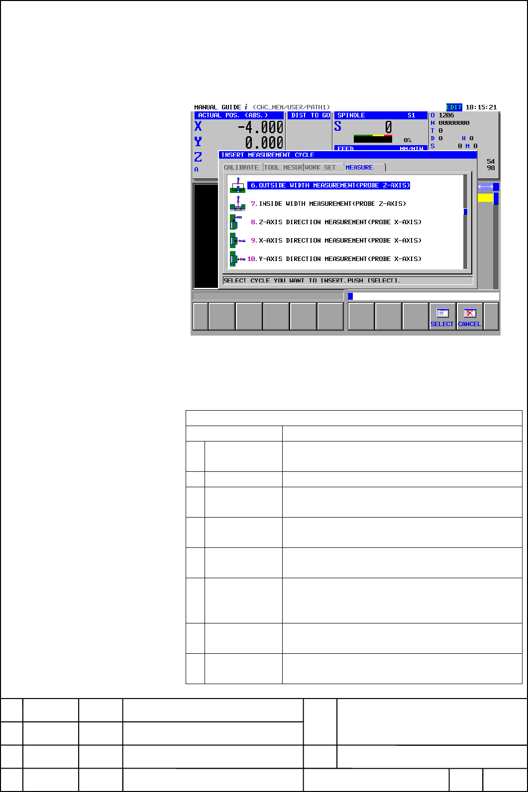
<3> Press the page key[↓] on this screen, the following screen appears.
At a selection screen of post-machining inspection menu for measurement
cycle, select
“6. OUTSIDE WIDTH MEASUREMENT (PROBE Z-AXIS)”
Measurement Operation
Input Item Meanings
Q Measurement
Condition
Measurement Condition (group number of setup
measurement condition)
D Protrude Width Actual protrude width
H Internal Point
X
Center point X at measurement
V Internal Point
Y
Center point Y at measurement
M Slant Angle
Groove, protrude angle (+X direction is 0°,
counterclockwise is the angle of +)
L Height of
Measurement
Position
Height of Z axis direction at measurement position
R Approach
distance
Moved distance from approach point to measurement
position of Z axis direction
F Moving speed at
measurement
Moving speed at measurement
Contents Summary of Manual Guide i Operators manual
- Page 1SET-UP GUIDANCE FUNCTIONS OPERATOR’S MANUAL B-63874EN-1/02
- Page 2• No part of this manual may be reproduced in any form. • All specifications and designs are subject to change without notice. The export of this product is subject to the authorization of the government of the country from where the product is exported. In this manual we have tried as much as possi
- Page 3B-63874EN-1/02 PREFACE PREFACE Using the set-up guidance functions of MANUAL GUIDE i requires the set-up guidance options. Probes, touch sensors, and other measuring instruments are required to enable the set-up guidance. Refer to the manual published by the machine tool builder of your machine for
- Page 4
- Page 5B-63874EN-1/02 TABLE OF CONTENTS TABLE OF CONTENTS PREFACE.................................................................................................. p-1 1 MANUAL MEASUREMENT FUNCTIONS..............................................1 1.1 SELECTING THE MEASURE SCREEN.............................
- Page 6TABLE OF CONTENTS B-63874EN-1/02 2.2.2 Probe Length Measurement................................................................................... 89 2.2.3 Stylus Ball Diameter Measurement....................................................................... 93 2.2.4 Stylus Ball Center Offset Measu
- Page 7B-63874EN-1/02 TABLE OF CONTENTS 2.8.3 End Face (Z-axis Direction) Measurement ......................................................... 219 2.8.4 Outside Diameter Measurement .......................................................................... 220 2.8.5 Inside Diameter Measurement............
- Page 8TABLE OF CONTENTS B-63874EN-1/02 4.1.1 Displaying the RESULT Screen.......................................................................... 271 4.1.2 Data Displayed on the RESULT Screen.............................................................. 272 4.1.3 Clearing Measurement Result List Data...
- Page 9B-63874EN-1/02 1.MANUAL MEASUREMENT FUNCTIONS 1 MANUAL MEASUREMENT FUNCTIONS -1-
- Page 101.MANUAL MEASUREMENT FUNCTIONS B-63874EN-1/02 1.1 SELECTING THE MEASURE SCREEN 1.1.1 Selecting CALIBRATE <1> The following main menu soft keys are displayed when the machine is in the manual operation mode. <2> Press the [MESURE] key. The menu for the measurement preparation function appears. <3> Us
- Page 11B-63874EN-1/02 1.MANUAL MEASUREMENT FUNCTIONS 1.1.2 Selecting TOOL MESUR <1> The following main menu soft keys are displayed when the machine is in the manual operation mode. <2> Press the [MESURE] key. The menu for the measurement preparation function appears. <3> Press the [→] menu select screen c
- Page 121.MANUAL MEASUREMENT FUNCTIONS B-63874EN-1/02 1.1.3 Selecting WORK SET <1> The following main menu soft keys are displayed when the machine is in the manual operation mode. <2> Press the [MESURE] key. The menu for the measurement preparation function appears. <3> Press the [→] cursor key on the meas
- Page 13B-63874EN-1/02 1.MANUAL MEASUREMENT FUNCTIONS 1.1.4 Selecting MEASURE <1> The following main menu soft keys are displayed when the machine is in the manual operation mode. <2> Press the [MESURE] key. The menu for the measurement preparation function appears. <3> Press the [→] cursor key on the measu
- Page 141.MANUAL MEASUREMENT FUNCTIONS B-63874EN-1/02 1.2 CALIBRATION 1.2.1 TOUCH SENSOR POSITION MEASUREMENT Measurement procedure <1> Select TOUCH SENSOR POSITION MEASUREMENT from the measurement preparation function menu. <2> Get the reference tool close to the touch sensor by moving it manually. NOTE Pl
- Page 15B-63874EN-1/02 1.MANUAL MEASUREMENT FUNCTIONS <6> Press the [MESURE] soft key. The probe touches the reference workpiece automatically, and the current position of the measurement point is displayed as the measurement result. <7> Press the [→] cursor key. The "SET" screen appears. <8> Specify a cond
- Page 161.MANUAL MEASUREMENT FUNCTIONS B-63874EN-1/02 <11>After entering the necessary data, press the [SET] soft key. The measurement result is set up as the measurement preparation data. Measurement Measurements are made as follows: First measurement cycle Second measurement cycle Tool Tool length α Measu
- Page 17B-63874EN-1/02 1.MANUAL MEASUREMENT FUNCTIONS 1.2.2 PROBE LENGTH CALIBRATION Measurement procedure <1> Select PROBE LENGTH CALIBRATION from the measurement preparation function menu. <2> Get the probe close to the measurement reference workpiece such as a ring gauge by moving it manually. NOTE Place
- Page 181.MANUAL MEASUREMENT FUNCTIONS B-63874EN-1/02 <5> Enter the height of the measurement reference workpiece in "REFERENCE WORK HEIGHT." <6> Press the [MESURE] soft key. The probe touches the reference workpiece automatically, and the current position of the measurement point is displayed as the measur
- Page 19B-63874EN-1/02 1.MANUAL MEASUREMENT FUNCTIONS <9> Select the "MEASURE CONDITION" for the item to which the measurement result is to be set. The currently set value for the probe length for the measurement condition appears. <10>After selecting the measurement condition, press the [SET] soft key. The
- Page 201.MANUAL MEASUREMENT FUNCTIONS B-63874EN-1/02 Measurement Measurements are made as follows: First measurement cycle Second measurement cycle Probe Probe α Measurement length β start point Workpiece γ top surface Reference workpiece Symbol in the Meaning explanation Feedrate in the first measurement
- Page 21B-63874EN-1/02 1.MANUAL MEASUREMENT FUNCTIONS 1.2.3 STYLUS BALL DIAMETER CALIBRATION Measurement procedure <1> Select STYLUS BALL DIAMETER CALIBRATION from the measurement preparation function menu. <2> Enter the diameter of the measurement reference workpiece in "REFERENCE WORK DIAMETER." <3> Press
- Page 221.MANUAL MEASUREMENT FUNCTIONS B-63874EN-1/02 <5> In "MEASURE CONDITION," select a measure condition. <6> Place the probe in the first measurement start position for the measurement reference workpiece such as a ring gauge by moving it manually. <7> In "1ST PT. MEASURE DIRECT," select a measurement
- Page 23B-63874EN-1/02 1.MANUAL MEASUREMENT FUNCTIONS <9> Perform measurement for the second, third, and fourth points in the same manner as for the first point. <10>Press the [→] cursor key. The "SET" screen appears. <11>Using a number, specify a condition for which the measurement result is to be set by s
- Page 241.MANUAL MEASUREMENT FUNCTIONS B-63874EN-1/02 <13>After selecting the measurement condition, press the [SET] soft key. The measurement result is set as the measurement preparation data. Measurement Measurements are made as follows: First measurement cycle Measurement Second measurement cycle start p
- Page 25B-63874EN-1/02 1.MANUAL MEASUREMENT FUNCTIONS 1.2.4 STYLUS OFFSETS CALIBRATION-A (*) The spindle orientation function is used for this function. Measurement procedure <1> Select STYLUS OFFSETS CALIBRATION-A from the measurement preparation function menu. <2> Enter the diameter of the measurement ref
- Page 261.MANUAL MEASUREMENT FUNCTIONS B-63874EN-1/02 <4> Press the [→] cursor key. The "SET" screen appears. <5> Specify a condition for which the measurement result is to be set by selecting it from the two or more "MEASURE CONDITION" items, using a number. The number corresponding to the measurement cond
- Page 27B-63874EN-1/02 1.MANUAL MEASUREMENT FUNCTIONS Measurement Measurements are made as follows: First measurement cycle Measurement Second measurement cycle start point α β Measurement γ surface Symbol in the Meaning explanation Feedrate in the first measurement cycle f1 Approach distance in the first m
- Page 281.MANUAL MEASUREMENT FUNCTIONS B-63874EN-1/02 1.2.5 STYLUS OFFSETS CALIBRATION-B NOTE It is necessary to place a reference workpiece such as a ring gauge accurately on the table whose center position is known. Measurement procedure <1> Select STYLUS OFFSETS CALIBRATION-B from the measurement prepara
- Page 29B-63874EN-1/02 1.MANUAL MEASUREMENT FUNCTIONS NOTE The same measurement procedure as for "STYLUS BALL DIAMETER CALIBRATION" applies to "STYLUS OFFSETS CALIBRATION-B." See "STYLUS BALL DIAMETER CALIBRATION" for details. <4> Press the [→] cursor key. The "SET" screen appears. <5> Using a number, speci
- Page 301.MANUAL MEASUREMENT FUNCTIONS B-63874EN-1/02 <7> After selecting the measurement condition, press the [SET] soft key. The measurement result is set as the measurement preparation data. Measurement Measurements are made as follows: NOTE The same measurement procedure as for STYLUS BALL DIAMETER CALI
- Page 31B-63874EN-1/02 1.MANUAL MEASUREMENT FUNCTIONS 1.3 TOOL MEASUREMENT Measurement procedure <1> Select TOOL MEASUREMENT from the tool measurement menu. <2> If a measurement tool was already selected, go to the “MEASURE” screen. <3> Place the spindle in a place where it is safe to exchange the tool. <4>
- Page 321.MANUAL MEASUREMENT FUNCTIONS B-63874EN-1/02 <9> In "MEASURE CONDITION," select a measure condition. <10>Set up "MEASURE CONDITION." If more than one measurement condition can be specified in "TOUCH SENSOR POSITION MEASUREMENT" for measurement preparation, specify which measurement condition is to
- Page 33B-63874EN-1/02 1.MANUAL MEASUREMENT FUNCTIONS <12>After performing measurement, press the [→] cursor key to select "T-TOOL." If you want to specify a milling tool offset number as the item for which the offset value is to be set, go to select "M-TOOL." NOTE With the CNC for a machining center, the “
- Page 341.MANUAL MEASUREMENT FUNCTIONS B-63874EN-1/02 <15>After entering the necessary data, press the [SET] soft key. The measurement result is set as the tool offset. NOTE When the "tool geometry/wear offset" function is available, the tool wear offset is specified as 0 if the offset obtained in measureme
- Page 35B-63874EN-1/02 1.MANUAL MEASUREMENT FUNCTIONS <19>In "OFFSET KIND," specify an offset value for which the measurement result is to be set. NOTE The "tool offset memory B" and "tool offset memory C" functions are options. (The "tool offset memory B" option is unavailable on the NC for complex machini
- Page 361.MANUAL MEASUREMENT FUNCTIONS B-63874EN-1/02 NOTE Before starting tool exchange, be sure to place the spindle in such a safe place that the tool will not touch any other machine portion or the workpiece. Similarly, before starting measurements, be sure to place the tool in such a safe place that th
- Page 37B-63874EN-1/02 1.MANUAL MEASUREMENT FUNCTIONS Measurement Measurements are made as follows: First measurement cycle Second measurement cycle Tool Tool length D α Measurement β start point α γ Touch Touch sensor sensor top surface Symbol in the Meaning explanation Feedrate in the first measurement cy
- Page 381.MANUAL MEASUREMENT FUNCTIONS B-63874EN-1/02 Referencing the tool offset value setting screen Press the [OFFSET] soft key on the tool measurement screen. The following screen appears. <1> The data displayed here is the same as for the tool offset value entry screen of the setting menu. <2> When the
- Page 39B-63874EN-1/02 1.MANUAL MEASUREMENT FUNCTIONS 1.4 WORK SET 1.4.1 SINGLE SURFACE MEASUREMENT PROBE Z-AXIS Measurement procedure <1> Select "SINGLE SURFACE MEASUREMENT PROBE Z- AXIS" from the centering menu select screen. <2> By moving the probe manually, get it close to the measurement point where me
- Page 401.MANUAL MEASUREMENT FUNCTIONS B-63874EN-1/02 <6> After entering "MEASURE DIRECTION," press, the [MESURE] soft key. The probe touches the measurement point automatically, and the current position of the measurement point is displayed as the measurement result. <7> After making measurements, press th
- Page 41B-63874EN-1/02 1.MANUAL MEASUREMENT FUNCTIONS <9> In "WORK COORDINATE NO. T," specify a workpiece coordinate system for which the measurement result is to be set. (Descriptions of values to be entered) For G54 → Key in '54'. For G59→ Key in '59'. If the coordinate system to be set is anything betwee
- Page 421.MANUAL MEASUREMENT FUNCTIONS B-63874EN-1/02 <11>In "WORK COORDINATE VALUE," specify what coordinates in the workpiece coordinate system are to be assigned to the measurement point. <12>Press the [SET] soft key. A value calculated from the measurement result and the value specified in "WORK COORIDA
- Page 43B-63874EN-1/02 1.MANUAL MEASUREMENT FUNCTIONS <14>The measurement result appears on the screen. If you want to make measurements only, quit the operation here. Set values in "WORK COORDINATE NO. M" and "WORK COORDINATE VALUE." <15>For explanations about what to set, see the specification of operatio
- Page 441.MANUAL MEASUREMENT FUNCTIONS B-63874EN-1/02 Measurement Measurements are made as follows: ● Measuring the end face along the X- or Y-axis First measurement cycle Measurement Second measurement cycle start point α β Measurement γ surface Symbol in the Meaning explanation Feedrate in the first measu
- Page 45B-63874EN-1/02 1.MANUAL MEASUREMENT FUNCTIONS ● Measuring the end face along the Z-axis First measurement cycle Second measurement cycle Measurement start point α β Measurement γ surface <1> Get the probe close to the measurement position by moving it manually. <2> When measurement is started, the p
- Page 461.MANUAL MEASUREMENT FUNCTIONS B-63874EN-1/02 1.4.2 SINGLE SURFACE MEASUREMENT PROBE Measurement procedure <1> Select "SINGLE SURFACE MEASUREMENT PROBE X- AXIS" from the centering function menu select screen. The contents of this screen and what data is input on it are the same as for "SINGLE SURFAC
- Page 47B-63874EN-1/02 1.MANUAL MEASUREMENT FUNCTIONS <3> Then, the probe returns through the distance β at the rapid traverse rate. Within the range (β + γ) from the current position, the probe moves at a feedrate of f2 to perform the second measurement cycle. <4> After the second measurement cycle, the pr
- Page 481.MANUAL MEASUREMENT FUNCTIONS B-63874EN-1/02 1.4.3 OUTSIDE DIAMETER MEASUREMENT Measurement procedure <1> Select "OUTSIDE DIAMETER MEASUREMENT" from the centering function menu select screen. <2> By moving the probe manually, get it close to the measurement point so that measurement is possible wit
- Page 49B-63874EN-1/02 1.MANUAL MEASUREMENT FUNCTIONS <5> When the cursor is placed on "1ST PT. MEASURE DIRECT," the following screen appears. <6> Select a measurement direction from the [+X], [-X], [+Y], [-Y], [+Z], and [-Z] soft keys. Usually, no change is needed. If you want to make measurements on anoth
- Page 501.MANUAL MEASUREMENT FUNCTIONS B-63874EN-1/02 <8> Pressing the [↓] cursor key displays a guide chart for "2ND PT. MEASURE DIRECT." <9> By moving the probe manually, get it close to the second measurement point so that measurement is possible with the movement of the probe along the axis in one direc
- Page 51B-63874EN-1/02 1.MANUAL MEASUREMENT FUNCTIONS <12>After measurements are made, placing the cursor on a measurement point displayed on the "MEASURE" screen re- displays the measurement result on that point. Under this condition, pressing the [MESURE] soft key triggers re- measurements on the point. <
- Page 521.MANUAL MEASUREMENT FUNCTIONS B-63874EN-1/02 <14>Based on the measurement results on the four points, the center position is displayed on the screen. If you want to perform measurements only, quit the operation here. The data to be displayed varies depending on what is entered in "MEASURE DIRECTION
- Page 53B-63874EN-1/02 1.MANUAL MEASUREMENT FUNCTIONS <19>Pressing the [→] cursor key displays the "M-WORK" screen, on which a milling tool offset number can be specified. For explanations about the operating procedure for this screen, see those for the "T-WORK" screen. NOTE With the CNC for a lathe, the “M
- Page 541.MANUAL MEASUREMENT FUNCTIONS B-63874EN-1/02 Measurement Measurements are made as follows: If [ENABLE] is selected for "ORIENTED SPINDLE STOP," the following operations occur. <1> If the measurement plane is the X-Y plane, and measurements are to be made in the "+X" direction, before starting measu
- Page 55B-63874EN-1/02 1.MANUAL MEASUREMENT FUNCTIONS 1.4.4 INSIDE DIAMETER MEASUREMENT Measurement procedure <1> Select "INSIDE DIAMETER MEASUREMENT" from the centering function menu select screen. The items displayed on this screen and the operating procedure for them are the same as for OUTSIDE DIAMETER
- Page 561.MANUAL MEASUREMENT FUNCTIONS B-63874EN-1/02 1.4.5 OUTSIDE WIDTH MEASUREMENT Measurement procedure <1> Select "OUTSIDE WIDTH MEASUREMENT" from the centering function menu select screen. <2> By moving the probe manually, get it close to the first measurement point so that measurement is possible wit
- Page 57B-63874EN-1/02 1.MANUAL MEASUREMENT FUNCTIONS (If [Y-Z Z] is selected) <4> Set up "MEASURE CONDITION." <5> Placing the cursor on "1ST PT. MEASURE DIRECT" displays the following screen. <6> Select a measurement direction from the [+X], [-X], [+Y], [-Y], [+Z], and [-Z] soft keys. Usually, no change is
- Page 581.MANUAL MEASUREMENT FUNCTIONS B-63874EN-1/02 <8> Pressing the [↓] cursor key displays a guide chart for "2ND PT. MEASURE DIRECT." <9> By moving the probe manually, get it close to the second measurement point so that measurement is possible with the movement of the probe along the axis in one direc
- Page 59B-63874EN-1/02 1.MANUAL MEASUREMENT FUNCTIONS <11>After measurements, press the [→] cursor key to display the "T- WORK" screen. NOTE With the CNC for a machining center, the “T- WORK” screen is not displayed. <12>Based on the measurement results on the two points, the center position and width are d
- Page 601.MANUAL MEASUREMENT FUNCTIONS B-63874EN-1/02 (If [Y-Z Z] is selected) <13>In "WORK COORDINATE NO. T," specify the workpiece coordinate system for which the measurement result is to be set. <14>When a workpiece coordinate system is selected, the current workpiece coordinate system data is displayed
- Page 61B-63874EN-1/02 1.MANUAL MEASUREMENT FUNCTIONS Measurement Measurements are made as follows: NOTE The same measurement procedure as for SINGLE SURFACE MEASUREMENT PROBE Z-AXIS applies to the above measurements. See "SINGLE SURFACE MEASUREMENT PROBE Z-AXIS" for details. - 53 -
- Page 621.MANUAL MEASUREMENT FUNCTIONS B-63874EN-1/02 1.4.6 INSIDE WIDTH MEASUREMENT Measurement procedure <1> Select "INSIDE WIDTH MEASUREMENT" from the centering function menu select screen. NOTE The items displayed on this screen and the operation procedure for them are the same as for OUTSIDE WIDTH MEAS
- Page 63B-63874EN-1/02 1.MANUAL MEASUREMENT FUNCTIONS 1.4.7 C AXIS PHASE MEASUREMENT OF OUTSIDE GROOVE Measurement procedure <1> Select "C AXIS PHASE MEASUREMENT OF OUTSIDE GROOVE" from the workpiece measurement menu. <2> By moving the probe manually, get it close to the first measurement point so that meas
- Page 641.MANUAL MEASUREMENT FUNCTIONS B-63874EN-1/02 <6> Pressing the [↓] cursor key displays a guide chart for "2ND PT. MEASURE DIRECT." <7> Retract the probe in the Z-axis direction while keeping it stationary with respect to the X- and Y-axes, and then rotate it around the C-axis. <8> By moving the prob
- Page 65B-63874EN-1/02 1.MANUAL MEASUREMENT FUNCTIONS <10>After measurements, press the [→] cursor key to display the "T- WORK" screen. NOTE With the CNC for a machining center, the “T- WORK” screen is not displayed. <11>Based on the measurement results on the two points, the center angle is displayed on th
- Page 661.MANUAL MEASUREMENT FUNCTIONS B-63874EN-1/02 For explanations about the operating procedure for this screen, see those for the "T-WORK" screen. NOTE With the CNC for a lathe, the “M-WORK” screen is not displayed. Measurement Measurements are made as follows: NOTE The same measurement procedure as f
- Page 67B-63874EN-1/02 1.MANUAL MEASUREMENT FUNCTIONS 1.4.8 C AXIS PHASE MEASUREMENT OF INSIDE CAVE Measurement procedure <1> Select "C AXIS PHASE MEASUREMENT OF INSIDE CAVE" from the workpiece measurement menu. NOTE The items displayed on this screen and the operating procedure for them are the same as for
- Page 681.MANUAL MEASUREMENT FUNCTIONS B-63874EN-1/02 1.5 MEASURE 1.5.1 SINGLE SURFACE MEASUREMENT PROBE Z-AXIS Measurement procedure <1> Select "SINGLE SURFACE MEASUREMENT PROBE Z- AXIS" from the post-machining inspection menu select screen. The contents of the "MEASURE" screen are the same as for "SINGLE
- Page 69B-63874EN-1/02 1.MANUAL MEASUREMENT FUNCTIONS <4> Select a value for "OFFSET KIND," using the soft keys. NOTE 1 The "Y-axis offset" function is an option. 2 The "tool geometry/wear offset" function is an option. If this option is unavailable, neither "GEOMETORY" nor "WEAR" is displayed. <5> In "TARG
- Page 701.MANUAL MEASUREMENT FUNCTIONS B-63874EN-1/02 <6> After entering the necessary data, press the [SET] soft key. The measurement result is set as the tool offset value. NOTE A value displayed as the setting value is added to the offset value for the item specified in OFFSET KIND. <7> Pressing the [→]
- Page 71B-63874EN-1/02 1.MANUAL MEASUREMENT FUNCTIONS <9> Select a value for "OFFSET KIND," using the soft keys. NOTE The "tool offset memory B" and "tool offset memory C" functions are options. (The "tool offset memory B" option is unavailable on the NC for complex machining.) <10>In "TARGET VALUE," specif
- Page 721.MANUAL MEASUREMENT FUNCTIONS B-63874EN-1/02 <11>After entering the necessary data, press the [SET] soft key. The measurement result is set as the tool offset value. NOTE A value displayed as the setting value is added to the offset value specified in the item for which the setting value is to be s
- Page 73B-63874EN-1/02 1.MANUAL MEASUREMENT FUNCTIONS 1.5.2 SINGLE SURFACE MEASUREMENT PROBE X-AXIS Measurement procedure <1> Select "SINGLE SURFACE MEASUREMENT PROBE X- AXIS" from the post-machining inspection menu select screen. The contents of this screen and the data entered on it are the same as for "S
- Page 741.MANUAL MEASUREMENT FUNCTIONS B-63874EN-1/02 1.5.3 OUTSIDE DIAMETER MEASUREMENT Measurement procedure <1> Select "OUTSIDE DIAMETER MEASUREMENT" from the post-machining inspection menu select screen. The contents of this "MEASURE" screen are the same as for "OUTSIDE DIAMETER MEASUREMENT" on the "WOR
- Page 75B-63874EN-1/02 1.MANUAL MEASUREMENT FUNCTIONS <5> In "TARGET VALUE," specify the desired post-machining outside diameter value. After the value is entered, the value obtained by dividing the difference between the target value and the measurement result by 2 then multiplying by the offset value is d
- Page 761.MANUAL MEASUREMENT FUNCTIONS B-63874EN-1/02 NOTE With the CNC for a lathe, the “M-TOOL” screen is not displayed. <8> In "TOOL OFFSET NO. M-SIDE," specify a milling tool offset number. When an offset number is entered, the current offset value for the offset number is displayed on the right section
- Page 77B-63874EN-1/02 1.MANUAL MEASUREMENT FUNCTIONS 1.5.4 INSIDE DIAMETER MEASUREMENT Measurement procedure <1> Select "INSIDE DIAMETER MEASUREMENT" from the post- machining inspection menu select screen. The items displayed on this screen and the operating procedure for them are the same as for OUTSIDE D
- Page 781.MANUAL MEASUREMENT FUNCTIONS B-63874EN-1/02 1.5.5 OUTSIDE WIDTH MEASUREMENT Measurement procedure <1> Select "OUTSIDE WIDTH MEASUREMENT" from the post- machining inspection menu select screen. The contents of this "MEASURE" screen are the same as for "OUTSIDE WIDTH MEASUREMENT" on the "WORK SET" m
- Page 79B-63874EN-1/02 1.MANUAL MEASUREMENT FUNCTIONS <6> In "TARGET VALUE," specify the desired post-machining groove width value. After the value is entered, the value obtained by multiplying a difference between the target value and the measurement result by the offset value is displayed as the setting v
- Page 801.MANUAL MEASUREMENT FUNCTIONS B-63874EN-1/02 NOTE With the CNC for a lathe, the “M-TOOL” screen is not displayed. <9> Enter a milling tool offset number in "TOOL OFFSET NO. M- SIDE." <10>When an offset number is entered, the current offset value for the offset number is displayed on the right secti
- Page 81B-63874EN-1/02 1.MANUAL MEASUREMENT FUNCTIONS 1.5.6 INSIDE WIDTH MEASUREMENT Measurement procedure <1> Select "INSIDE WIDTH MEASUREMENT" from the post- machining inspection menu select screen. The items displayed on this screen and the operating procedure for them are the same as for OUTSIDE WIDTH M
- Page 822.MEASUREMENT CYCLE B-63874EN-1/02 2 MEASUREMENT CYCLE - 74 -
- Page 83B-63874EN-1/02 2.MEASUREMENT CYCLE 2.1 MEASUREMENT SCREEN SELECTION In the edit mode, the following main menu soft keys are displayed: (First page: Basic programming menu) - When you press the [+] soft key at the rightmost position, the soft keys for the second page appear. (Second page: Programming
- Page 842.MEASUREMENT CYCLE B-63874EN-1/02 When you press the page key [↓] on this screen, the following screen appears: When you select a cycle to be inserted then press the [SELECT] soft key, the input screen for the selected cycle appears. Selecting a tool measurement menu item When you press the cursor
- Page 85B-63874EN-1/02 2.MEASUREMENT CYCLE Selecting a centering menu item When you press the cursor key [→] while the tool measurement menu selection screen is displayed, the following screen appears: When you press the page key [↓] on this screen, the following screen appears: When you press the page key
- Page 862.MEASUREMENT CYCLE B-63874EN-1/02 When you press the page key [↓] once again on this screen, the following screen appears: When you select a cycle to be inserted then press the [SELECT] soft key, the input screen for the selected cycle appears. Selecting a post-machining inspection menu item When y
- Page 87B-63874EN-1/02 2.MEASUREMENT CYCLE When you press the page key [↓] on this screen, the following screen appears: When you press the page key [↓] again on this screen, the following screen appears: When you select a cycle to be inserted then press the [SELECT] soft key, the input screen for the selec
- Page 882.MEASUREMENT CYCLE B-63874EN-1/02 2.2 CALIBRATION (PROBE Z-AXIS DIRECTION) 2.2.1 Touch Sensor Position Measurement When the reference tool is oriented in the Z-axis direction, the position of the touch sensor for tool measurement is measured. Measurement motion screen When you select "TOUCH SENSOR
- Page 89B-63874EN-1/02 2.MEASUREMENT CYCLE - REF TOOL RADIUS Enter the dimension of the reference tool in the X-axis and Y-axis directions. Enter a numeric value. - SPECIFY OF MEAS. PT. Select a measurement position specification method from the soft keys below. By default, "SETTIN" is selected. When "SETTI
- Page 902.MEASUREMENT CYCLE B-63874EN-1/02 Setting screen - SWITCH DEST. Specify a setting destination for setting calibration data. Make a selection from the soft keys below. By default, "OFFSET" is selected. NOTE If "REF. VALUE" is selected, the result of measurement is set as the calibration data referen
- Page 91B-63874EN-1/02 2.MEASUREMENT CYCLE ±) - FEED BACK RANGE (± If an error obtained from measurement is not within the OK range but is within this feedback range, the measured value is set in the setting destination. If an error obtained from measurement exceeds the feedback range, an alarm is issued. E
- Page 922.MEASUREMENT CYCLE B-63874EN-1/02 Measurement motion Measurement motion is described below. - Measurement of the touch sensor position for measurement in the -Z-axis direction <1> A rapid movement is made from the current position to the approach point (X coordinate,Y coordinate). Here, the approac
- Page 93B-63874EN-1/02 2.MEASUREMENT CYCLE The symbols used above have the following meanings: A: Touch sensor position. If "SETTIN" is selected in "SPECIFY OF MEAS. PT.", A represents the "sensor position for measurement in the -Z direction" of the touch sensor position in the specified measurement conditi
- Page 942.MEASUREMENT CYCLE B-63874EN-1/02 - Measurement of the touch sensor position for measurement in the +X-axis direction <1> A rapid movement is made from the current position to the approach point (X coordinate,Y coordinate). Here, the approach point (X coordinate) represents (touch sensor position A
- Page 95B-63874EN-1/02 2.MEASUREMENT CYCLE - Measurement of the touch sensor position for measurement in the -X-axis direction <1> A rapid movement is made from the current position to the approach point (X coordinate,Y coordinate). Here, the approach point (X coordinate) represents (touch sensor position A
- Page 962.MEASUREMENT CYCLE B-63874EN-1/02 - Measurement of the touch sensor position for measurement in the -Y-axis direction <1> A rapid movement is made from the current position to the approach point (X coordinate,Y coordinate). Here, the approach point (X coordinate) represents the touch sensor positio
- Page 97B-63874EN-1/02 2.MEASUREMENT CYCLE 2.2.2 Probe Length Measurement When the probe is oriented in the Z-axis direction, a probe length measurement is made. Measurement motion screen When you select "PROBE LENGTH CALIBRATION (PROBE Z- AXIS)" on the calibration menu selection screen of the measurement c
- Page 982.MEASUREMENT CYCLE B-63874EN-1/02 Setting screen - OK RANGE (±±) Specify an allowable range of errors obtained from measurement. If the difference between the obtained result of measurement and the probe length of the calibration data currently specified with "MEASUREMENT COND." is within this allo
- Page 99B-63874EN-1/02 2.MEASUREMENT CYCLE Measurement motion Measurement motion is described below. <1> A rapid movement is made from the current position to the point specified by "MEASURE POINT X" and "MEASURE POINT Y". <2> In the Z-axis direction, a rapid movement is made to the approach point (Z coordi
- Page 1002.MEASUREMENT CYCLE B-63874EN-1/02 The symbols used above have the following meanings: T: Height of the surface on which the reference workpiece is placed. ("Machine coordinate of the table surface when a measurement is made in the Z-axis direction" in the measurement condition is referenced.) f: Va
- Page 101B-63874EN-1/02 2.MEASUREMENT CYCLE 2.2.3 Stylus Ball Diameter Measurement The diameters of the stylus ball in the X-axis direction and Y-axis direction are measured. When you select "STYLUS BALL DIAMETER CALIBRATION (PROBE Z-AXIS)" on the calibration menu selection screen of the measurement cycle, t
- Page 1022.MEASUREMENT CYCLE B-63874EN-1/02 - MOVING MEAS. SPEED Enter a feedrate at measurement. Enter a numeric value. - MEASUREMENT POINT Specify the number of measurement points. Enter a numeric value (1 to 4). When no value is entered, 4 (four-point measurement) is assumed. Setting screen - OK RANGE (±±
- Page 103B-63874EN-1/02 2.MEASUREMENT CYCLE NOTE Two stylus ball diameters are set in the calibration data: one in the first axis direction, and the other in the second axis direction. So, the diameter values obtained from measurement are compared in the two directions. If one of the diameters exceeds the fe
- Page 1042.MEASUREMENT CYCLE B-63874EN-1/02 <7> A similar measurement is made in the -X-axis direction and ±Y- axis directions. <8> After the first measurement, a center position for the second measurement is calculated from the measurement result of each point. <9> In the +X-axis direction, a movement is ma
- Page 105B-63874EN-1/02 2.MEASUREMENT CYCLE f: Value of “FEED-RATE FOR 1ST MEASUREMENT" in the measurement condition of the group number specified in "MEASUREMENT COND." α: Value of “APPROACH DISTANCE FOR 1ST MEASUREMENT" in the measurement condition of the group number specified in "MEASUREMENT COND." β: Va
- Page 1062.MEASUREMENT CYCLE B-63874EN-1/02 2.2.4 Stylus Ball Center Offset Measurement-A The offset between the center of the stylus ball and the center of the spindle is measured. NOTE By using the spindle orientation function, the machine tool builder needs to perform spindle positioning at 0° or 180° bas
- Page 107B-63874EN-1/02 2.MEASUREMENT CYCLE - HEIGHT OF MEAS. PT. Enter the height of a measurement point in the Z-axis direction. Enter a numeric value. - APROCH DISTANCE Specify the move distance from the approach point to the measurement point in the Z-axis direction. Enter a numeric value. - MOVING MEAS.
- Page 1082.MEASUREMENT CYCLE B-63874EN-1/02 ±) - FEED BACK RANGE (± If an offset obtained from measurement is not within the OK range but is within this feedback range, the offset is set in the setting destination. If an offset obtained from measurement exceeds the feedback range, an alarm is issued. Enter a
- Page 109B-63874EN-1/02 2.MEASUREMENT CYCLE Measurement motion Measurement motion is described below. <1> The reference workpiece is placed on the table, then this measurement cycle is executed. <2> When this measurement cycle is executed, a rapid movement is first made from the current position to the point
- Page 1102.MEASUREMENT CYCLE B-63874EN-1/02 The symbols used above have the following meanings: fa: Value of "FEED-RATE FOR APPROACHING START POINT" in the measurement condition of the group number specified in "MEASUREMENT COND." Rapid traverse rate when bit 2 (RPDF) of parameter No. 12380 is set to 1. fb:
- Page 111B-63874EN-1/02 2.MEASUREMENT CYCLE Measurement result When G2003 is executed, center offsets of the stylus ball in the X- axis and Y-axis directions are found from measured values, and are output to the calibration data and macro variables for the result of measurement. - 103 -
- Page 1122.MEASUREMENT CYCLE B-63874EN-1/02 2.2.5 Stylus Ball Center Offset Measurement-B The offset between the center of the stylus ball and the center of the spindle is measured. NOTE A reference workpiece needs to be accurately placed on a table whose center position is known. When you select "STYLUS OFF
- Page 113B-63874EN-1/02 2.MEASUREMENT CYCLE - APROCH CENTER PT. Y Enter the Y coordinate of the center of the reference workpiece. Enter a numeric value. - HEIGHT OF MEAS. PT. Enter the height of a measurement point in the Z-axis direction. Enter a numeric value. - APROCH DISTANCE Specify the move distance f
- Page 1142.MEASUREMENT CYCLE B-63874EN-1/02 ±) - FEED BACK RANGE (± If an offset obtained from measurement is not within the OK range but is within this feedback range, the offset is set in the setting destination. If an offset obtained from measurement exceeds the feedback range, an alarm is issued. Enter a
- Page 115B-63874EN-1/02 2.MEASUREMENT CYCLE Measurement motion Measurement motion is described below. <1> The reference workpiece is placed on the table, then this measurement cycle is executed. <2> When this measurement cycle is executed, a rapid movement is first made from the current position to the point
- Page 1162.MEASUREMENT CYCLE B-63874EN-1/02 α: Value of “APPROACH DISTANCE FOR 1ST MEASUREMENT" in the measurement condition of the group number specified in "MEASUREMENT COND." β: Value of "ESCAPING DISTANCE FOR 1ST MEASUREMENT" in the measurement condition of the group number specified in "MEASUREMENT COND
- Page 117B-63874EN-1/02 2.MEASUREMENT CYCLE 2.3 TOOL MEASUREMENT (TOOL Z-AXIS DIRECTION) 2.3.1 Milling Tool Measurement When the milling tool is oriented in the Z-axis direction, its figures in the tool length direction and tool radius direction are measured. Measurement motion screen When you select "MILLIN
- Page 1182.MEASUREMENT CYCLE B-63874EN-1/02 - SPECIFY OF X SHIFT Select a method of specifying the shift amount from the X coordinate of the touch sensor position for tool measurement to the X coordinate of the tool measurement position. By default, [AUTO] is selected. Choose from the soft keys. When [AUTO]
- Page 119B-63874EN-1/02 2.MEASUREMENT CYCLE Input screen for automatic tool offset value setting (turning side) This screen enables specification for setting a measured value as a tool offset value on the turning side. NOTE With the CNC for a machining center, the "TOOL T" screen is not displayed. - COMP. NU
- Page 1202.MEASUREMENT CYCLE B-63874EN-1/02 - SETTING DEST. (T) Specify a tool offset item in which the result of measurement is to be set. Select a desired item from the following soft keys: NOTE When the tool geometry and wear compensation options are enabled, and a compensation value obtained from measure
- Page 121B-63874EN-1/02 2.MEASUREMENT CYCLE Processing when the OK range and the feedback range are 0 When the Ok range and the feedback range are set to 0, the processing below is performed. <1> When both the OK range and the feedback are set to 0 The result of measurement is not set in the setting destinat
- Page 1222.MEASUREMENT CYCLE B-63874EN-1/02 Input screen for automatic tool offset value setting (milling side) This screen enables specification for setting a measured value as a tool offset value on the milling side. NOTE 1 With the CNC for a lathe, the "TOOL M" screen is not displayed. 2 "32 tool compensa
- Page 123B-63874EN-1/02 2.MEASUREMENT CYCLE Measurement motion Measurement motion is described below. - Measurement of an offset value in the -Z-axis direction (measurement of an offset value in the tool length direction) - When [AUTO] is selected in "SPECIFY OF X, Y, and Z SHIFT" The measurement motion desc
- Page 1242.MEASUREMENT CYCLE B-63874EN-1/02 - Measurement of an offset value in the -Z-axis direction (measurement of an offset value in the tool length direction) - When a soft key other than [AUTO] is selected in "SPECIFY OF X, Y, and Z SHIFT" If the X coordinate of the "sensor position for measurement in
- Page 125B-63874EN-1/02 2.MEASUREMENT CYCLE <4> Next, a rapid return movement is made by β, and a measurement is made in the range from that position to (β + γ) at the specified feedrate F. (Second measurement) <5> Then, a rapid return movement is made by ε in the +Z-axis direction. • If [OFSET-] is selected
- Page 1262.MEASUREMENT CYCLE B-63874EN-1/02 - Measurement of an offset value in the -X-axis direction (measurement of an offset value in the tool radius direction) The measurement motion described below is made when [AUTO] is selected in all input items of “SPECIFY OF X SHIFT”, “SPECIFY OF Y SHIFT”, and “SPE
- Page 127B-63874EN-1/02 2.MEASUREMENT CYCLE <5> Then, a rapid return movement is made by ε in the +X-axis direction. If the coordinates of the "sensor position for measurement in the -X direction" of the touch sensor position are shifted from the coordinates of the tool measurement position, specify the shif
- Page 1282.MEASUREMENT CYCLE B-63874EN-1/02 ε: Value of "ESCAPING DISTANCE FOR 2ND MEASUREMENT" in the measurement condition of the group number specified in "MEASUREMENT COND." OHSH : Tool length direction offset value OFSD : Tool radius direction offset value G code format When you press the INSERT key aft
- Page 129B-63874EN-1/02 2.MEASUREMENT CYCLE 2.3.2 Turning Tool Measurement When the turning tool is oriented in the Z-axis direction, its figures in the Z-axis and X-axis directions are measured. Measurement motion screen When you select "TURNING TOOL MEASUREMENT (TOOL Z- AXIS)" on the tool measurement menu
- Page 1302.MEASUREMENT CYCLE B-63874EN-1/02 by the next item "OFFSET/DIFFERENCE X" from the X coordinate of the touch sensor position. - OFFSET/DIFFERENCE X This item is displayed when [INPUT] or [DIFFER] is selected in "SPECIFY OF X SHIFT". When [INPUT] is selected, enter the shift amount from the X coordin
- Page 131B-63874EN-1/02 2.MEASUREMENT CYCLE To the other items, the descriptions in "Milling Tool Measurement" are applied. - 123 -
- Page 1322.MEASUREMENT CYCLE B-63874EN-1/02 Measurement motion Measurement motion is described below. - Measurement of an offset value in the +X-axis direction Z X The measurement motion described below is made when [AUTO] is selected in all input items of “SPECIFY OF X SHIFT”, “SPECIFY OF Y SHIFT”, and “SPE
- Page 133B-63874EN-1/02 2.MEASUREMENT CYCLE <5> Then, a rapid return movement is made by ε in the -X-axis direction. If the coordinates of the "sensor position for measurement in the +X direction" of the touch sensor position are shifted from the coordinates of the tool measurement position, specify the shif
- Page 1342.MEASUREMENT CYCLE B-63874EN-1/02 - Measurement of an offset value in the -Z-axis direction Z X The measurement motion described below is made when [AUTO] is selected in all input items of “SPECIFY OF X SHIFT”, “SPECIFY OF Y SHIFT”, and “SPECIFY OF Z SHIFT”. <1> A rapid movement is made from the cu
- Page 135B-63874EN-1/02 2.MEASUREMENT CYCLE If the coordinates of the "sensor position for measurement in the -Z direction" of the touch sensor position are shifted from the coordinates of the tool measurement position, specify the shift in "SPECIFY OF X, Y, or Z SHIFT". For example, the motion described bel
- Page 1362.MEASUREMENT CYCLE B-63874EN-1/02 Measurement result When G2011 is executed, the result of measurement is output to macro variables for the result of measurement and as a specified tool offset value. - 128 -
- Page 137B-63874EN-1/02 2.MEASUREMENT CYCLE 2.4 WORK SET (PROBE Z-AXIS DIRECTION) 2.4.1 End Face (X-axis Direction) Measurement The position of an end face in the X-axis direction is measured. When you select "X-AXIS DIRECTION WORK SETUP (PROBE Z- AXIS)" on the centering menu selection screen of the measurem
- Page 1382.MEASUREMENT CYCLE B-63874EN-1/02 Input screen for automatic workpiece offset value setting (turning side) This screen enables specification for setting a measured value as a workpiece origin offset value on the turning side. NOTE With the CNC for a machining center, the "WORK T" screen is not disp
- Page 139B-63874EN-1/02 2.MEASUREMENT CYCLE - OK RANGE (±) Specify an allowable range of errors obtained from measurement. If the difference between the obtained result of measurement and the correct coordinate (input value "MEASURE POINT") is within this allowable range, the absence of errors is assumed, an
- Page 1402.MEASUREMENT CYCLE B-63874EN-1/02 Input screen for automatic workpiece offset value setting (milling side) This screen enables specification for setting a measured value as a workpiece origin offset value on the milling side. The descriptions of the input items are the same as for the turning side.
- Page 141B-63874EN-1/02 2.MEASUREMENT CYCLE Measurement motion Measurement motion is described below. <1> A rapid movement is made from the current position to the approach point (X coordinate,Y coordinate). Here, the approach point (X coordinate) represents ("MEASURE POINT X" - α) when the measurement direc
- Page 1422.MEASUREMENT CYCLE B-63874EN-1/02 G code format When you press the INSERT key after entering necessary data, a G code program in the following format is stored in the machining program memory: G2020 Q P H V L R F W I S Y U J K E ; Measurement result When G2020 is executed, the result of measurement
- Page 143B-63874EN-1/02 2.MEASUREMENT CYCLE 2.4.2 End Face (Y-axis Direction) Measurement The position of an end face in the Y-axis direction is measured. When you select "Y-AXIS DIRECTION WORK SETUP (PROBE Z- AXIS)" on the centering menu selection screen of the measurement cycle, the following screen appear
- Page 1442.MEASUREMENT CYCLE B-63874EN-1/02 Measurement motion <1> A rapid movement is made from the current position to the approach point (X coordinate,Y coordinate). Here, the approach point (X coordinate) is the same as "MEASURE POINT X". The approach point (Y coordinate) represents ("MEASURE POINT Y" –
- Page 145B-63874EN-1/02 2.MEASUREMENT CYCLE 2.4.3 End Face (Z-axis Direction) Measurement The position of an end face in the Z-axis direction is measured. When you select "Z-AXIS DIRECTION WORK SETUP (PROBE Z- AXIS)" on the centering menu selection screen of the measurement cycle, the following screen appear
- Page 1462.MEASUREMENT CYCLE B-63874EN-1/02 Measurement motion Measurement motion is described below. <1> A rapid movement is made from the current position to the point specified by "MEASURE POINT X" and "MEASURE POINT Y". <2> In the Z-axis direction, a rapid movement is made to the approach point (Z coordi
- Page 147B-63874EN-1/02 2.MEASUREMENT CYCLE 2.4.4 Outside Diameter Measurement When the probe is oriented in the Z-axis direction, the center position of the outside diameter of a circle is measured. When you select "OUTSIDE DIAMETER WORK SETUP (PROBE Z-AXIS)" on the centering menu selection screen of the me
- Page 1482.MEASUREMENT CYCLE B-63874EN-1/02 - MOVING MEAS. SPEED Enter a feedrate for measurement. Enter a numeric value. - MEASUREMENT POINT Specify the number of measurement points. Enter a numeric value (1 to 4). - SPINDLE ORIENTATION Specify whether to perform spindle orientation for each measurement poi
- Page 149B-63874EN-1/02 2.MEASUREMENT CYCLE - WORK COORD. VALUE Y Specify the Y coordinate of the measurement point in a specified workpiece coordinate system. Enter a numeric value. - OK RANGE (±) Specify an allowable range of errors obtained from measurement. If the difference between the center coordinate
- Page 1502.MEASUREMENT CYCLE B-63874EN-1/02 Input screen for automatic workpiece offset value setting (milling side) This screen enables specification for setting a measured value as a workpiece origin offset value on the milling side. The descriptions of the input items are the same as for the turning side.
- Page 151B-63874EN-1/02 2.MEASUREMENT CYCLE Measurement motion Measurement motion is described below. <1> A rapid movement is made from the current position to the point specified by ("CENTER POINT X" + ("OUTSIDE DIAMETER"/2 + α +r)) in the X-axis direction and by "CENTER POINT Y" in the Y-axis direction. <2
- Page 1522.MEASUREMENT CYCLE B-63874EN-1/02 β: Value of "ESCAPING DISTANCE FOR 1ST MEASUREMENT" in the measurement condition of the group number specified in "MEASUREMENT COND." γ: Value of "OVERLAP DISTANCE FOR MEASUREMENT" in the measurement condition of the group number specified in "MEASUREMENT COND." ε:
- Page 153B-63874EN-1/02 2.MEASUREMENT CYCLE G code format When you press the INSERT key after entering necessary data, a G code program in the following format is stored in the machining program memory: G2023 Q D H V L R F P M W I J S Y U A B K E ; Measurement result When G2023 is executed, the center of the
- Page 1542.MEASUREMENT CYCLE B-63874EN-1/02 2.4.5 Inside Diameter Measurement When the probe is oriented in the Z-axis direction, the center position of the inside diameter of a circle is measured. When you select "INSIDE DIAMETER WORK SETUP (PROBE Z- axis)" on the centering menu selection screen of the meas
- Page 155B-63874EN-1/02 2.MEASUREMENT CYCLE Measurement motion Measurement motion is described below. <1> A rapid movement is made from the current position to the point specified by ("CENTER POINT X" + ("INSIDE DIAMETER"/2 - α -r)) in the X-axis direction and by "CENTER POINT Y" in the Y-axis direction. <2>
- Page 1562.MEASUREMENT CYCLE B-63874EN-1/02 β: Value of "ESCAPING DISTANCE FOR 1ST MEASUREMENT" in the measurement condition of the group number specified in "MEASUREMENT COND." ε: Value of "ESCAPING DISTANCE FOR 2ND MEASUREMENT" in the measurement condition of the group number specified in "MEASUREMENT COND
- Page 157B-63874EN-1/02 2.MEASUREMENT CYCLE 2.4.6 Outside Width Measurement When the probe is oriented in the Z-axis direction, the center position of a projection width is measured. When you select "OUTSIDE WIDTH WORK SETUP (PROBE Z- AXIS)" on the centering menu selection screen of the measurement cycle, th
- Page 1582.MEASUREMENT CYCLE B-63874EN-1/02 Input screen for automatic workpiece offset value setting (turning side) This screen enables specification for setting a measured value as a workpiece origin offset value on the turning side. NOTE With the CNC for a machining center, the "WORK T" screen is not disp
- Page 159B-63874EN-1/02 2.MEASUREMENT CYCLE Input screen for automatic workpiece offset value set (milling side) This screen enables specification for setting a measured value as a workpiece origin offset value on the milling side. NOTE With the CNC for a lathe, the "WORK M" screen is not displayed. The desc
- Page 1602.MEASUREMENT CYCLE B-63874EN-1/02 Measurement motion Measurement motion is described below. <1> For measurement in the X-axis direction, a rapid movement is made from the current position to the point specified by ("CENTER POINT X" + ("PROJECTION WIDTH"/2 + α + r)) in the X-axis direction and by "C
- Page 161B-63874EN-1/02 2.MEASUREMENT CYCLE α: Value of “APPROACH DISTANCE FOR 1ST MEASUREMENT" in the measurement condition of the group number specified in "MEASUREMENT COND." β: Value of "ESCAPING DISTANCE FOR 1ST MEASUREMENT" in the measurement condition of the group number specified in "MEASUREMENT COND
- Page 1622.MEASUREMENT CYCLE B-63874EN-1/02 2.4.7 Inside Width Measurement When the probe is oriented in the Z-axis direction, the center position of a groove width is measured. When you select "INSIDE WIDTH WORK SETUP (PROBE Z- AXIS)" on the centering menu selection screen of the measurement cycle, the foll
- Page 163B-63874EN-1/02 2.MEASUREMENT CYCLE Measurement motion Measurement motion is described below. <1> For measurement in the X-axis direction, a rapid movement is made from the current position to the point specified by ("CENTER POINT X" + ("GROOVE WIDTH"/2 - α - r)) in the X-axis direction and by "CENTE
- Page 1642.MEASUREMENT CYCLE B-63874EN-1/02 α: Value of “APPROACH DISTANCE FOR 1ST MEASUREMENT" in the measurement condition of the group number specified in "MEASUREMENT COND." β: Value of "ESCAPING DISTANCE FOR 1ST MEASUREMENT" in the measurement condition of the group number specified in "MEASUREMENT COND
- Page 165B-63874EN-1/02 2.MEASUREMENT CYCLE 2.4.8 C-axis Outside Width Measurement When the probe is oriented in the Z-axis direction, the center angle of a projection width in the C-axis direction is measured. When you select "C-AXIS OUTSIDE WIDTH WORK SETUP (PROBE Z-AXIS)" on the centering menu selection s
- Page 1662.MEASUREMENT CYCLE B-63874EN-1/02 Input screen for automatic workpiece offset value set (turning side) This screen enables specification for setting a measured value as a workpiece origin offset value on the turning side. NOTE With the CNC for a machining center, the "WORK T" screen is not displaye
- Page 167B-63874EN-1/02 2.MEASUREMENT CYCLE Input screen for automatic workpiece offset value setting (milling side) This screen enables specification for setting a measured value as a workpiece origin offset value on the milling side. NOTE With the CNC for a lathe, the "WORK M" screen is not displayed. The
- Page 1682.MEASUREMENT CYCLE B-63874EN-1/02 Measurement motion Measurement motion is described below. <1> A rapid movement is made from the current position to the point specified by "MEASURE POINT X" and "MEASURE POINT Y". <2> Next, a rapid movement is made in the C-axis direction to the point ("CENTER ANGL
- Page 169B-63874EN-1/02 2.MEASUREMENT CYCLE The symbols used above have the following meanings: fa: Value of "FEED-RATE FOR APPROACHING START POINT" in the measurement condition of the group number specified in "MEASUREMENT COND." Rapid traverse rate when bit 2 (RPDF) of parameter No. 12380 is set to 1. fb:
- Page 1702.MEASUREMENT CYCLE B-63874EN-1/02 2.4.9 C-axis Inside Width Measurement When the probe is oriented in the Z-axis direction, the center angle of a groove in the C-axis direction is measured. When you select "C-AXIS INSIDE WIDTH WORK SETUP (PROBE Z-AXIS)" on the centering menu selection screen of the
- Page 171B-63874EN-1/02 2.MEASUREMENT CYCLE Measurement motion Measurement motion is described below. <1> A rapid movement is made from the current position to the point specified by "MEASURE POINT X" and "MEASURE POINT Y". <2> Next, a rapid movement is made in the C-axis direction to the point specified by
- Page 1722.MEASUREMENT CYCLE B-63874EN-1/02 The symbols used above have the following meanings: fa: Value of "FEED-RATE FOR APPROACHING START POINT" in the measurement condition of the group number specified in "MEASUREMENT COND." Rapid traverse rate when bit 2 (RPDF) of parameter No. 12380 is set to 1. fb:
- Page 173B-63874EN-1/02 2.MEASUREMENT CYCLE 2.5 MEASURE (PROBE Z-AXIS DIRECTION) 2.5.1 End Face (X-axis Direction) Measurement The position of an end face in the X-axis direction is measured. When you select "X-AXIS DIRECTION MEASUREMENT (PROBE Z-AXIS) on the post-machining inspection menu selection screen o
- Page 1742.MEASUREMENT CYCLE B-63874EN-1/02 NOTE With the CNC for a machining center, the "TOOL T" screen is not displayed. - COMP. NUMBER T Enter a tool offset value number with which the result of measurement is to be set. When this item is not entered, the result of measurement is not set as a tool offset
- Page 175B-63874EN-1/02 2.MEASUREMENT CYCLE Input screen for automatic tool offset value setting (milling side) This screen enables specification for setting a measured value as a tool offset value on the milling side. NOTE 1 With the CNC for a lathe, the "TOOL M" screen is not displayed. 2 "32 tool compensa
- Page 1762.MEASUREMENT CYCLE B-63874EN-1/02 Measurement result When G2040 is executed, the compensation value obtained from the measured value is output to macro variables for the result of measurement and as a tool offset value. - 168 -
- Page 177B-63874EN-1/02 2.MEASUREMENT CYCLE 2.5.2 End Face (Y-axis Direction) Measurement The position of an end face in the Y-axis direction is measured. When you select "Y-AXIS DIRECTION MEASUREMENT (PROBE Z-AXIS) on the post-machining inspection menu selection screen of the measurement cycle, the followin
- Page 1782.MEASUREMENT CYCLE B-63874EN-1/02 2.5.3 End Face (Z-axis Direction) Measurement The position of an end face in the Z-axis direction is measured. When you select "Z-AXIS DIRECTION MEASUREMENT (PROBE Z-AXIS) on the post-machining inspection menu selection screen of the measurement cycle, the followin
- Page 179B-63874EN-1/02 2.MEASUREMENT CYCLE 2.5.4 Outside Diameter Measurement When the probe is oriented in the Z-axis direction, the outside diameter and center position of a circle is measured. When you select "OUTSIDE DIAMETER MEASUREMENT (PROBE Z-AXIS)" on the post-machining inspection menu selection sc
- Page 1802.MEASUREMENT CYCLE B-63874EN-1/02 NOTE With the CNC for a machining center, the "TOOL T" screen is not displayed. - OK RANGE (±) Specify an allowable range of errors obtained from measurement. If the difference between the outside diameter of a circle obtained from measurement and the correct value
- Page 181B-63874EN-1/02 2.MEASUREMENT CYCLE Measurement motion Measurement motion is described below. <1> A rapid movement is made from the current position to the point specified by ("CENTER POINT X" + ("OUTSIDE DIAMETER"/2 + α +r)) in the X-axis direction and by "CENTER POINT Y" in the Y-axis direction. <2
- Page 1822.MEASUREMENT CYCLE B-63874EN-1/02 DIAMETER"/2 + α +r)) in the X-axis direction and by "CENTER POINT Y" in the Y-axis direction. <2> In the Z-axis direction, a rapid movement is made to the approach point ("HEIGHT OF MEAS. PT." + "APROCH DISTANCE"). <3> In the -Z-axis direction, a movement is made t
- Page 183B-63874EN-1/02 2.MEASUREMENT CYCLE Motion depending on the number of measurement points When "MEASUREMENT POINT" is set to 1, a measurement is made in the +X-axis direction only. When "MEASUREMENT POINT" is set to 2, a measurement is made in the +X-axis and -X-axis directions only. When "MEASUREMENT
- Page 1842.MEASUREMENT CYCLE B-63874EN-1/02 2.5.5 Inside Diameter Measurement When the probe is oriented in the Z-axis direction, the inside diameter of a circle is measured. When you select "INSIDE DIAMETER MEASUREMENT (PROBE Z-AXIS)" on the post-machining inspection menu selection screen of the measurement
- Page 185B-63874EN-1/02 2.MEASUREMENT CYCLE Measurement motion Measurement motion is described below. <1> A rapid movement is made from the current position to the point specified by ("CENTER POINT X" + ("INSIDE DIAMETER"/2 - α - r)) in the X-axis direction and by "CENTER POINT Y" in the Y-axis direction. <2
- Page 1862.MEASUREMENT CYCLE B-63874EN-1/02 <2> In the Z-axis direction, a rapid movement is made to the approach point ("HEIGHT OF MEAS. PT." + "APROCH DISTANCE"). <3> In the -Z-axis direction, a movement is made to the position specified by "HEIGHT OF MEAS. PT." at feedrate fb. <4> If "ON" is selected for
- Page 187B-63874EN-1/02 2.MEASUREMENT CYCLE Motion when spindle orientation is enabled The description is the same as for "Outside Diameter Measurement". G code format When you press the INSERT key after entering necessary data, a G code program in the following format is stored in the machining program memo
- Page 1882.MEASUREMENT CYCLE B-63874EN-1/02 2.5.6 Outside Width Measurement When the probe is oriented in the Z-axis direction, the width of a projection is measured. Select "OUTSIDE WIDTH MEASUREMENT (PROBE Z-AXIS)" on the post-machining inspection menu selection screen of the measurement cycle. Measurement
- Page 189B-63874EN-1/02 2.MEASUREMENT CYCLE - FEED BACK RANGE (±) If an error obtained from measurement is not within the OK range but is within this feedback range, the measured value is set in the setting destination. If an error obtained from measurement exceeds the feedback range, an alarm is issued. Ent
- Page 1902.MEASUREMENT CYCLE B-63874EN-1/02 2.5.7 Inside Width Measurement When the probe is oriented in the Z-axis direction, the width of a groove is measured. Select "INSIDE WIDTH MEASUREMENT (PROBE Z-AXIS)" on the post-machining inspection menu selection screen of the measurement cycle. Measurement motio
- Page 191B-63874EN-1/02 2.MEASUREMENT CYCLE 2.6 CALIBRATION (PROBE X-AXIS DIRECTION) 2.6.1 Touch Sensor Position Measurement When the reference tool is oriented in the X-axis direction, the position of the touch sensor for tool measurement is measured. Measurement motion screen When you select "TOUCH SENSOR
- Page 1922.MEASUREMENT CYCLE B-63874EN-1/02 Measurement motion Measurement motion is described below. - Measurement of the touch sensor position for measurement in the -X-axis direction <1> A rapid movement is made from the current position to the approach point (Y coordinate,Z coordinate). Here, the approac
- Page 193B-63874EN-1/02 2.MEASUREMENT CYCLE β: Value of "ESCAPING DISTANCE FOR 1ST MEASUREMENT" in the measurement condition of the group number specified in "MEASUREMENT COND." γ: Value of "OVERLAP DISTANCE FOR MEASUREMENT" in the measurement condition of the group number specified in "MEASUREMENT COND." ε:
- Page 1942.MEASUREMENT CYCLE B-63874EN-1/02 <3> In the range from the approach point to ("CLEARANCE" + γ), a measurement is made at feedrate f. (First measurement) <4> Next, a rapid return movement is made by β, and a measurement is made in the range from that position to (β + γ) at the specified feedrate F.
- Page 195B-63874EN-1/02 2.MEASUREMENT CYCLE G code format When you press the INSERT key after entering necessary data, a G code program in the following format is stored in the machining program memory: G2100 P Q B R K H V L C F W I S Y ; Measurement result When G2100 is executed, the result of measurement i
- Page 1962.MEASUREMENT CYCLE B-63874EN-1/02 2.6.2 Probe Length Measurement When the probe is oriented in the X-axis direction, the length of the probe is measured. Measurement motion screen When you select "PROBE LENGTH CALIBRATION (PROBE X- AXIS)" on the calibration menu selection screen of the measurement
- Page 197B-63874EN-1/02 2.MEASUREMENT CYCLE Setting screen The displayed items are the same as for "Probe Length Measurement" of "CALIBRATION (PROBE Z-AXIS DIRECTION)". Measurement motion Measurement motion is described below. <1> A rapid movement is made from the current position to the point specified by "
- Page 1982.MEASUREMENT CYCLE B-63874EN-1/02 The symbols used above have the following meanings: T: Height of the surface on which the reference workpiece is placed. ("HEIGHT OF PLANE PUT REFERENCE WORK (X)" on the measurement condition screen is referenced.) f: Value of the "FEED-RATE FOR 1ST MEASUREMENT"" i
- Page 199B-63874EN-1/02 2.MEASUREMENT CYCLE 2.6.3 Stylus Ball Diameter Measurement The diameters of the stylus ball in the Y-axis direction and Z-axis direction are measured. When you select "STYLUS BALL DIAMETER CALIBRATION (PROBE X-AXIS)" on the calibration menu selection screen of the measurement cycle, t
- Page 2002.MEASUREMENT CYCLE B-63874EN-1/02 Setting screen The displayed items are the same as for "Stylus Ball Diameter Measurement" of "CALIBRATION (PROBE Z-AXIS DIRECTION)". Measurement motion Measurement motion is described below. <1> The reference workpiece is placed on the table, then this measurement
- Page 201B-63874EN-1/02 2.MEASUREMENT CYCLE <7> A similar measurement is made in the -Y-axis direction and ±Z- axis directions. <8> After the first measurement, a center position for the second measurement is calculated from the measurement result of each point. <9> In the +Y-axis direction, a movement is ma
- Page 2022.MEASUREMENT CYCLE B-63874EN-1/02 f: Value of "FEED-RATE FOR 1ST MEASUREMENT" in the measurement condition of the group number specified in "MEASUREMENT COND." α: Value of "APPROACH DISTANCE FOR 1ST MEASUREMENT" in the measurement condition of the group number specified in "MEASUREMENT COND." β: Va
- Page 203B-63874EN-1/02 2.MEASUREMENT CYCLE 2.6.4 Stylus Ball Center Offset Measurement-A The offset between the center of the stylus ball and the center of the spindle is measured. NOTE By using the spindle orientation function, the machine tool builder needs to perform spindle positioning at 0° or 180° bas
- Page 2042.MEASUREMENT CYCLE B-63874EN-1/02 Setting screen The displayed items are the same as for "Stylus Ball Center Offset Measurement-A" of "CALIBRATION (PROBE Z-AXIS DIRECTION)". Measurement motion Measurement motion is described below. <1> The reference workpiece is placed on the table, then this measu
- Page 205B-63874EN-1/02 2.MEASUREMENT CYCLE <7> Next, a rapid return movement is made by β, and 180-degree spindle orientation is executed, then a measurement is made at the feedrate specified by "MOVING MEAS. SPEED" in the range from that position to (β + γ). (Second measurement) <8> After a rapid return mo
- Page 2062.MEASUREMENT CYCLE B-63874EN-1/02 G code format When you press the INSERT key after entering necessary data, a G code program in the following format is stored in the machining program memory: G2103 Q D H V L R F P S Y ; Measurement result When G2103 is executed, center offsets of the stylus ball i
- Page 207B-63874EN-1/02 2.MEASUREMENT CYCLE 2.6.5 Stylus Ball Center Offset Measurement-B The offset between the center of the stylus ball and the center of the spindle is measured. NOTE A reference workpiece needs to be accurately placed on a table whose center position is known. When you select "STYLUS OFF
- Page 2082.MEASUREMENT CYCLE B-63874EN-1/02 Measurement motion Measurement motion is described below. <1> The reference workpiece is placed on the table, then this measurement cycle is executed. <2> When this measurement cycle is executed, a rapid movement is first made from the current position to the point
- Page 209B-63874EN-1/02 2.MEASUREMENT CYCLE f: Value of "FEED-RATE FOR 1ST MEASUREMENT" in the measurement condition of the group number specified in "MEASUREMENT COND." α: Value of "APPROACH DISTANCE FOR 1ST MEASUREMENT" in the measurement condition of the group number specified in "MEASUREMENT COND." β: Va
- Page 2102.MEASUREMENT CYCLE B-63874EN-1/02 2.7 TOOL MEASUREMENT (TOOL X-AXIS DIRECTION) 2.7.1 Milling Tool Measurement When the milling tool is oriented in the X-axis direction, the figure of the tool in the tool length direction and tool radius direction is measured. Measurement motion screen When you sele
- Page 211B-63874EN-1/02 2.MEASUREMENT CYCLE Measurement motion Measurement motion is described below. - Measurement of an offset value in the -X-axis direction (measurement of an offset value in the tool length direction) - When [AUTO] is selected in "SPECIFY OF X, Y, and Z SHIFT" The measurement motion desc
- Page 2122.MEASUREMENT CYCLE B-63874EN-1/02 - Measurement of an offset value in the -X-axis direction (measurement of an offset value in the tool length direction) - When a soft key other than [AUTO] is selected in "SPECIFY OF X, Y, and Z SHIFT" If the Z coordinate of the "sensor position for measurement in
- Page 213B-63874EN-1/02 2.MEASUREMENT CYCLE • If [OFSET-] is selected in "SPECIFY OF Z SHIFT", the approach point (Z coordinate) represents (Z coordinate of the "sensor position for measurement in the -X direction" of the touch sensor position - OFSD). • If [INPUT+] is selected in "SPECIFY OF Z SHIFT", the a
- Page 2142.MEASUREMENT CYCLE B-63874EN-1/02 - Measurement of an offset value in the -Z-axis direction (measurement of an offset value in the tool radius direction) The measurement motion described below is made when [AUTO] is selected in all input items of “SPECIFY OF X SHIFT”, “SPECIFY OF Y SHIFT”, and “SPE
- Page 215B-63874EN-1/02 2.MEASUREMENT CYCLE • If [INPUT+] is selected in "SPECIFY OF X SHIFT", the approach point (X coordinate) represents (X coordinate of the "sensor position for measurement in the -Z direction" of the touch sensor position + the value entered in "OFFSET/DIFFERENCE X"). • If [DIFF+] is se
- Page 2162.MEASUREMENT CYCLE B-63874EN-1/02 G code format When you press the INSERT key after entering necessary data, a G code program in the following format is stored in the machining program memory: G2110 P Q C F H D V R L Z W I S Y U J K E ; Measurement result When G2110 is executed, the result of measu
- Page 217B-63874EN-1/02 2.MEASUREMENT CYCLE 2.7.2 Turning Tool Measurement When the turning tool is oriented in the X-axis direction, the figure of the tool in the Z-axis direction and X-axis direction is measured. Measurement motion screen When you select "TURNING TOOL MEASUREMENT (TOOL X- AXIS)" on the too
- Page 2182.MEASUREMENT CYCLE B-63874EN-1/02 Measurement motion Measurement motion is described below. - Measurement of an offset value in the -X-axis direction Z X The measurement motion described below is made when [AUTO] is selected in all input items of “SPECIFY OF X SHIFT”, “SPECIFY OF Y SHIFT”, and “SPE
- Page 219B-63874EN-1/02 2.MEASUREMENT CYCLE If the coordinates of the "sensor position for measurement in the -X direction" of the touch sensor position are shifted from the coordinates of the tool measurement position, specify the shift in "SPECIFY OF X, Y, or Z SHIFT". For example, the motion described bel
- Page 2202.MEASUREMENT CYCLE B-63874EN-1/02 - Measurement of an offset value in the +Z-axis direction Z X The measurement motion described below is made when [AUTO] is selected in all input items of “SPECIFY OF X SHIFT”, “SPECIFY OF Y SHIFT”, and “SPECIFY OF Z SHIFT”. <1> A rapid movement is made from the cu
- Page 221B-63874EN-1/02 2.MEASUREMENT CYCLE If the coordinates of the "sensor position for measurement in the +Z direction" of the touch sensor position are shifted from the coordinates of the tool measurement position, specify the shift in "SPECIFY OF X, Y, or Z SHIFT". For example, the motion described bel
- Page 2222.MEASUREMENT CYCLE B-63874EN-1/02 - Measurement of an offset value in the -Z-axis direction Same as for measurement of an offset value in the +Z-axis direction The symbols used above have the following meanings: f: Value of "FEED-RATE FOR 1ST MEASUREMENT" in the measurement condition of the group n
- Page 223B-63874EN-1/02 2.MEASUREMENT CYCLE 2.8 WORK SET (PROBE X-AXIS DIRECTION) 2.8.1 End Face (X-axis Direction) Measurement The position of an end face in the X-axis direction is measured. When you select "X-AXIS DIRECTION WORK SETUP (PROBE X- AXIS)" on the centering menu selection screen of the measurem
- Page 2242.MEASUREMENT CYCLE B-63874EN-1/02 The symbols used above have the following meanings: f: Value of "FEED-RATE FOR 1ST MEASUREMENT" in the measurement condition of the group number specified in "MEASUREMENT COND." β: Value of "ESCAPING DISTANCE FOR 1ST MEASUREMENT" in the measurement condition of the
- Page 225B-63874EN-1/02 2.MEASUREMENT CYCLE 2.8.2 End Face (Y-axis Direction) Measurement The position of an end face in the Y-axis direction is measured. When you select "Y-AXIS DIRECTION WORK SETUP (PROBE X- AXIS)" on the centering menu selection screen of the measurement cycle, the following screen appear
- Page 2262.MEASUREMENT CYCLE B-63874EN-1/02 The symbols used above have the following meanings: f: Value of "FEED-RATE FOR 1ST MEASUREMENT" in the measurement condition of the group number specified in "MEASUREMENT COND." fb: Value of "FEED-RATE FOR APPROACHING START POINT" in the axis direction in the measu
- Page 227B-63874EN-1/02 2.MEASUREMENT CYCLE 2.8.3 End Face (Z-axis Direction) Measurement The position of an end face in the Z-axis direction is measured. When you select "Z-AXIS DIRECTION WORK SETUP (PROBE X- AXIS)" on the centering menu selection screen of the measurement cycle, the following screen appear
- Page 2282.MEASUREMENT CYCLE B-63874EN-1/02 2.8.4 Outside Diameter Measurement When the probe is oriented in the X-axis direction, the center position of the outside diameter of a circle is measured. When you select "OUTSIDE DIAMETER WORK SETUP (PROBE X-AXIS)" on the centering menu selection screen of the me
- Page 229B-63874EN-1/02 2.MEASUREMENT CYCLE Input screen for automatic workpiece offset value setting (turning side) This screen enables specification for setting a measured value as a workpiece origin offset value on the turning side. NOTE With the CNC for a machining center, the "WORK T" screen is not disp
- Page 2302.MEASUREMENT CYCLE B-63874EN-1/02 Measurement motion Measurement motion is described below. X <1> A rapid movement is made from the current position to the point specified by ("CENTER POINT Y" + ("OUTSIDE DIAMETER"/2 + α +r)) in the Y-axis direction and by "CENTER POINT Z" in the Z-axis direction.
- Page 231B-63874EN-1/02 2.MEASUREMENT CYCLE β: Value of "ESCAPING DISTANCE FOR 1ST MEASUREMENT" in the measurement condition of the group number specified in "MEASUREMENT COND." γ: Value of "OVERLAP DISTANCE FOR MEASUREMENT" in the measurement condition of the group number specified in "MEASUREMENT COND." ε:
- Page 2322.MEASUREMENT CYCLE B-63874EN-1/02 2.8.5 Inside Diameter Measurement When the probe is oriented in the X-axis direction, the center position of the inside diameter of a circle is measured. When you select "INSIDE DIAMETER WORK SETUP (PROBE X- AXIS)" on the centering menu selection screen of the meas
- Page 233B-63874EN-1/02 2.MEASUREMENT CYCLE Measurement motion Measurement motion is described below. X <1> A rapid movement is made from the current position to the point specified by ("CENTER POINT Y" + ("INSIDE DIAMETER"/2 - α - r)) in the Y-axis direction and by "CENTER POINT Z" in the Z-axis direction.
- Page 2342.MEASUREMENT CYCLE B-63874EN-1/02 β: Value of "ESCAPING DISTANCE FOR 1ST MEASUREMENT" in the measurement condition of the group number specified in "MEASUREMENT COND." γ: Value of "OVERLAP DISTANCE FOR MEASUREMENT" in the measurement condition of the group number specified in "MEASUREMENT COND." r:
- Page 235B-63874EN-1/02 2.MEASUREMENT CYCLE 2.8.6 Outside Width Measurement When the probe is oriented in the X-axis direction, the center position of a projection width is measured. When you select "OUTSIDE WIDTH WORK SETUP (PROBE X- AXIS)" on the centering menu selection screen of the measurement cycle, th
- Page 2362.MEASUREMENT CYCLE B-63874EN-1/02 Input screen for automatic workpiece offset value setting (turning side) This screen enables specification for setting a measured value as a workpiece origin offset value on the turning side. NOTE With the CNC for a machining center, the "WORK T" screen is not disp
- Page 237B-63874EN-1/02 2.MEASUREMENT CYCLE Measurement motion Measurement motion is described below. <1> For measurement in the Y-axis direction, a rapid movement is made from the current position to the point specified by ("CENTER POINT Y" + ("PROJECTION WIDTH"/2 + α + r)) in the Y-axis direction and by "C
- Page 2382.MEASUREMENT CYCLE B-63874EN-1/02 α: Value of "APPROACH DISTANCE FOR 1ST MEASUREMENT" in the measurement condition of the group number specified in "MEASUREMENT COND." β: Value of "ESCAPING DISTANCE FOR 1ST MEASUREMENT" in the measurement condition of the group number specified in "MEASUREMENT COND
- Page 239B-63874EN-1/02 2.MEASUREMENT CYCLE 2.8.7 Inside Width Measurement When the probe is oriented in the X-axis direction, the center position of a groove width is measured. When you select "INSIDE WIDTH WORK SETUP (PROBE X- AXIS)" on the centering menu selection screen of the measurement cycle, the foll
- Page 2402.MEASUREMENT CYCLE B-63874EN-1/02 Measurement motion Measurement motion is described below. X <1> For measurement in the Y-axis direction, a rapid movement is made from the current position to the point specified by ("CENTER POINT Y" + ("GROOVE WIDTH"/2 - α - r)) in the Y-axis direction and by "CEN
- Page 241B-63874EN-1/02 2.MEASUREMENT CYCLE α: Value of "APPROACH DISTANCE FOR 1ST MEASUREMENT" in the measurement condition of the group number specified in "MEASUREMENT COND." β: Value of "ESCAPING DISTANCE FOR 1ST MEASUREMENT" in the measurement condition of the group number specified in "MEASUREMENT COND
- Page 2422.MEASUREMENT CYCLE B-63874EN-1/02 2.8.8 C-axis Outside Width Measurement When the probe is oriented in the X-axis direction, the center angle of a projection width in the C-axis direction is measured. When you select "C-AXIS OUTSIDE WIDTH WORK SETUP (PROBE X-AXIS)" on the centering menu selection s
- Page 243B-63874EN-1/02 2.MEASUREMENT CYCLE Measurement motion Measurement motion is described below. <1> A rapid movement is made from the current position to the point specified by "MEASURE POINT Y" and "MEASURE POINT Z". <2> Next, a rapid movement is made in the C-axis direction to the point ("CENTER ANGL
- Page 2442.MEASUREMENT CYCLE B-63874EN-1/02 The symbols used above have the following meanings: fa: Value of "FEED-RATE FOR APPROACHING START POINT" in the measurement condition of the group number specified in "MEASUREMENT COND." Rapid traverse rate when bit 2 (RPDF) of parameter No. 12380 is set to 1. fb:
- Page 245B-63874EN-1/02 2.MEASUREMENT CYCLE 2.8.9 C-axis Inside Width Measurement When the probe is oriented in the X-axis direction, the center angle of a groove in the C-axis direction is measured. When you select "C-AXIS INSIDE WIDTH WORK SETUP (PROBE X-AXIS)" on the centering menu selection screen of the
- Page 2462.MEASUREMENT CYCLE B-63874EN-1/02 Measurement motion Measurement motion is described below. <1> A rapid movement is made from the current position to the point specified by "MEASURE POINT Z" and "MEASURE POINT Y". <2> Next, a rapid movement is made in the C-axis direction to the point specified by
- Page 247B-63874EN-1/02 2.MEASUREMENT CYCLE The symbols used above have the following meanings: fa: Value of "FEED-RATE FOR APPROACHING START POINT" in the measurement condition of the group number specified in "MEASUREMENT COND." Rapid traverse rate when bit 2 (RPDF) of parameter No. 12380 is set to 1. fb:
- Page 2482.MEASUREMENT CYCLE B-63874EN-1/02 2.9 MEASURE (PROBE X-AXIS DIRECTION) 2.9.1 End Face (X-axis Direction) Measurement The position of an end face in the X-axis direction is measured. When you select "X-AXIS DIRECTION MEASUREMENT (PROBE X-AXIS) on the post-machining inspection menu selection screen o
- Page 249B-63874EN-1/02 2.MEASUREMENT CYCLE 2.9.2 End Face (Y-axis Direction) Measurement The position of an end face in the Y-axis direction is measured. When you select "Y-AXIS DIRECTION MEASUREMENT (PROBE X-AXIS) on the post-machining inspection menu selection screen of the measurement cycle, the followin
- Page 2502.MEASUREMENT CYCLE B-63874EN-1/02 2.9.3 End Face (Z-axis Direction) Measurement The position of an end face in the Z-axis direction is measured. When you select "Z-AXIS DIRECTION MEASUREMENT (PROBE X-AXIS) on the post-machining inspection menu selection screen of the measurement cycle, the followin
- Page 251B-63874EN-1/02 2.MEASUREMENT CYCLE 2.9.4 Outside Diameter Measurement When the probe is oriented in the X-axis direction, the outside diameter of a circle is measured. When you select "OUTSIDE DIAMETER MEASUREMENT (PROBE X-AXIS)" on the post-machining inspection menu selection screen of the measurem
- Page 2522.MEASUREMENT CYCLE B-63874EN-1/02 Measurement motion X <1> A rapid movement is made from the current position to the point specified by ("CENTER POINT Y" + ("OUTSIDE DIAMETER"/2 + α + r)) in the Y-axis direction and by "CENTER POINT Z" in the Z-axis direction. <2> In the -X-axis direction, a rapid
- Page 253B-63874EN-1/02 2.MEASUREMENT CYCLE <2> In the -X-axis direction, a rapid movement is made to the approach point ("HEIGHT OF MEAS. PT." + "APROCH DISTANCE"). <3> In the -X-axis direction, a movement is made to the position specified by "HEIGHT OF MEAS. PT." at feedrate fb. <4> If "ON" is selected for
- Page 2542.MEASUREMENT CYCLE B-63874EN-1/02 G code format When you press the INSERT key after entering necessary data, a G code program in the following format is stored in the machining program memory: G2143 Q D H V L R F P M W I J S Y U A B K E ; Measurement result When G2143 is executed, the size of the c
- Page 255B-63874EN-1/02 2.MEASUREMENT CYCLE 2.9.5 Inside Diameter Measurement When the probe is oriented in the X-axis direction, the inside diameter of a circle is measured. When you select "INSIDE DIAMETER MEASUREMENT (PROBE X-AXIS)" on the post-machining inspection menu selection screen of the measurement
- Page 2562.MEASUREMENT CYCLE B-63874EN-1/02 <3> Then, a movement is made in the -X-axis direction to the position specified by "HEIGHT OF MEAS. PT." at feedrate fb. <4> If "ON" is selected for "SPINDLE ORIENTATION", spindle orientation is performed here. <5> In the range of (α + γ) from that point, a measure
- Page 257B-63874EN-1/02 2.MEASUREMENT CYCLE The symbols used above have the following meanings: fa: Value of "FEED-RATE FOR APPROACHING START POINT" in the measurement condition of the group number specified in "MEASUREMENT COND." Rapid traverse rate when bit 2 (RPDF) of parameter No. 12380 is set to 1. fb:
- Page 2582.MEASUREMENT CYCLE B-63874EN-1/02 2.9.6 Outside Width Measurement When the probe is oriented in the X-axis direction, the width of a projection is measured. When you select "OUTSIDE WIDTH MEASUREMENT (PROBE X- AXIS)" on the post-machining inspection menu selection screen of the measurement cycle, t
- Page 259B-63874EN-1/02 2.MEASUREMENT CYCLE 2.9.7 Inside Width Measurement When the probe is oriented in the X-axis direction, the width of a groove is measured. When you select "INSIDE WIDTH MEASUREMENT (PROBE X- AXIS)" on the post-machining inspection menu selection screen of the measurement cycle, the fol
- Page 2602.MEASUREMENT CYCLE B-63874EN-1/02 2.10 SETTING OF A RANGE FOR DISABLING FEEDBACK Even if the results of measurements lie within a specified feedback rang in a measurement cycle of a machining program, the feedback capability can be disabled. In this case, however, the results of measurements are re
- Page 261B-63874EN-1/02 3.MEASUREMENT SETTING SCREENS 3 MEASUREMENT SETTING SCREENS - 253 -
- Page 2623.MEASUREMENT SETTING SCREENS B-63874EN-1/02 3.1 SETTING MEASUREMENT CONDITIONS This procedure lets you set the conditions necessary for each type of measurement. Both measurement cycles and manual measurement reference the same settings. Before starting measurement, be sure to set the necessary mea
- Page 263B-63874EN-1/02 3.MEASUREMENT SETTING SCREENS 3.1.1 SETTING OF MEASURE CONDITON This procedure lets you set up measurement conditions. <1> On the measurement condition entry screen select menu, place the cursor on "SETTING," and press [OK]. The following screen appears. Input value setting range for
- Page 2643.MEASUREMENT SETTING SCREENS B-63874EN-1/02 3.1.2 Setting MEASURE CONDITION OF TOOL MEASUREMENT The following procedure lets you set conditions for tool measurement. The same data can be set on the setting screen of each group. <1> On the measurement condition entry screen select menu, place the cu
- Page 265B-63874EN-1/02 3.MEASUREMENT SETTING SCREENS 3.1.3 Setting MEASURE CONDITION OF WORK SET/MEASURE The following procedure lets you set measurement conditions related to centering and post-machining inspection. The same data can be set on the setting screen of each group. <1> On the measurement condit
- Page 2663.MEASUREMENT SETTING SCREENS B-63874EN-1/02 <3> Press the [→] cursor key again. The following screen appears. This screen lets you set up conditions related to the movement of a tool in the C-axis direction. Input value setting range for each item Specify each item, using a number. The data entered
- Page 267B-63874EN-1/02 3.MEASUREMENT SETTING SCREENS 3.1.4 Outputting Measurement Conditions to Memory Cards Output screen When you press the [OUTPUT] soft key, the [YES] and [NO] soft keys are displayed to confirm your request for measurement data output. Pressing the [YES] soft key outputs the measurement
- Page 2683.MEASUREMENT SETTING SCREENS B-63874EN-1/02 3.1.5 Inputting Measurement Conditions from Memory Cards Input screen On the setting screen, press the [INPUT] soft key. The following file directory screen appears. Pressing the [READ] soft key loads the selected measurement condition data file. Pressing
- Page 269B-63874EN-1/02 3.MEASUREMENT SETTING SCREENS 3.2 SETTING AND REFERENCING CALIBRATION DATA This procedure lets you reference and set the calibration data necessary to perform each type of measurement. Both measurement cycles and manual measurement reference and make the same settings. Before starting
- Page 2703.MEASUREMENT SETTING SCREENS B-63874EN-1/02 3.2.2 Setting Calibration Data The following procedure lets you make settings related to calibration data. <1> On the calibration data reference screen select menu, place the cursor on "SETING," and press [OK]. The following screen appears. Input value se
- Page 271B-63874EN-1/02 3.MEASUREMENT SETTING SCREENS 3.2.3 Referencing and Setting Touch Sensor Position Data The following procedure lets you reference touch sensor position data. The measurement result obtained in "TOUCH SENSOR POSITION MEASUREMENT" is displayed. The procedure lets you also set data on th
- Page 2723.MEASUREMENT SETTING SCREENS B-63874EN-1/02 Input value setting range for each item Specify each item, using a number. The data entered on this screen is assigned to macro variables. - 264 -
- Page 273B-63874EN-1/02 3.MEASUREMENT SETTING SCREENS 3.2.4 Referencing and Setting Probe Form Data This procedure lets you reference the form data of a probe. The displayed data includes the measurement results obtained with "PROBE LENGTH CALIBRATION," "STYLUS BALL DIAMETER CALIBRATION," "STYLUS OFFSETS CAL
- Page 2743.MEASUREMENT SETTING SCREENS B-63874EN-1/02 3.2.5 Outputting Calibration Data to Memory Cards Output screen When you press the [OUTPUT] soft key on the setting screen, the [YES] and [NO] soft keys are displayed to confirm your request for measurement data output. Pressing the [YES] soft key outputs
- Page 275B-63874EN-1/02 3.MEASUREMENT SETTING SCREENS 3.2.6 Inputting Calibration Data from Memory Cards Input screen On the setting screen, press the [INPUT] soft key. The following file directory screen appears. Pressing the [READ] soft key loads the selected calibration data file. Pressing the [CLOSE] sof
- Page 2763.MEASUREMENT SETTING SCREENS B-63874EN-1/02 3.3 SUPPORT FOR INCH/METRIC SWITCHING WITH THE SET-UP GUIDANCE FUNCTIONS Inch/metric mode switching is supported for data handled with the set-up guidance functions. So, even when data set as metric data is entered, the data is automatically converted to
- Page 277B-63874EN-1/02 3.MEASUREMENT SETTING SCREENS Screen display when inch input is set The following data is not affected by the inch/metric input setting: • Number of groups of measurement condition data for tool measurement/calibration data • Number of groups of measurement condition data for centerin
- Page 2784.MEASUREMENT RESULT DISPLAY SCREENS B-63874EN-1/02 4 MEASUREMENT RESULT DISPLAY SCREENS - 270 -
- Page 279B-63874EN-1/02 4.MEASUREMENT RESULT DISPLAY SCREENS 4.1 MEASUREMENT RESULT LIST SCREENS 4.1.1 Displaying the RESULT Screen If the machine is in the manual or automatic operation mode, the [MESLST] soft key is displayed as shown below. (In the manual operation mode) Press the [MESLST] soft key. The m
- Page 2804.MEASUREMENT RESULT DISPLAY SCREENS B-63874EN-1/02 4.1.2 Data Displayed on the RESULT Screen Measurement date and time The displayed measurement date and time data includes year, month, day, hour, minute, and second. (Example) 2001 11/06 12:34:56 Measurement type Whether the machine is in the autom
- Page 281B-63874EN-1/02 4.MEASUREMENT RESULT DISPLAY SCREENS SET DEST • For measurements on the measurement preparation menu: The name of a measurement condition group is displayed. • For measurements on the centering function menu: The number for a workpiece coordinate system to be set up is displayed. (Exa
- Page 2824.MEASUREMENT RESULT DISPLAY SCREENS B-63874EN-1/02 4.1.3 Clearing Measurement Result List Data On the measurement result list screen, pressing the [CLEAR] soft key displays the following confirmation message and soft keys. Confirmation message: "Do you really want to delete all measurement results?
- Page 283B-63874EN-1/02 4.MEASUREMENT RESULT DISPLAY SCREENS 4.2 OUTPUTTING THE MEASUREMENT RESULT LIST TO MEMORY CARADS 4.2.1 Outputting Meurement Result List Data to Memory Cards On the measurement result list screen, pressing the [OUTPUT] soft key displays the following confirmation message and soft keys.
- Page 2844.MEASUREMENT RESULT DISPLAY SCREENS B-63874EN-1/02 4.2.2 Output Format The data output to the memory card is in plain text format. For easy incorporation into software such as spreadsheet software running on the personal computer, display items are delimited from each other by a comma (,) like "ite
- Page 285B-63874EN-1/02 5.SUPPORTING TOOL MANAGEMENT 5 SUPPORTING TOOL MANAGEMENT When the tool management option is available, it is possible to specify the item to which a tool offset value measured in manual or automatic measurements (measurement cycles) is to be set, using OFFSET TYPE. - 277 -
- Page 2865.SUPPORTING TOOL MANAGEMENT B-63874EN-1/02 5.1 TOOL MEASUREMENT (MANUAL MEASUREMENT) When a tool measurement result is fed back to a toll offset value, specifying either of the following items enables the measurement result to be fed back. - Offset number - Offset type 5.1.1 Selecting the TOOL MEAS
- Page 287B-63874EN-1/02 5.SUPPORTING TOOL MANAGEMENT - GROUP NO. This item lets you specify the group number (tool type number) for a tool to be selected, using a number in the following range: Data set range: 0 to 99999999 NOTE This item is not displayed if the MSR parameter (bit 2 of parameter No. 14823) i
- Page 2885.SUPPORTING TOOL MANAGEMENT B-63874EN-1/02 Entering "TOOL OFFSET NO." causes the corresponding data to be displayed. Entering "OFFSET TYPE" causes a tool offset number to be calculate from the tool number and tool type and displays the offset value for the obtained tool offset number. - TOOL OFFSET
- Page 289B-63874EN-1/02 5.SUPPORTING TOOL MANAGEMENT - Soft key descriptions [SET] This soft key lets you set the measured tool offset value in "OFFSET NO." or "OFFSET TYPE." NOTE An alarm is issued if "OFFSET NO." and "OFFSET TYPE" are specified at the same time. [OFFSET] This soft key lets you display the
- Page 2905.SUPPORTING TOOL MANAGEMENT B-63874EN-1/02 5.2 POST-MACHINING INSPECTION (MANUAL MEASUREMENT) When a workpiece measurement result is fed back to a tool offset value, specifying one of the following items enables the measurement result to be fed back to the tool offset value. - Offset number - Tool
- Page 291B-63874EN-1/02 5.SUPPORTING TOOL MANAGEMENT Entering "TOOL OFFSET NO." causes the corresponding data to be displayed. Placing the cursor on "TOOL NO." causes the following displays to appear. Placing the cursor on "GROUP NO." causes the following displays to appear. - 283 -
- Page 2925.SUPPORTING TOOL MANAGEMENT B-63874EN-1/02 Entering "OFFSET TYPE" causes a tool offset number to be calculate from the tool number and tool type or from the group number and offset type, and displays the offset value for the obtained tool offset number. NOTE 1 If "OFFSET TYPE" is specified, either
- Page 293B-63874EN-1/02 5.SUPPORTING TOOL MANAGEMENT - OFFSET KIND The function of this item is the same as when tool management is disabled. Soft key descriptions [SET] This soft key lets you set the measured tool offset value for the specified "OFFSET NO." or "OFFSET TYPE." [OFFSET] This soft key lets you
- Page 2945.SUPPORTING TOOL MANAGEMENT B-63874EN-1/02 5.3 TOOL MEASUREMENT (AUTOMATIC MEASUREMENT) When a workpiece measurement result is fed back to a toll offset value, specifying either of the following items enables the measurement result to be fed back. If an offset type is specified, the offset value co
- Page 295B-63874EN-1/02 5.SUPPORTING TOOL MANAGEMENT Input screen for automatic tool offset setting (turning machine) NOTE With the CNC for a machining center, the “TOOL T” screen is not displayed. - COMP. NUMBER T The function of this item is the same as when tool management is disabled. - OFFSET TYPE This
- Page 2965.SUPPORTING TOOL MANAGEMENT B-63874EN-1/02 Input screen for automatic tool offset setting (milling machine) The contents of this screen are the same as for "Input screen for automatic tool offset setting (turning machine)." NOTE With the CNC for a lathe, the “TOOL M” screen is not displayed. - 288
- Page 297B-63874EN-1/02 5.SUPPORTING TOOL MANAGEMENT 5.4 POST-MACHINING INSPECTION (AUTOMATIC MEASUREMENT) When a workpiece measurement result is fed back to a tool offset value, specifying one of the following items enables the measurement result to be fed back to the tool offset value. - Offset number - To
- Page 2985.SUPPORTING TOOL MANAGEMENT B-63874EN-1/02 Input screen for automatic tool offset setting (turning machine) NOTE With the CNC for a machining center, the “TOOL T” screen is not displayed. - COMP. NUMBER T The function of this item is the same as when tool management is disabled. - TOOL NUMBER This
- Page 299B-63874EN-1/02 5.SUPPORTING TOOL MANAGEMENT Input screen for automatic tool offset setting (milling machine) The contents of this screen are the same as for "Input screen for automatic tool offset setting (turning machine)." NOTE With the CNC for a lathe, the “TOOL M” screen is not displayed. - 291
- Page 300
- Page 301APPENDI
- Page 302
- Page 303B-63874EN-1/02 A.PARAMETERS A PARAMETERS WARNING Be sure to use the parameters that have been set by the machine tool builder. If a parameter setting is modified, the measurement program may malfunction. If the measurement program malfunctions, sensors and measuring tools may be damaged and the oper
- Page 304A.PARAMETERS B-63874EN-1/02 A.1 REQUIRED PARAMETERS When the set-up guidance functions of MANUAL GUIDE i are used, the parameter settings must be made as described below. (1) No.12381≠0 Set the start number of the P-CODE macro variable area for preserving measurement condition data. (2) No.12382≠0 S
- Page 305B-63874EN-1/02 A.PARAMETERS A.2 PARAMETER DESCRIPTIONS #7 #6 #5 #4 #3 #2 #1 #0 12380 ALCHK SHRT RPDF P CRY (Default value = 0000000) [Data type] Bit ALCHK If the result of a measurement cycle fails to fall in the feedback range: 1: No alarm is issued. 0: An alarm is issued. SHRT In measurement of th
- Page 306A.PARAMETERS B-63874EN-1/02 12384 Measurement result storage variable start number (Default value = 10500) [Data type] Two-word [Valid data range] 0 to 99999 Start number for the macro variable area for holding measurement results 12385 Number of variables for storing measurement results (Default va
- Page 307B-63874EN-1/02 A.PARAMETERS 12390 Orientation M code for positioning the spindle at 0° (Default value = 0) 12391 Orientation M code for positioning the spindle at 90° (Default value = 0) 12392 Orientation M code for positioning the spindle at 180° (Default value = 0) 12393 Orientation M code for pos
- Page 308B.ALARMS B-63874EN-1/02 B ALARMS If the setting of an input program or one or more parameters is incorrect, or a measurement condition or any other data is incorrect, a P/S alarm listed below is issued. If any P/S alarm other than those listed below is issued, refer to an applicable NC operation man
- Page 309B-63874EN-1/02 B.ALARMS Alarm No. Description Cause The probe touched the workpiece during approach in the axis direction. 3143 Measure Make sure that the measurement position for the measurement cycle has been entered. The return distance for the first measurement cycle (measurement distance for th
- Page 310B.ALARMS B-63874EN-1/02 Alarm No. Description Cause An unauthorized attempt was made to access a macro variable. 3178 Make sure that the number set for a macro variable used with the set-up guidance function Measure is correct. (Parameter Nos. 12381 to 12385). Cause An unauthorized attempt was made
- Page 311B-63874EN-1/02 B.ALARMS Alarm No. Description If "GROUP NUMBER" is set as the setting destination in inspection after machining, a tool Cause whose life state is "USING" is not found when the results of measurement are fed back. 3298 Check if a tool whose state is "USING" is present among the tools
- Page 312C.CUSTOMIZATION BY THE MACHINE TOOL BUILDER B-63874EN-1/02 C CUSTOMIZATION BY THE MACHINE TOOL BUILDER When the set-up guidance functions are used, each machine tool builder needs to perform customization in order to operate the measurement functions. Customization measures for supporting various me
- Page 313B-63874EN-1/02 C.CUSTOMIZATION BY THE MACHINE TOOL BUILDER C.1 CUSTOMIZATION FOR OPERATING THE SET-UP GUIDANCE FUNCTIONS When using the measurement functions, each machine tool builder needs to perform customization as described below. This customization work is required even when the FANUC standard
- Page 314C.CUSTOMIZATION BY THE MACHINE TOOL BUILDER B-63874EN-1/02 <2> User program execution end signal GERS When the user program ends with the M02 or M30 command, the PMC program must set bit 7 (hereinafter referred to as "GERS") of the R signal specified in parameter No. 12386 to 1. GERS=1: End of user
- Page 315B-63874EN-1/02 C.CUSTOMIZATION BY THE MACHINE TOOL BUILDER C.1.2 Customization for Performing Tool Change from the Tool Measurement Screen for Manual Measurement To change the tool when the [TL-SEL] soft key is pressed on the tool selection screen, create a P-CODE macro program to be called for tool
- Page 316C.CUSTOMIZATION BY THE MACHINE TOOL BUILDER B-63874EN-1/02 C.1.3 Support for a Machine with a CNC for Combined Machine Tools Measurement variable As variables for measurement, P-CODE macro variables common to turning and milling are used. When variables numbered #10000 to less than #20000 are used a
- Page 317B-63874EN-1/02 C.CUSTOMIZATION BY THE MACHINE TOOL BUILDER C.2 OTHER CUSTOMIZATION OPERATIONS C.2.1 User Macro Program Called for Measurement Execution When a measurement cycle starts or ends, the user macros specified in parameter No. 12396 and parameter No. 12397 are called. When the measurement m
- Page 318C.CUSTOMIZATION BY THE MACHINE TOOL BUILDER B-63874EN-1/02 (2) Measurement type number A measurement type number indicated below is posted to the user macro program according to the type of measurement. - For manual measurement The table below indicates the relationships between measurement types an
- Page 319B-63874EN-1/02 C.CUSTOMIZATION BY THE MACHINE TOOL BUILDER Example of user program The example below exercises control by setting separate sensor preparation signals to ON according to the type of measurement in the user program called at the time of automatic tool measurement execution. (Example) O
- Page 320C.CUSTOMIZATION BY THE MACHINE TOOL BUILDER B-63874EN-1/02 Outside width work setup #[n+2] Measurement direction at each point #[n+3] Measurement condition #[n+4] Measurement point (1 to 2) Inside width work setup #[n+2] Measurement direction at each point #[n+3] Measurement condition #[n+4] Measure
- Page 321B-63874EN-1/02 C.CUSTOMIZATION BY THE MACHINE TOOL BUILDER Stylus ball diameter calibration #[n+2] Measurement direction at each point #[n+3] Measurement condition #[n+4] Measurement point (1 to 4) #[n+5] Reference workpiece diameter #[n+6] Measurement direction (measurement plane) Stylus offsets ca
- Page 322C.CUSTOMIZATION BY THE MACHINE TOOL BUILDER B-63874EN-1/02 C.2.2 Recalculation Processing Using a Measurement Result List In manual measurement and automatic measurement using the set-up guidance functions, measurement results are stored in macro variables for a measurement result list. A calculatio
- Page 323B-63874EN-1/02 C.CUSTOMIZATION BY THE MACHINE TOOL BUILDER Variable number Description Meaning of value Setting Workpiece coordinate system Z, touch #[Parameter No.12383+75] sensor position Z #[Parameter No.12383+76] Setting Workpiece coordinate system C #[Parameter No.12383+77] Setting Offset feedb
- Page 324C.CUSTOMIZATION BY THE MACHINE TOOL BUILDER B-63874EN-1/02 Sample program The sample program below, O2099, measures the centers of two circular pockets and finds the distance between the centers. O2099(SAMPLE) G2024Q1.D80.H0.V0.L-20.R30.F50.P4.M2. Circle centering measurement 1 G2024Q1.D80.H100.V100
- Page 325B-63874EN-1/02 C.CUSTOMIZATION BY THE MACHINE TOOL BUILDER #99117 = #[#1+69] /* Target C */ #99118 = #[#1+70] /* Target D */ #99119 = #[#1+73] /* FeedBack X */ #99120 = #[#1+74] /* FeedBack Y */ #99121 = #[#1+75] /* FeedBack Z */ #99122 = #[#1+76] /* FeedBack C */ #99123 = #[#1+77] /* FeedBack Offse
- Page 326
- Page 327B-63874EN-1/02 INDEX INDEX
ALARMS...................................................................... 300 MANUAL MEASUREMENT FUNCTIONS................... 1 MEASURE ..................................................................... 60 MEASURE (PROBE X-AXIS DIRECTION) .............. 2 - Page 328INDEX B-63874EN-1/02
TOOL MEASUREMENT Selecting CALIBRATE .................................................... 2 (TOOL X-AXIS DIRECTION) .............................. 202 Selecting MEASURE ....................................................... 5 TOOL MEASUREMENT Selecting the CALIBRATION Scree - Page 329Revision Record FANUC MANUAL GUIDE i SET-UP GUIDANCE FUNCTIONS OPERATOR’S MANUAL (B-63874EN-1) • Improvements of the measuring movement of the measurement cycle are applied. • Support for inch/mm switching is added. 02 Jan., 2003 • Contents of customization in the machine tool builder are added. • C
- Page 330
- Page 331TECHNICAL REPORT (MANUAL) NO. TMN 03/ 076E Date: . .2003 General Manager of Software Development Center Series16i/18i/21i-MB/TB MANUAL GUIDE i Addition of supplemental instructions into an Set-Up Guidance function Operator’s Manual 1. Communicate this report to: Your information O GE Fanuc-N, GE Fan
- Page 332Series 16i /18i /21i -MB/TB MANUAL GUIDE i Addition of supplemental instructions into an Operator’s Manual 1.Type of applied technical documents Name FANUC MANUAL GUIDE i Set-Up Guidance function Operator’s Manual Spec.No./Ed. B-63874EN-1/02 2.Summary of Change Group Name/Outline New,Add, Applicable
- Page 3337 Supplemental Instructions 2 Various functions described in this chapter are available from the version06 of MANUAL GUIDE i . As to the version 05 and before it, refer to the other Parts. In case of that there is overlapping part between this Part and other Parts, the content described in this Part
- Page 3347.1. Set-Up Guidance Function for Multi-path Lathe The set-up guidance functions can be used for the multi-path lathe system. NOTE In the case of using the Manual Measurement Function, it is necessary to set the following parameter to ‘1’ Parameter SPT(No.27400#0) =0 Display path is selection by the
- Page 3357.1.1 Details 7.1.1.1 Manual Measurement Fcnctions The specifications of the manual measurement function are same as before. The manual measurement is executed on the selected path. The measurement result is set to the data of the selected path, which are the calibration data or the workpiece coordi
- Page 3367.1.2 Customization When the set-up guidance functions are used on the multi-path lathe system, note the followings. 7.1.2.1 P-Code Variables for Set-Up Guidance Function The following parameters for the set-up guidance functions are common to all path. 12381 Measurement condition variable start num
- Page 3377.1.2.2 Customization for Operating Manual Measurement The following parameter witch is the PMC signal number for using the manual measurement is common to all path. 12386 PMC signal for measurement It is necessary to modify the PMC program as follows. Modification to the PMC program <1> Execution s
- Page 3387.2. Added Parameters The following parameters for Set-Up Guidance Functions are common to all path. #7 #6 #5 #4 #3 #2 #1 #0 12380 ALCHK SHRT RPDF P CRY ALCHK : If the result of a measurement cycle fails to fall in the feedback range: 1: No alarm is issued. 0: An alarm is issued. SHRT : In measureme
- Page 33912382 Calibration variable start number Start number for the macro variable area where calibration data is set and held. The result obtained using the measurement preparation function is stored in this variable. 12383 Measurement execution variable start number Variable area used in making measureme
- Page 34012387 Number for a macro program for selecting a tool Number representing the user macro program executed when the [TL-SEL] soft key is pressed 12388 Number for a macro program for making measurements Number representing the user macro program executed when the [MESURE] soft key is pressed 12390 Ori
- Page 341#7 #6 #5 #4 #3 #2 #1 #0 27221 TLN STB STA CAX WRX WRZ TLX TLZ TLZ : On the measurement menu window, the tool measurement cycle (tool Z-axis direction) items are 1: not displayed. 0: displayed. TLX : On the measurement menu window, the tool measurement cycle (tool Xaxis direction) items are 1: not di
- Page 342#7 #6 #5 #4 #3 #2 #1 #0 27220 NOY RST RCR RCR : Outside and inside diameter measurement cycle of work rotation type 0:are not displayed. 1:are displayed. RST : Stylus ball diameter calibration and stylus offsets calibration(A and B) 0:are not displayed. 1:are displayed. NOY : The Y-axis work measure
- Page 34327230 MSRDIRCOUTDIAZ MSRDIRCOUTDIAZ : Measurement Direction for executing Outside Diameter Measurement -Work Rotation(Probe Z-axis Direction). Valid data range:-2 to 2 Setting Description 1 +X direction -1 -X direction 2 +Y direction -2 -Y direction NOTE If the setting value is ‘0’, the mesurement d
- Page 34427232 MSRDIRCOUTDIAX MSRDIRCOUTDIAX : Measurement Direction for executing Outside Diameter Measurement -Work Rotation(Probe X-axis Direction). Valid data range:-2 to 2 Setting Description 1 +Y direction -1 -Y direction 2 +Z direction -2 -Z direction NOTE If the setting value is ‘0’, the mesurement d
- Page 34527240 ORIENTM0 27241 ORIENTM90 27242 ORIENTM180 27243 ORIENTM270 27244 ORIENTM120 27245 ORIENTM240 ORIENTM0 : Orientation M code for positioning the work spindle at 0° ORIENTM90 : Orientation M code for positioning the work spindle at 90° ORIENTM180 : Orientation M code for positioning the work spin
- Page 346Series 16i /18i /21i - MB/TB MANUAL GUIDE i Addition of supplemental instructions into an Operator’s Manual 1.Type of applied technical documents Name FANUC MANUAL GUIDE i Set-Up Guidance function Operator’s Manual Spec. No./Ed. B-63874EN-1/02 2.Summary of Change Group Name / Outline New, Add, Appli
- Page 3477 Supplemental Instructions 2 Various functions described in this chapter are available from the version 06 of MANUAL GUIDE i for Series 16i/18i/21i. As to the version 05 and before it, refer to the other Parts. In case of that there is overlapping part between this Part and other Parts, the content
- Page 3487.1. MANUAL MEASUREMENT 7.1.1 Measurement of Free Angle On the measurements of circle, it is possible to measure by free angle. 3-point measurement is also measurable. Thus a center circle is measurable though. (Measurement of outside circle) (Measurement of inside circle) 7.1.1.1 Measurement Menu S
- Page 349<2> Select a one of relevant measurement from each menu of “CALIBRATE” tab, “WORK SET” tab, “MEASURE” tab. CALIBRATE STYLUS BALL DIAMETER CALIBRATION STYLUS OFFSETS CALIBRATION-A STYLUS OFFSETS CALIBRATION-B WORK SET OUTSIDE DIAMETER MEASUREMENT INSIDE DIAMETER MEASUREMENT MEASURE OUTSIDE DIAMETER M
- Page 350<3> Move to the “MEASURE” tab screen, and input the each data. At this time, for 3-point measurement, input 3 data of point out of 4 point. FANUC MANUAL GUIDE i Name (Series16i/18i/21i-MB/TB) OPERATOR’S MANUAL Draw. B-63874EN-1/02-3 Ed. Date Description Design FANUC LTD. Page 5/64
- Page 351Default of measurement angles are displayed as follow. Input Items amount first point measurement 0° angle second point measurement 90° angle third point measurement 180° angle forth point measurement 270° angle <4> After moving a probe to near the 1st measurement point by manual operation, place a
- Page 3527.1.2 Other Functions 7.1.2.1 Automatic Center Returning on Manual Measurement Calibration Improved Specification On calibrations of manual measurement, a probe is automatically returned to the circle center point after executing measurement and calculating center point. Measurement Screen ORIGIN In
- Page 353measurement is not on a centerline of a circle. It is improved by this function. Manual Measurement The following measurements are improved. STYLUS BALL DIAMETER CALIBRATION STYLUS OFFSETS CALIBRATION-A STYLUS OFFSETS CALIBRATION-B OUTSIDE DIAMETER MEASUREMENT (MEASURE) INSIDE DIAMETER MEASUREMENT (
- Page 354Data Entry Window for Measurement Cycle( Parameter No.27226#4 is 1) 7.1.2.4 Measurement Condition Selection When the parameter No.27224#5 is set to be 1,the input item MEASURE CONDITION can be removed. In this case, the measurement executes as the MEASURE CONDITION is 1. Manual Measurement Screen (
- Page 3557.1.2.5 Measurement Direction Selection On the manual measurement screen, when X-Y is selected in the input item MEASURE PLANE, the soft key [+Z][-Z] does not appear at the input field MEASURE DIRECTION. Similarly, when Y-Z is selected, the soft key [+X][-X] does not appear. Manual Measurement Scree
- Page 3567.2. MEASUREMENT CYCLE 7.2.1 Measurement of Free Angle On the measurements of circle, it is possible to measure by free angle. 3-point measurement is also measurable. Thus a center circle is measurable though. (Measurement of outside circle) (Measurement of inside circle) 7.2.1.1 Measurement Cycle T
- Page 357The following measurements are improved in MEASURE menu. Outside Diameter Measurement (PROBE Z-AXIS DIRECTION) Inside Diameter Measurement (PROBE Z-AXIS DIRECTION) Outside Diameter Measurement (PROBE X-AXIS DIRECTION) Inside Diameter Measurement (PROBE X-AXIS DIRECTION) Data Entry Window (Stylus Bal
- Page 358G code format When the operator press the INSERT key after entering necessary data, a G-code program in the following format is stored in the machining program memory: G2062 Q_ D_ H_ V_ L_ R_ N_ M_ F_ P_ S_ Y_ ; The following newly G-code are added for this function G-COD Measurement Cycle E G2062 S
- Page 359Setting for Measurement Result of Manual Measurement Pressing [SETING] soft key on “measurement of probe length” screen of manual measurement, the measurement result is fed back to a tool offset amount specified at parameter No.27247. The details of set tool offset amount is as follow. Details set T
- Page 360In the case of executing measurement cycle, it is same with the case of manual measurement. 7.2.2.2 Measurement Condition Selection When the parameter No.27224#5 is set to be 1,the input item MEASURE CONDITION can be removed. In this case, the measurement executes as the MEASURE CONDITION is 1. Data
- Page 361Data Entry Window for Measurement Cycle (Parameter No.27224#0 is 1) Measurement Motion The measurement motion changes by parameter No.27224#0 as follows. Approach Motion when No.27224#0=0 (Same as before) <1> <2> <3> R L <4> In the case of measurement on XY plane, <1> A rapid movement is made from t
- Page 362<3> Next, a movement is made in the -Z-axis direction to the point specified "HEIGHT OF MEAS. PT." by G31. <4> Then, the 1st measurement is made. Approach Motion when No.27224#0=1 <1> <2> L <3> In the case of measurement on XY plane, <1> A rapid movement is made from the current position to the meas
- Page 363Data Entry Window for Measurement Cycle (Parameter No.27224#1 is 1) 7.2.2.5 Menu Display of STYLUS OFFSETS CALIBRATION On the measurement menu screen, when the parameter No.27225#5 is set to 1, the STYLUS OFFSETS CALIBRATION-A does not appear. Similarly, when the parameter No.27225#6 is set to 1, th
- Page 364FANUC MANUAL GUIDE i Name (Series16i/18i/21i-MB/TB) OPERATOR’S MANUAL Draw. B-63874EN-1/02-3 Ed. Date Description Design FANUC LTD. Page 19/64
- Page 3657.3. Measurement of Outside / Inside Corner 7.3.1 Outline The angle of the outside / inside corner and the coordinate system of the cross point are possible to measure. It is possible to measure at the manual measurement and measurement cycle. Measured angle and the coordinate system of the cross po
- Page 3663) Measurement Result List ・Display which measurement listed below is operated on measurement result list. Manual Measurement-Measurement of outside corner Manual Measurement-Measurement of inside corner Measurement Cycle-Measurement of outside corner (PROBE Z-axis direction) Measurement Cycle-Measu
- Page 3675) Others Slope of 3 dimensions plane cannot measure. Slope cannot measure by C axis motion. 1st point and 2nd point of the measurement point are the same face on a work. 3rd point and 4th point of the measurement point are the same face on a work. 7.3.3 Work setup of Manual Measurement 7.3.3.1 Meas
- Page 368<3> At this screen, press page key [↓] 2 times to display the screen as below. NOTE When a parameter CNR(No.27222#3) is set to ’0’ , or parameter NOY(No.27222#7) is set to 1’, a measurement of outside and inside corner is not displayed. This parameter is in common with manual measurement / automatic
- Page 369Measurement Screen Set the item below in order. Operating Measurement Input Item Meanings Measure Plane Plane to measure. Select from [X-Y] and [Y-Z] soft key. Measure Condition Measurement condition (Group number of setup measurement condition) 1st Measurement Measurement direction of 1st measureme
- Page 370With a manual measurement completed, measured result is cleared when enter the measure plane by pressing a soft key. Press [MEASURE] soft key with a cursor pointing a measure plane, the following warning is displayed in a red. English:「MOVE CURSOR TO “MEASURE DIRECT” OF MEASURE POINT.」 <2> Input a m
- Page 371<3> 1st point measurement is operated by pressing [Measure] soft key. After the measurement, measured result is displayed to a right section of the screen. <4> Press a cursor key [↓] to display a screen as below. <5> 2nd point measurement is operated by pressing [Measure] soft key. After the measure
- Page 372<6> Place a cursor to 3rd measurement direction by press a cursor key [↓], and press [Measure] soft key to operate a 3rd point measurement. After the measurement, measured result is displayed to right section of the screen . <7> Place a cursor to 4th measurement direction by press a cursor key [↓],
- Page 373the measurement, measured result is displayed to right section of the screen . <8> Press a cursor key [→] to display a “T work” or “M work” screen. When manual measurement is completed, a following screen is displayed. T Work Input Item Meaning FANUC MANUAL GUIDE i Name (Series16i/18i/21i-MB/TB) OPE
- Page 374Work Coordinate T Work zero point offset amount that a measured result Side is stored. Work Coordinate X Coordination X on a work coordinate type measurement position is specified. Work Coordinate Y Coordination Y on a work coordinate type measurement position is specified. Macro Variable* Macro var
- Page 375When a work coordinate value X and Y, and macro variable are unset, it does not stored to measurement result list. (NOTE) CNC for lathe, “M work” is not displayed. Other Function ・ Press [Coordinate System] soft key to display a setting screen of work zero point offset amount. ・ Press [Current Posit
- Page 376<2> Press a cursor key [→] 2 times to display “WORK SETUP” as a figure below. <3> At this screen, press page key[↓] 2 times to display the screen as below. FANUC MANUAL GUIDE i Name (Series16i/18i/21i-MB/TB) OPERATOR’S MANUAL Draw. B-63874EN-1/02-3 Ed. Date Description Design FANUC LTD. Page 31/64
- Page 377NOTE When a parameter CNR (No.27222#3) is set to ‘0’, or parameter NOY (No.27222#7) is set to 1’, a measurement of outside and inside corner is not displayed. This parameter is in common with manual measurement / automatic measurement. Select “measurement of outside corner (probe Z axis direction)”
- Page 378of 2nd Measurement Y A Starting Point Coordination X of 3rd Measurement point (start point) of 3rd Measurement X B Starting Point Coordination Y of 3rd Measurement point (start point) of 3rd Measurement Y C Starting Point Coordination X of 4th Measurement point (start point) of 4th Measurement X D S
- Page 379Coordinate X measurement position is specified. J Work Coordination Y on a work coordinate type Coordinate Y measurement position is specified. S OK Range(±) Specify the allowable range of measurement tolerance to ignore the measured result. When the difference form an inside/outside corner position
- Page 380・When measurement result is “OK” It considers as allowable tolerance, and corner coordinate value is unset. ・When measurement result is “FB” Corner coordinate system calculated from a measurement result is set to coordinate value specified to set work coordinate system offset amount number. ・When a
- Page 381Measurement Target Set Value Result (Coordinate Value (Y) (Y) value Y) Item to display as measurement result of angle Measurement Time Measurement Items(manual/automatic ・setup inside/outside corner) Measurement Result Set Destination (Macro Setting Value (corner angle) variable number) FANUC MANUAL
- Page 3827.4. Measurement of Angled Work-piece Angle Operate a measurement of angled work-piece. It is possible to measure on manual measurement and measurement cycle. A measured angle is output to specified macro variable, and it is also possible to operate the coordinate system rotation by these results. 7
- Page 383Caution When Parameter AWM(No.27222#2)=’0’, or parameter NOY(No.27222#7)=’1’, “ANGLED WORK MEAUREMENT” item is not displayed. This parameter is in common with manual measurement / automatic measurement. 7.4.2 Manual Measurement Select the “ANGLED WORK MEASUREMENT” from selection screen of WORK SET m
- Page 384Input a measurement plane by soft key with the direction input to the input item With manual measurement completed, input a measure plane by soft key, and measurement result is cleared. With input items “1st Pt.Measure Direction” or “2nd Pt.Measure Direction” is entered, input a measure plane by sof
- Page 385With input 1st point of measurement direction with a soft key to input the same measurement direction for 2nd point measurement direction automatically. When data is input to 1st point of measurement direction by the soft key, a data is not input for 2nd point of measurement direction. <4> Input a m
- Page 386<6> Pressing a cursor key[↓]to display the following screen. With leave the input items “1st Measurement Direction” and “2nd Measurement Direction” blank, input 2nd measurement direction by soft key, and a same measurement direction is automatically entered to 1st measurement direction. When enter t
- Page 387Slope of work(angle) that calculated by 2 point of measurement result is displayed to guidance window. Specify the macro variable number to feedback the measurement result to a input item “macro variable. Default value, which is set to parameter No.27246, is displayed. Presently set value to macro v
- Page 388(Caution) On CNC for machining center ”T variable” is not display. Also, on CNC for turning “M variable” is not displayed. On compound machine, both “T variable” and ”M variable” is displayed. Caution A macro variable used in T variable tab and M variable tab are, When #100~#999, use custom macro va
- Page 389English:「SET DESTINATION MACRO VARIABLE IS NOT EXIST.」 When press [Setting] soft key with leaving input item [macro variable] blank, the following warning is displayed in a red. English:「SHORT INPUT DATA.」 By press [Setting] soft key, the angle calculated from the measurement result, and macro varia
- Page 390No.12383” +6 . Variable number of #[y] is equal to setting value of ”parameter No.12383” +7 . Other Function ・ Press [Coordinate system] soft key to display the setting screen of offset value of work original. ・ Press [Current Position] soft key, varue at current position screen is changed to machin
- Page 391<2> Press a cursor key [→] 2 times, and menu selection screen of“WORK SETUP”is displayed. <3> In this screen, press page key [↓] to display the next screen. FANUC MANUAL GUIDE i Name (Series16i/18i/21i-MB/TB) OPERATOR’S MANUAL Draw. B-63874EN-1/02-3 Ed. Date Description Design FANUC LTD. Page 46/64
- Page 392Data Entry Window (Angled Surface Measurement (Probe Z-axis direction)) MEASURE Input Item Meaning P MEASUREMEN Measurement Direction T DIREC. Select from [+X][-X][+Y][-Y] soft keys. Q MEASUREMEN Measurement Conditions Group Number T COND. H 1ST MEASURE X coordinate value of 1st measurement position
- Page 393T-VARIABLE Input Item Meaning W MACRO Macro variable number for which the result of VARIABLE measurement is to be set. The value setting in the parameter No.27246 is displayed as a default data. X Center X of Set center X of rotation for coordinate system rotation. Rotation Z Center Y of Set center
- Page 394Caution The coordinate rotation command is output as follows. G68 X#[x]Y#[y]R#[r]; Then in “#[r]” is equal to input item “MACRO VARIAVLE”. So before executing measurement, Center of Rotation data should be set to the macro variables of “#[x]” and “#[y]”. Variable number of #[x] is equal to setting v
- Page 3957.4.4 Measurement Result List The following contents are displayed to measurement result list. When set a feedback to macro variable , the following contents are displayed. Macro variable number feedbacked measurement result is displayed on this screen. FANUC MANUAL GUIDE i Name (Series16i/18i/21i-M
- Page 3967.5. Measurement of Sloped Groove / Protrude Width It’s possible to measure Protrude and sloped groove width. Responded for a measurement of conventional groove and protrude, and subject to measure includes angle. A A (Measurement of protrude width) (Measurement of sloped groove width) Manual Measur
- Page 397Other ・ Slope of 3 dimensions plane cannot measure. ・ Slope cannot measure by C axis motion. 7.5.1 Operation Specifications 7.5.1.1 Manual Measurement of Outside Width at MESURE Menu <1> By pressing a soft key [Measure] in JOG, HND, TJOG, THND, REF, and INC mode, menu selection screen is displayed.
- Page 398<2> Press a cursor key [→] 3 times to display a menu selection screen as the figure below is displayed. <3> At this screen, press page key[↓] to display a screen below. FANUC MANUAL GUIDE i Name (Series16i/18i/21i-MB/TB) OPERATOR’S MANUAL Draw. B-63874EN-1/02-3 Ed. Date Description Design FANUC LTD.
- Page 399Measurement Screen Select“5.OUTSIDE WIDTH WORK SETUP”to setup in the order of followings. Measurement Operation Input Item Meanings Measurement Plane Plane to measure and measurement direction. Select from [X-Y][Y-Z] soft key Measurement Measurement Condition(Group Number of Setup Condition Measurem
- Page 400At this input item, plane to measure is selected by a soft key. With manual measurement completed, measured result is cleared when enter the measure plane by pressing a soft key. Press [MEASURE] soft key with a cursor pointing a measure plane, the following warning is displayed in a red. English:「MO
- Page 401position X and Y of Machine Coordinate System and Absolute Coordinate System are displayed. When Y-Z Plane is selected at ”Measure Plane”, measurement position of Y and Z are displayed. <6> Enter the 2nd measurement direction. <7> Move a prove manually to a start point of 2nd measurement. <8> Press
- Page 402Outside width calculated from measurement result of 2 point is displayed to right section of the screen. <10> Set “Tool Offset Number M” and “Target Value”. A current set value of specified Tool offset number is displayed to right section of the screen . FANUC MANUAL GUIDE i Name (Series16i/18i/21i-
- Page 403<11> Press [Setting] soft key to set a measurement result to specified tool offset number. A screen of tool T and tool M is the same as conventional screen of inside width and outside width. Tool T Input Item Meanings Tool Offset Number Offset Number that a measurement result is stored. T Tool Numbe
- Page 4047.5.1.3 Measurement Cycle of Outside Width for post-machining inspection (Probe Z axis direction) Data Entry Screen <1> By pressing a soft key [Measure Cycle] in EDIT mode, menu selection screen is displayed <2> Press a cursor key [→] 3 times to display a menu selection screen of “MEASURE” as the fi
- Page 405<3> Press the page key[↓] on this screen, the following screen appears. At a selection screen of post-machining inspection menu for measurement cycle, select “6. OUTSIDE WIDTH MEASUREMENT (PROBE Z-AXIS)” Measurement Operation Input Item Meanings Q Measurement Measurement Condition (group number of s
- Page 406Tool T Input Item Meanings W Tool Offset Offset Number that a measurement result is stored。 Number T T Tool Number Tool Number that a measured result is stored. X Group Number Tool Type Number B Offset Type Set 1 to 4 by a direction of tool offset. I Setting Set a figure, wear, and length compensati
- Page 407is exceed from a feedback range, it alarm out. (NOTE) On a CNC for machining center, “Tool M” screen is not displayed. Relation to Conventional Function This function is available with Parameter No.27220#5=1. This function is unavailable when a parameter No.27222#7= 1. When parameter No.27220#5=0, s
- Page 4088 Parameters #7 #6 #5 #4 #3 #2 #1 #0 27220 ANG GANG #4 #3 ROT #1 #0 #0 When the measurement cycle is executed, the position into the tool length direction is 0: Including the probe length. 1: Not including the probe length. It is possible to execute the measurement cycles with activating the tool le
- Page 409cycle or selection screen of manual measurement. 0: Undisplay 1: Display CNR Display / Undisplay the angle of inside / outside corner measurement cycle. 0: Undisplay 1: Display NOY Display / Undisplay the measurement cycle of Y-axis, and input data of Y-axis direction. 0: Display 1: Undisplay #7 #6
- Page 4101 : X-Y plane will be assumed as the only measurement plane. #5 Concerning to the MEAURE PLANE of manual measurement, 0 : It is possible to select between others measurement planes. 1: Y-Z plane will be assumed as the only measurement plane. When both X-Y and Y-Z are set to 1, X-Y plane will be assu