30i/300i/300is - Model A, 31i/310i/310is - Model A and A5, 32i/320i/320is - Model A Connection manual (Function) Page 209
Connection manual (Function)
B-63943EN-1/02 1.AXIS CONTROL
- 181 -
1.6.2 Synchronization Error Compensation
Explanation
When a synchronization error value exceeding the zero width set in
parameter No. 8333 is detected, compensation pulses for
synchronization error reduction are calculated and added onto the
command pulses output for the slave axis. This compensation is not
performed in servo-off state, servo alarm state, follow-up operation,
and modification mode.
Compensation pulses are calculated by multiplying the
synchronization error value between master and slave axes by a
compensation gain.
Compensation pulses = synchronization error × (Ci/1024)
Ci: Compensation gain (parameter No. 8334)
Before synchronization error compensation can be performed, bit 5
(SCA) of parameter No. 8304 must be set to 1 to perform synchronous
operation at all times. Furthermore, the first synchronization
establishment after power-up must already be performed by a manual
reference position return or another operation.
K
1
Compensation
pulse counter
A
dded to command fo
r
slave axis
Master axis
machine position
Slave axis machine
position
Compensation gain
Compensation pulses
+
-
Synchronization
error counter
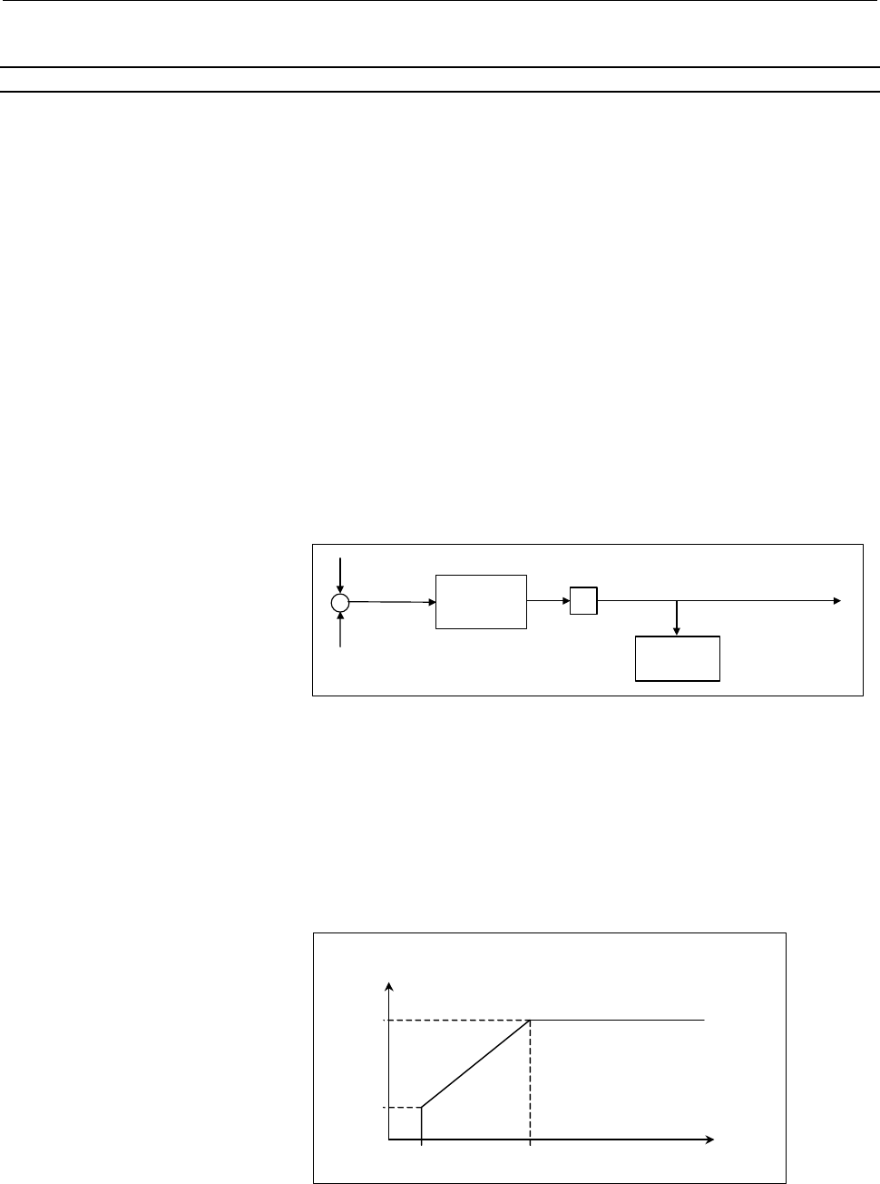
- Synchronization error compensation smooth suppress function
When bit 6 (SMS) of parameter No. 8304 is set to 1, the
synchronization error compensation smooth suppress function is
enabled. With this function, another set of parameters for a
synchronization error zero width and synchronization error
compensation gain (B and Ks in the figure below) can be set. So,
even a small synchronization error can be reduced smoothly as shown
below.
Synchronization error compensation gain
Synchronization error value
Kd
0
A
Ks
B
A: Synchronization error zero width (parameter No. 8333)
Contents Summary of 30i/300i/300is - Model A, 31i/310i/310is - Model A and A5, 32i/320i/320is - Model A Connection manual (Function)
- Page 1FANUC Series 30*-MODEL A FANUC Series 300*-MODEL A FANUC Series 300*s-MODEL A CONNECTION MANUAL (FUNCTION) B-63943EN-1/02
- Page 2• No part of this manual may be reproduced in any form. • All specifications and designs are subject to change without notice. The export of this product is subject to the authorization of the government of the country from where the product is exported. In this manual we have tried as much as possi
- Page 3B-63943EN-1/02 DEFINITION OF WARNING, CAUTION, AND NOTE DEFINITION OF WARNING, CAUTION, AND NOTE This manual includes safety precautions for protecting the user and preventing damage to the machine. Precautions are classified into Warning and Caution according to their bearing on safety. Also, suppl
- Page 4
- Page 5B-63943EN-1/02 PREFACE PREFACE Organization of this manual This manual describes all the NC functions required to enable machine tool builders to design their CNC machine tools. The following items are explained for each function. 1. Overview Describes feature of the function. Refer to Operator's ma
- Page 6PREFACE B-63943EN-1/02 NOTE 1 For an explanatory purpose, the following descriptions may be used according to the types of path control used: - T series: For the lathe system - M series: For the machining center system 2 Unless otherwise noted, the model names 31i/310i/310is-A, 31i/310i/310is-A5, an
- Page 7B-63943EN-1/02 PREFACE Description of symbols The following symbols are used in this manual. These symbols are described below. - M Indicates a description that is valid only for the machine center system set as system control type (in parameter No. 0983). In a general description of the method of m
- Page 8PREFACE B-63943EN-1/02 Description of signals [Example of controlling one path using one PMC] G0000~ X000~ CNC PMC Machine tool F0000~ Y000~ [Example of controlling three path using one PMC] CNC G0000~ X000~ Path 1 F0000~ Y000~ PMC Machine tool G1000~ Path 2 F1000~ G2000~ Path 3 F2000~ p-4
- Page 9B-63943EN-1/02 PREFACE [Example of controlling multipath CNC using PMC system] CNC Signal PMC I/F G0000~ G0000~ Path 1 X000~ F0000~ F0000~ Y000~ I/O device G1000~ G1000~ First for first PMC machine Path 2 F1000~ F1000~ First G2000~ G2000~ machine Path 3 group F2000~ F2000~ G3000~ G3000~ Path 4 F3000
- Page 10PREFACE B-63943EN-1/02 - Expression of signals Address Symbol (#0 to #7 indicates bit position) #7 #6 #5 #4 #3 #2 #1 #0 Fn000 OP SA STL SPL RWD In an item where both lathe system and machining center system are described, some signals are covered with shade ( ) in the signal address figure as shown
- Page 11B-63943EN-1/02 PREFACE Description of parameters Parameters are classified by data type as follows: Data type Valid data range Remarks Bit Bit machine group Bit path 0 or 1 Bit axis Bit spindle Byte Byte machine group Some parameters handle -128 to 127 Byte path these types of data as 0 to 255 Byte
- Page 12PREFACE B-63943EN-1/02 3.1 STANDARD PARAMETER SETTING TABLES This section defines the standard minimum data units and valid data ranges of the CNC parameters of the real type, real machine group type, real path type, real axis type, and real spindle type. The data type and unit of data of each param
- Page 13B-63943EN-1/02 PREFACE (C) Velocity and angular velocity parameters Increment Minimum Unit of data Valid data range system data unit IS-A 0.01 0.0 to +2400000.0 IS-B 0.001 0.0 to +240000.0 mm/min IS-C 0.0001 0.0 to +100000.0 degree/min IS-D 0.00001 0.0 to +10000.0 IS-E 0.000001 0.0 to +1000.0 IS-A 0
- Page 14PREFACE B-63943EN-1/02 - Parameters of the bit type, bit machine group type, bit path type, bit axis type, and bit spindle type #7 #6 #5 #4 #3 #2 #1 #0 0000 EIA NCR ISP CTV TVC Data No. Data (Data #0 to #7 are bit positions.) - Parameters other than the bit-type parameters above 1023 Number of the s
- Page 15B-63943EN-1/02 PREFACE Related manuals of Series 30i/300i/300is- MODEL A Series 31i/310i/310is- MODEL A Series 31i/310i/310is- MODEL A5 Series 32i/320i/320is- MODEL A The following table lists the manuals related to Series 30i/300i /300is-A, Series 31i/310i /310is-A, Series 31i/310i /310is-A5, Serie
- Page 16PREFACE B-63943EN-1/02 Related manuals of SERVO MOTOR αis/αi series The following table lists the manuals related to SERVO MOTOR αis/αi series Table 2 Related manuals Specification Manual name number FANUC AC SERVO MOTOR αis series FANUC AC SERVO MOTOR αi series B-65262EN DESCRIPTIONS FANUC AC SERVO
- Page 17B-63943EN-1/02 TABLE OF CONTENTS TABLE OF CONTENTS SAFETY PRECAUTIONS............................................................................s-1 PREFACE ....................................................................................................p-1 1 AXIS CONTROL.........................
- Page 18TABLE OF CONTENTS B-63943EN-1/02 1.4.2 Optional Command Multiplication.......................................................................113 1.4.3 Absolute Position Detection .................................................................................114 1.4.4 FSSB Setting .................
- Page 19B-63943EN-1/02 TABLE OF CONTENTS 2 PREPARATIONS FOR OPERATION ................................................. 324 2.1 EMERGENCY STOP................................................................................. 325 2.2 CNC READY SIGNALS ..........................................................
- Page 20TABLE OF CONTENTS B-63943EN-1/02 4.8 LINEAR SCALE WITH DISTANCE-CODED REFERENCE MARKS (SERIAL) ................................................................................................... 524 4.9 EXTENDED FUNCTION OF THE DISTANCE CODED LINEAR SCALE INTERFACE ..................................
- Page 21B-63943EN-1/02 TABLE OF CONTENTS 6.8 POLAR COORDINATE INTERPOLATION ................................................ 636 6.9 CYLINDRICAL INTERPOLATION ............................................................. 640 6.9.1 Cylindrical Interpolation ...................................................
- Page 22TABLE OF CONTENTS B-63943EN-1/02 7.1.11.2 Automatic feedrate control function ................................................................ 748 7.2 ACCELERATION/DECELERATION CONTROL........................................ 770 7.2.1 Automatic Acceleration/Deceleration .............................
- Page 23B-63943EN-1/02 TABLE OF CONTENTS 9.2 MANUAL FEED FOR 5-AXIS MACHINING ............................................. 1030 9.2.1 Tool Axis Direction Handle Feed/Tool Axis Direction JOG Feed/Tool Axis Direction Incremental Feed ...........................................................................
- Page 24TABLE OF CONTENTS B-63943EN-1/02 9.5.6 Alarm and Message ............................................................................................1159 9.6 TOOL DIRECTION THERMAL DISPLACEMENT COMPENSATION ..... 1161 10 AUXILIARY FUNCTION ............................................................
- Page 25B-63943EN-1/02 TABLE OF CONTENTS 11.11.13.3 Signals related to gear switching ........................................................ 1393 11.11.13.4 Signals related to the addition of multi spindle control...................... 1394 11.11.13.5 Notes on interface with the PMC ......................
- Page 26TABLE OF CONTENTS B-63943EN-1/02 12 TOOL FUNCTIONS ........................................................................... 1537 12.1 TOOL FUNCTIONS OF LATHE SYSTEM ............................................... 1538 12.1.1 Tool Offset ............................................................
- Page 27B-63943EN-1/02 TABLE OF CONTENTS 13.5.2 Indirect Axis Address Command .......................................................................1720 13.5.3 Interruption Type Custom Macro.......................................................................1722 13.6 CANNED CYCLE FOR DRILLING...........
- Page 28TABLE OF CONTENTS B-63943EN-1/02 16.4.1 Input of tool offset value measured ....................................................................1867 16.4.2 Input of Tool Offset Value Measured B.............................................................1869 16.5 TOOL LENGTH / WORKPIECE ZERO POINT M
- Page 29B-63943EN-1/02 1.AXIS CONTROL 1 AXIS CONTROL -1-
- Page 301.AXIS CONTROL B-63943EN-1/02 1.1 CONTROLLED AXIS Overview - Series 30i, Series 300i, Series 300is The maximum number of machine groups, maximum number of paths, maximum number of servo axes, and maximum number of spindles differ depending on the model, as listed in the table below. Series 30i-A Ser
- Page 31B-63943EN-1/02 1.AXIS CONTROL Reference item Manual name Item name USER’S MANUAL Number of controlled axes (B-63944EN) CONNECTION MANUAL Multipath control (FUNCTION) (This manual) -3-
- Page 321.AXIS CONTROL B-63943EN-1/02 1.2 SETTING EACH AXIS 1.2.1 Name of Axes Overview Each axis that is controlled by the CNC (including those controlled by the PMC) must be named. To name an axis, select a desired character from among A, B, C, U, V, W, X, Y, and Z and set the character as the first axis
- Page 33B-63943EN-1/02 1.AXIS CONTROL NOTE 1 If the second axis name character is not set for an axis, the third axis name character is invalid. 2 When setting 0 to 9 for the second axis name character, do not set A to Z for the third axis name character. 3 When an axis name ends with a numeric character, a
- Page 341.AXIS CONTROL B-63943EN-1/02 1020 Program axis name for each axis [Input type] Parameter input [Data type] Byte axis [Valid data range] 67,85 to 90 An axis name (axis name 1: parameter No. 1020) can be arbitrarily selected from 'A', 'B', 'C', 'U', 'V', 'W', 'X', 'Y', and 'Z'. (When G code system A
- Page 35B-63943EN-1/02 1.AXIS CONTROL 1025 Program axis name 2 for each axis 1026 Program axis name 3 for each axis [Input type] Parameter input [Data type] Byte axis [Valid data range] 48 to 57, 65 to 90 When axis name extension is enabled (when bit 0 (EEA) of parameter No. 1000 is set to 1), the length of
- Page 361.AXIS CONTROL B-63943EN-1/02 Example - Example of setting an axis name When No. 1020 = 88, No. 1025 = 0, and No. 1026 = 0, the axis name is set to X. When No. 1020 = 88, No. 1025 = 65, and No. 1026 = 0, the axis name is set to XA. When No. 1020 = 88, No. 1025 = 66, and No. 1026 = 65, the axis name
- Page 37B-63943EN-1/02 1.AXIS CONTROL 1.2.2 Increment System Overview The increment system consists of the least input increment (for input) and least command increment (for output). The least input increment is the least increment for programming the travel distance. The least command increment is the leas
- Page 381.AXIS CONTROL B-63943EN-1/02 Name of an Least input Least command Maximum stroke increment system increment increment 0.000001 mm 0.000001 mm ±999.999999 mm IS-E 0.0000001 inch 0.0000001 inch ±99.9999999 inch 0.000001 deg 0.000001 deg ±999.999999 deg When bit 7 (IPR) of parameter No. 1004, which mu
- Page 39B-63943EN-1/02 1.AXIS CONTROL #0 INM Least command increment on the linear axis 0: In mm (metric system machine) 1: In inches (inch system machine) #7 #6 #5 #4 #3 #2 #1 #0 1004 IPR [Input type] Parameter input [Data type] Bit path #7 IPR When a number with no decimal point is specified, the least in
- Page 401.AXIS CONTROL B-63943EN-1/02 #0 ISA #1 ISC #2 ISD #3 ISE Increment system of each axis Increment system #3 ISE #2 ISD #1 ISC #0 ISA IS-A 0 0 0 1 IS-B 0 0 0 0 IS-C 0 0 1 0 IS-D 0 1 0 0 IS-E 1 0 0 0 Reference item Manual name Item name USER’S MANUAL Increment system (B-63944EN) - 12 -
- Page 41B-63943EN-1/02 1.AXIS CONTROL 1.2.3 Diameter and Radius Setting Switching Function Overview Usually, whether to use diameter specification or radius specification to specify a travel distance on each axis is uniquely determined by the setting of bit 3 (DIAx) of parameter No. 1006. However, this func
- Page 421.AXIS CONTROL B-63943EN-1/02 NOTE 1 When operating an input signal by using an M code, for example, during automatic operation, perform a switching operation according to the method below to reflect the state of diameter/radius specification switching in the execution block correctly. As an auxilia
- Page 43B-63943EN-1/02 1.AXIS CONTROL - Switching operation According to the switching methods above, diameter/radius specification is internally switched as described below. 1) Switching using a signal - When parameter DIAx = 0 (radius specification) → Operation is performed with diameter specification. -
- Page 441.AXIS CONTROL B-63943EN-1/02 Signal address #7 #6 #5 #4 #3 #2 #1 #0 Gn296 DI8 DI7 DI6 DI5 DI4 DI3 DI2 DI1 Fn296 DM8 DM7 DM6 DM5 DM4 DM3 DM2 DM1 Parameter #7 #6 #5 #4 #3 #2 #1 #0 3400 PGD [Input type] Parameter input [Data type] Bit path #5 PGD Specification of G10.9 specification (programmable diam
- Page 45B-63943EN-1/02 1.AXIS CONTROL Limitation - Feedrate A radius-based feedrate is specified in both of diameter specification and radius specification at all times. - Data not switchable The following data follows the setting of parameter DIAx, so that diameter/radius specification switching is not per
- Page 461.AXIS CONTROL B-63943EN-1/02 Caution CAUTION When switching is performed from diameter specification to radius specification, the travel distance based on the same move command is doubled when compared with diameter specification. So, when switching from diameter specification to radius specificati
- Page 47B-63943EN-1/02 1.AXIS CONTROL 1.2.4 Specifying the Rotation Axis Overview Parameter ROTx (No.1006#0) can be used to set each axis to a linear axis or rotation axis. Parameter ROSx (No. 1006#1) can be used to select the rotation axis type, A or B, for each axis. See the explanation of the parameters
- Page 481.AXIS CONTROL B-63943EN-1/02 ROTx, ROSx Setting linear or rotation axis. ROSx ROTx Meaning 0 0 Linear axis (1) Inch/metric conversion is done. (2) All coordinate values are linear axis type. (Is not rounded in 0 to 360_) (3) Stored pitch error compensation is linear axis type (Refer to parameter No
- Page 49B-63943EN-1/02 1.AXIS CONTROL NOTE 1 RRLx is valid only when ROAx is 1. 2 Assign the amount of the shift per one rotation in parameter No.1260. 1260 Amount of a shift per one rotation of a rotation axis NOTE When this parameter is set, the power must be turned off before operation is continued. [Inp
- Page 501.AXIS CONTROL B-63943EN-1/02 1.2.5 Controlled Axes Detach Overview These signals release the specified control axes from control by the CNC. When attachments are used (such as a detachable rotary table), these signals are selected according to whether the attachments are mounted. When multiple rota
- Page 51B-63943EN-1/02 1.AXIS CONTROL Signal address #7 #6 #5 #4 #3 #2 #1 #0 Gn124 DTCH8 DTCH7 DTCH6 DTCH5 DTCH4 DTCH3 DTCH2 DTCH1 #7 #6 #5 #4 #3 #2 #1 #0 Fn110 MDTCH8 MDTCH7 MDTCH6 MDTCH5 MDTCH4 MDTCH3 MDTCH2 MDTCH1 Parameter #7 #6 #5 #4 #3 #2 #1 #0 0012 RMVx [Input type] Setting input [Data type] Bit axis
- Page 521.AXIS CONTROL B-63943EN-1/02 Caution CAUTION When a multiaxis amplifier is used, the motor cannot be disconnected from the amplifier. When the motor needs to be disconnected from the amplifier for replacement of the rotary table or other reasons, a 1-axis amplifier must be used. Note NOTE 1 Control
- Page 53B-63943EN-1/02 1.AXIS CONTROL 1.2.6 Outputting the Movement State of an Axis Overview The movement state of each axis can be output to the PMC. Signal Axis moving signals MV1 to MV8
[Classification] Output signal [Function] These signals indicate that a control axis is moving. The signals are - Page 541.AXIS CONTROL B-63943EN-1/02 CAUTION CAUTION Axis moving signals and axis moving direction signals are output in both automatic and manual operations. - 26 -
- Page 55B-63943EN-1/02 1.AXIS CONTROL 1.2.7 Mirror Image Overview Mirror image can be applied to each axis, either by signals or by parameters (setting input is acceptable). All movement directions are reversed during automatic operation along axes to which a mirror image is applied. X B A B’f Z 0 When MI1
- Page 561.AXIS CONTROL B-63943EN-1/02 Mirror image check signals MMI1 to MMI8
[Classification] Output signal [Function] These signals indicate the mirror image condition of each axis. The mirror image is set by taking the logical sum of the signal from the MDI panel and the input signal of the machin - Page 57B-63943EN-1/02 1.AXIS CONTROL CAUTION CAUTION Even when the mirror image is applied, commands which do not actuate mirror image (such as automatic reference position return and manual operation) do not affect mirror image check signals MMI1 to MMI8
. Reference item Manual name Item name USER’S - Page 581.AXIS CONTROL B-63943EN-1/02 1.2.8 Follow-up Overview If the machine moves in the state in which position control on controlled axes is disabled (during servo-off, emergency stop, or servo alarm), feedback pulses are accumulated in the error counter. The CNC reflects the machine movement correspond
- Page 59B-63943EN-1/02 1.AXIS CONTROL Parameter #7 #6 #5 #4 #3 #2 #1 #0 1819 FUPx [Input type] Parameter input [Data type] Bit axis #0 FUPx To perform follow-up when the servo is off is set for each axis. 0: The follow-up signal, *FLWU, determines whether follow-up is performed or not. When *FLWU is 0, foll
- Page 601.AXIS CONTROL B-63943EN-1/02 1.2.9 Servo off/Mechanical Handle Feed Overview Place the controlled axes in the servo off state, stop the current to the servo motor, which disables position control. However, the position detection feature functions continuously, so the current position is not lost. T
- Page 61B-63943EN-1/02 1.AXIS CONTROL Caution CAUTION 1 In general, interlock is applied to an axis while the servo off signal for that axis is 1. 2 When one of these signals turns to "1", the servo motor is turned off. The mechanical clamp is done by using the auxiliary function. Set the timing for the aux
- Page 621.AXIS CONTROL B-63943EN-1/02 1.2.10 Position Switch Overview Position switch signals can be output to the PMC while the machine coordinates along a controlled axes are within a specified ranges. Using parameters, specify arbitrary controlled axes and machine coordinate operating ranges for which po
- Page 63B-63943EN-1/02 1.AXIS CONTROL Parameter #7 #6 #5 #4 #3 #2 #1 #0 6901 PSA EPW [Input type] Parameter input [Data type] Bit path #1 EPW The number of position switches is: 0: Not extended. 1: Extended. #2 PSA In determination of a position switch function operation range, a servo delay amount (positio
- Page 641.AXIS CONTROL B-63943EN-1/02 6930 Maximum value of the operating range of the 1-st position switch (PSW101) to 6945 Maximum value of the operating range of the 16-th position switch (PSW116) [Input type] Parameter input [Data type] Real path [Unit of data] mm, inch, degree (machine unit) [Minimum u
- Page 65B-63943EN-1/02 1.AXIS CONTROL 1.2.11 High-Speed Position Switch Overview The high-speed position switch function monitors the current position at shorter intervals than the normal position switch function to output a high-speed precise position switch signal. In the same way as for the normal positi
- Page 661.AXIS CONTROL B-63943EN-1/02 Signal address #7 #6 #5 #4 #3 #2 #1 #0 Yxxx HPS08 HPS07 HPS06 HPS05 HPS04 HPS03 HPS02 HPS01 Yxxx+1 HPS16 HPS15 HPS14 HPS13 HPS12 HPS11 HPS10 HPS09 xxx indicates the address set using parameter No. 8565. When bit 0 (HPF) of parameter No. 8501 is set to 1, the signal addr
- Page 67B-63943EN-1/02 1.AXIS CONTROL 8565 Output address of the high-speed position switch signal NOTE When this parameter is set, the power must be turned off before operation is continued. [Input type] Parameter input [Data type] Word path [Valid data range] 0 to 126 This parameter sets a Y signal addres
- Page 681.AXIS CONTROL B-63943EN-1/02 Controlled axis for which the first high-speed position switch function is 8570 performed to Controlled axis for which the tenth high-speed position switch function is 8579 performed Controlled axis for which the eleventh high-speed position switch function is 12201 per
- Page 69B-63943EN-1/02 1.AXIS CONTROL NOTE Parameters No. 8586 to 8589 and No. 12221 to 12226 are valid only when EHP (bit 7 of parameter No. 8500) is 1. 8590 Minimum value of the operation range of the first high-speed position switch to Minimum value of the operation range of the tenth high-speed position
- Page 701.AXIS CONTROL B-63943EN-1/02 1.2.12 Direction-Sensitive High-Speed Position Switch Overview The high-speed position switch function monitors the machine coordinates and move direction to output high-speed position switch signals. Two machine coordinates are monitored. When the tool passes through o
- Page 71B-63943EN-1/02 1.AXIS CONTROL Fig. 1.2.12 (a) shows the output status of a direction-sensitive high-speed position switch signal when the current position moves from a to b, c, d, e, f, and g. The direction-sensitive high-speed position switch signal is assumed to be set as follows: - 1 when the too
- Page 721.AXIS CONTROL B-63943EN-1/02 Relationships between direction-sensitive high-speed position switches and output addresses Output Maximum Effective Minimum Effective Output signal Controlled-axi Enable/ type operating direction operating direction address s number disable switching range for point A
- Page 73B-63943EN-1/02 1.AXIS CONTROL #7 #6 #5 #4 #3 #2 #1 #0 8508 D08 D07 D06 D05 D04 D03 D02 D01 8509 D16 D15 D14 D13 D12 D11 D10 D09 [Input type] Parameter input [Data type] Bit path NOTE When this parameter is set, the power must be turned off before operation is continued. D01 to D16 The output type of
- Page 741.AXIS CONTROL B-63943EN-1/02 CAUTION 1 Specifying a nonexistent signal address causes the high-speed position switch function to be disabled. 2 Y signal address Y127 cannot be specified for this function. 3 Address output signals (Y1001 and above) on the M-NET board cannot be specified for this fun
- Page 75B-63943EN-1/02 1.AXIS CONTROL 1.3 ERROR COMPENSATION 1.3.1 Stored Pitch Error Compensation Overview If pitch error compensation data is specified, pitch errors of each axis can be compensated in detection units per axis. Pitch error compensation data is set for each compensation position at the inte
- Page 761.AXIS CONTROL B-63943EN-1/02 Explanation - Specifying the compensation position To assign the compensation positions for each axis, specify the positive direction or the negative direction relative to the compensation position No. of the reference position. If the machine stroke exceeds the specifi
- Page 77B-63943EN-1/02 1.AXIS CONTROL No. of the compensation position of the reference position + (Machine stroke on the positive side/Interval between the compensation positions)= 40 + 800/50= 56 The correspondence between the machine coordinate and the compensation position No. is as follows: -400 -350 -
- Page 781.AXIS CONTROL B-63943EN-1/02 The No. of the farthest compensation position in the positive direction is as follows: No. of the compensation position of the reference position + (Move amount per rotation/Interval between the compensation positions)= 60 + 360/45= 68 The correspondence between the mac
- Page 79B-63943EN-1/02 1.AXIS CONTROL Number 60 61 62 63 64 65 66 67 68 Compensation value +1 -2 +1 +3 -1 -1 -3 +2 +1 Pitch error +4 compensation value (absolute value) +3 Reference position 68 +2 (60) +1 68 61 62 63 64 65 66 67 61 62 63 64 65 66 67 (60)61 62 45 90135180225270315 0 45 90135180225270315 0 45
- Page 801.AXIS CONTROL B-63943EN-1/02 Number of the pitch error compensation position at extremely positive 3622 position for each axis NOTE When this parameter is set, the power must be turned off before operation is continued. [Input type] Parameter input [Data type] Word axis [Valid data range] 0 to 1535
- Page 81B-63943EN-1/02 1.AXIS CONTROL Travel distance per revolution in pitch error compensation of rotation axis 3625 type NOTE When this parameter is set, the power must be turned off before operation is continued. [Input type] Parameter input [Data type] Real axis [Unit of data] mm, inch, degree (machine
- Page 821.AXIS CONTROL B-63943EN-1/02 Warning WARNING - Compensation value range Compensation values can be set within the range from -127 × compensation magnification (detection unit) to +127 × compensation magnification (detection unit). The compensation magnification can be set for each axis within the r
- Page 83B-63943EN-1/02 1.AXIS CONTROL 1.3.2 Backlash Compensation Overview - Backlash compensation Function for compensating for lost motion on the machine. Set a compensation value in parameter No. 1851, in detection units from 0 to ±9999 pulses for each axis. - Backlash compensation for each rapid travers
- Page 841.AXIS CONTROL B-63943EN-1/02 Parameter #7 #6 #5 #4 #3 #2 #1 #0 1800 RBK [Input type] Parameter input [Data type] Bit path #4 RBK Backlash compensation applied separately for cutting feed and rapid traverse 0: Not performed 1: Performed 1851 Backlash compensating value for each axis [Input type] Par
- Page 85B-63943EN-1/02 1.AXIS CONTROL Caution CAUTION The backlash compensation for rapid traverse and cutting feed is not performed until the first reference position return is completed after the power is turned on. Under this state, the normal backlash compensation is performed according to the value spe
- Page 861.AXIS CONTROL B-63943EN-1/02 1.3.3 Smooth Backlash Explanation With normal backlash compensation, all backlash compensation pulses are output at the location where the direction of axis moving reverses. (Fig. 1.3.3 (a)) (Direction reverse) Direction of axis moving Total amount of backlash compensat
- Page 87B-63943EN-1/02 1.AXIS CONTROL ・First stage backlash compensation output At the location where the direction of axis moving reverses, the first stage backlash compensation output is performed. Set the first stage backlash compensation B1, using parameter No. No.1848. ・Second stage backlash compensati
- Page 881.AXIS CONTROL B-63943EN-1/02 Parameter #7 #6 #5 #4 #3 #2 #1 #0 1817 SBL [Data type] Bit axis NOTE When this parameter is set, the power must be turned off before operation is continued. #2 SBL Smooth backlash compensation is : 0: Disabled. 1: Enabled. 1846 Distance for starting the second stage of
- Page 89B-63943EN-1/02 1.AXIS CONTROL 1848 Value of the first stage of smooth backlash compensation NOTE When this parameter is set, the power must be turned off before operation is continued. [Data type] Word axis [Unit of data] Detection unit [Valid data range] -9999 to 9999 Set the value of the first sta
- Page 901.AXIS CONTROL B-63943EN-1/02 1.3.4 Straightness Compensation Overview For a machine tool with a long stroke, deviations in straightness between axes may affect the machining accuracy. For this reason, when an axis moves, other axes are compensated in detection units to improve straightness. This im
- Page 91B-63943EN-1/02 1.AXIS CONTROL - Example Imagine a table whose Y-axis ball screw is placed on its X-axis ball screw. If the X-axis ball screw is inclined at a certain angle because of, for example, bending, the machining precision related to the Y-axis becomes low because its ball screw is affected b
- Page 921.AXIS CONTROL B-63943EN-1/02 [Data type] Byte path [Valid data range] 0 to Number of controlled axes Set the axis numbers of moving axes for straightness compensation. When 0 is set, compensation is not performed. Straightness compensation : 5721 Axis number of compensation axis 1 for moving axis 1
- Page 93B-63943EN-1/02 1.AXIS CONTROL Straightness compensation : 13324 Compensation point number d of moving axis 6 NOTE When this parameter is set, the power must be turned off before operation is continued. [Input type] Parameter input [Data type] Word path [Valid data range] 0 to 1535 Compensation corre
- Page 941.AXIS CONTROL B-63943EN-1/02 Alarm and message Number Message Description PW1103 ILLEGAL PARAMETER (S-COMP.128) The parameter for setting 128 straightness compensation points or the parameter compensation data is incorrect, PW5046 ILLEGAL PARAMETER (S-COMP.) The parameter for setting straightness c
- Page 95B-63943EN-1/02 1.AXIS CONTROL 1.3.5 Straightness Compensation at 128 Points Overview In straightness compensation, this function sets compensation data as the compensations at individual compensation points in the same way as in stored pitch error compensation. This enables fine compensation to be a
- Page 961.AXIS CONTROL B-63943EN-1/02 φ Number of the furthest straightness compensation point in the negative region on the moving axis Parameters Nos. 13381 to No.13386 π Number of the furthest straightness compensation point in the positive region on the moving axis δ Straightness compensation point numb
- Page 97B-63943EN-1/02 1.AXIS CONTROL Parameter setting examples The following explains how to set the parameters for moving and compensation axes, as well as effective magnifications. The parameters for moving and compensation axes can be set as described below. <1> A single compensation axis can be set fo
- Page 981.AXIS CONTROL B-63943EN-1/02 1.3.6 Interpolated Straightness Compensation Overview This function divides the compensation data established using the compensation data for straightness compensation at 128 points among compensation points and outputs the resulting data. Explanation - Compensation sys
- Page 99B-63943EN-1/02 1.AXIS CONTROL Parameter #7 #6 #5 #4 #3 #2 #1 #0 3605 IPC [Input type] Parameter input [Data type] Bit axis NOTE When this parameter is set, the power must be turned off before operation is continued. #2 IPC Interpolated straightness compensation function is: 0: Not used. 1: Used. 571
- Page 1001.AXIS CONTROL B-63943EN-1/02 Straightness compensation : 5725 Axis number of compensation axis 5 for moving axis 5 Straightness compensation : 5726 Axis number of compensation axis 6 for moving axis 6 NOTE When this parameter is set, the power must be turned off before operation is continued. [Inpu
- Page 101B-63943EN-1/02 1.AXIS CONTROL 13391 Magnification for straightness compensation for moving axis 1 13392 Magnification for straightness compensation for moving axis 2 13393 Magnification for straightness compensation for moving axis 3 13394 Magnification for straightness compensation for moving axis
- Page 1021.AXIS CONTROL B-63943EN-1/02 CAUTION CAUTION 1 Straightness compensation at 128 points and interpolated straightness compensation are both optional functions. 2 If the options, straightness compensation at 128 points and interpolated straightness compensation, are to be attached, the option, stored
- Page 103B-63943EN-1/02 1.AXIS CONTROL 1.3.7 Gradient Compensation Overview By compensating for those errors in tools such as feed screws that depend on the position of the machine system in detection units, machining precision can be improved and mechanical life can be prolonged. Compensation is performed a
- Page 1041.AXIS CONTROL B-63943EN-1/02 In above figure, the compensation amounts at the individual compensation points located between points a and b are (β-α)/(b-a). Parameter 5861 Inclination compensation : Compensation point number a for each axis 5862 Inclination compensation : Compensation point number
- Page 105B-63943EN-1/02 1.AXIS CONTROL Alarm and message Number Message Description PW1102 ILLEGAL PARAMETER (I-COMP.) The parameter for setting slope compensation is incorrect. This alarm occurs in the following cases: - When the number of pitch error compensation points on the axis on which slope compensat
- Page 1061.AXIS CONTROL B-63943EN-1/02 1.3.8 Bi-directional Pitch Error Compensation Overview In bi-directional pitch error compensation, different pitch error compensation amounts can be set for travel in the positive direction and that in the negative direction, so that pitch error compensation can be perf
- Page 107B-63943EN-1/02 1.AXIS CONTROL 2. Pitch error compensation data The compensation point numbers can be from 0 to 1535 and from 3000 to 4535. This data may be used for both the positive and negative directions. Note, however, that the set of compensation data for a given axis cannot extend over 1535 an
- Page 1081.AXIS CONTROL B-63943EN-1/02 Table 1.3.8 (b) Positive-direction pitch error data Compensation 20 21 22 23 24 25 26 27 point number Compensation -1 +1 0 +1 +1 +2 -1 -1 amount to be set As pitch error data, always set incremental values as viewed in the negative direction (direction toward the left i
- Page 109B-63943EN-1/02 1.AXIS CONTROL - Compensation example If, in the setting example given in the previous section, the machine moves 0.0 to 40.0, 40.0 to -40.0, and -40.0 to 0.0 for a manual reference position return, pitch error compensation pulses are output as follows: Machine 0.0 5.0 15.0 25.0 35.0
- Page 1101.AXIS CONTROL B-63943EN-1/02 - Setting and displaying data All the compensation data can be displayed and set on the conventional screen for the pitch error compensation data. And those data can be input and output by the following methods. - Input by MDI - Input by G10 - Input and output by input/
- Page 111B-63943EN-1/02 1.AXIS CONTROL Number of the pitch error compensation position at extremely negative 3621 position for each axis NOTE When this parameter is set, the power must be turned off before operation is continued. [Input type] Parameter input [Data type] Word axis [Valid data range] 0 to 1535
- Page 1121.AXIS CONTROL B-63943EN-1/02 3624 Interval between pitch error compensation positions for each axis NOTE When this parameter is set, the power must be turned off before operation is continued. [Input type] Parameter input [Data type] Real axis [Unit of data] mm, inch, degree (machine unit) [Minimum
- Page 113B-63943EN-1/02 1.AXIS CONTROL Number of the both-direction pitch error compensation position at extremely 3626 negative position (for movement in the negative direction) NOTE When this parameter is set, the power must be turned off before operation is continued. [Input type] Parameter input [Data ty
- Page 1141.AXIS CONTROL B-63943EN-1/02 Note NOTE 1 To use this function, the stored pitch error compensation option is required. 2 This function is enabled after a manual reference position return or an automatic reference position return with the same sequence as that of a manual reference position return i
- Page 115B-63943EN-1/02 1.AXIS CONTROL 1.3.9 Extended Bi-directional Pitch Error Compensation Overview In bi-directional pitch error compensation, it is possible to use 0 - 1535, 3000 - 4535 points as the compensation points. By using this function, the compensation points are extended and it is possible to
- Page 1161.AXIS CONTROL B-63943EN-1/02 Set the number of the pitch error compensation position at the extremely negative position for each axis. Number of the pitch error compensation position at extremely positive 3622 position for each axis NOTE When this parameter is set, the power must be turned off befo
- Page 117B-63943EN-1/02 1.AXIS CONTROL 1.3.10 Interpolation Type Pitch Error Compensation Overview In stored pitch error compensation, the pitch error compensation pulse at each pitch error compensation point is output in the interval between that point and the next compensation point, as shown in the figure
- Page 1181.AXIS CONTROL B-63943EN-1/02 - Setting the parameters When interpolation type pitch error compensation is used, the following parameters are assigned the same values as those in stored pitch error compensation. - Number of the pitch error compensation point of the reference position on each axis (N
- Page 119B-63943EN-1/02 1.AXIS CONTROL A minimum interval where multiple compensation pulses are not output at a time is determined by the following expression: Minimum pitch error compensation point interval = (Fmax/7500) × (Pmax+1) Fmax: Maximum feedrate Pmax: Maximum pitch error compensation value Example
- Page 1201.AXIS CONTROL B-63943EN-1/02 1.3.11 About Differences among Pitch Error Compensation, Straightness Compensation, and Gradient Compensation (for Reference Purposes) Overview Any of pitch error compensation, straightness compensation, and gradient compensation is applied to each compensation point ba
- Page 121B-63943EN-1/02 1.AXIS CONTROL b c a d - Straightness compensation In straightness compensation, similarly to gradient compensation, four typical pitch error compensation points (a, b, c, and d) are selected from pitch error compensation points and specified as straightness compensation points, and c
- Page 1221.AXIS CONTROL B-63943EN-1/02 1.3.12 Cyclic Second Pitch Error Compensation Overview When a rotary table is rotated using a gear, there are two cycles of the occurrence of pitch errors: One cycle is the same as that of the rotation of the rotary table while the other is the same as that of the rotat
- Page 123B-63943EN-1/02 1.AXIS CONTROL Although a rotary table is used as an example here, cyclic second pitch error compensation can be used in the same way when the machine is moved along a linear axis using a gear. For example, in a configuration such as that shown in Fig. 1.3.9 (c), stored pitch error co
- Page 1241.AXIS CONTROL B-63943EN-1/02 - Pitch error with a 360° cycle 180° ε A 0° 360° 20° Fig. 1.3.12 (e) - Pitch error after superimposition in portion A Pitch error with the cycle of the rotation of the gear ε : Pitch error in portion A ε A Fig. 1.3.12 (f) Synchronous Second Pitch Error The above figure
- Page 125B-63943EN-1/02 1.AXIS CONTROL Parameter Number of the farthest second cyclical pitch error compensation point in the 14985 negative direction for each axis NOTE When this parameter is set, the power must be turned off before operation is continued. [Input type] Parameter input [Data type] Word axis
- Page 1261.AXIS CONTROL B-63943EN-1/02 14988 Magnification for second cyclical pitch error compensation for each axis NOTE When this parameter is set, the power must be turned off before operation is continued. [Input type] Parameter input [Data type] Byte axis [Valid data range] 0 to 100 Set a magnification
- Page 127B-63943EN-1/02 1.AXIS CONTROL 1.3.13 Three-Dimensional Error Compensation Outline In ordinary pitch error compensation, compensation is applied to a specified compensation axis (single axis) by using its position information. For example, pitch error compensation is applied to X-axis by using the po
- Page 1281.AXIS CONTROL B-63943EN-1/02 P1x and P2x are the X coordinates of P1 and P2. The interior division ratios on Y and Z-axes are determined in the same way. The compensation amount Cx for X-axis at P is determined as Cx = C1x × (1 − x) × (1 − y ) × (1 − z ) + C 2 x × x × (1 − y ) × (1 − z ) + C 3x × x
- Page 129B-63943EN-1/02 1.AXIS CONTROL Parameters st 10800 Axis for which three-dimensional error compensation is performed (1 axis) nd 10801 Axis for which three-dimensional error compensation is performed (2 axis) rd 10802 Axis for which three-dimensional error compensation is performed (3 axis) NOTE When
- Page 1301.AXIS CONTROL B-63943EN-1/02 [Valid data range] From 1 through the number of the compensation points. Set three-dimensional error compensation point number at the reference position st 10809 Magnification for three-dimensional error compensation (1 axis) nd 10810 Magnification for three-dimensional
- Page 131B-63943EN-1/02 1.AXIS CONTROL Note NOTE 1 The controlled axis on which three-dimensional error compensation is to be applied must be a linear axis. 2 Three-dimensional error compensation cannot be performed until a reference position return is performed for the compensation axis. 4 The reference pos
- Page 1321.AXIS CONTROL B-63943EN-1/02 1.4 SETTINGS RELATED TO SERVO-CONTROLLED AXES The servo interface of the Series 16 features the following: • Digitally controlled AC servo motor • Motor feedback with serial pulse coders (1) Absolute pulse coder with a resolution of 1,000,000 pulses/rev (2) Absolute pul
- Page 133B-63943EN-1/02 1.AXIS CONTROL 1.4.1 Parameters Related to Servo Overview Terms frequently used in explanation of parameters related to servo systems are listed below: Least command increment The minimum unit of a command to be given from CNC to the machine tool Detection unit The minimum unit which
- Page 1341.AXIS CONTROL B-63943EN-1/02 #7 #6 #5 #4 #3 #2 #1 #0 1815 APCx APZx OPTx [Input type] Parameter input [Data type] Bit axis NOTE When this parameter is set, the power must be turned off before operation is continued. #1 OPTx Position detector 0: A separate pulse coder is not used. 1: A separate puls
- Page 135B-63943EN-1/02 1.AXIS CONTROL #7 #6 #5 #4 #3 #2 #1 #0 1816 DM3x DM2x DM1x [Input type] Parameter input [Data type] Bit axis NOTE When this parameter is set, the power must be turned off before operation is continued. #4 DM1 #5 DM2 #6 DM3 By using DM1, DM2, and DM3, a detection multiplication factor
- Page 1361.AXIS CONTROL B-63943EN-1/02 (1) T series Least command Least input increment increment Millimeter 0.001 mm (diameter specification) 0.0005 mm Millimeter input 0.001 mm (radius specification) 0.001 mm machine 0.0001 inch (diameter specification) 0.0005 mm Inch input 0.0001 inch (radius specificatio
- Page 137B-63943EN-1/02 1.AXIS CONTROL (2) M series Increment Least input increment and least command increment system IS-A IS-B IS-C IS-D IS-E Unit Millimeter 0.01 0.001 0.0001 0.00001 0.000001 mm machine Millimeter 0.001 0.0001 0.00001 0.000001 0.0000001 inch input Rotation 0.01 0.001 0.0001 0.00001 0.0000
- Page 1381.AXIS CONTROL B-63943EN-1/02 NOTE If a feedrate exceeding the feedrate found by the expression below is used, an incorrect travel amount may result or a servo alarm may be issued. Be sure to use a feedrate not exceeding the feedrate found by the following expression: Fmax[mm/min] = 196602 × 104 × l
- Page 139B-63943EN-1/02 1.AXIS CONTROL 1828 Positioning deviation limit for each axis in movement [Input type] Parameter input [Data type] 2-word axis [Unit of data] Detection unit [Valid data range] 0 to 99999999 Set the positioning deviation limit in movement for each axis. If the positioning deviation exc
- Page 1401.AXIS CONTROL B-63943EN-1/02 Generally, set the middle value between the positioning deviation limit during movement and the positioning deviation at rapid traverse as the feed stop positioning deviation. 1850 Grid shift and reference position shift for each axis NOTE When this parameter is set, th
- Page 141B-63943EN-1/02 1.AXIS CONTROL 1.4.2 Optional Command Multiplication Overview If the detection unit becomes a special value, an optional command multiplication can be set with an n:m ratio. The valid data range is between 1/9999 to 9999/1. Explanation - Optional command multiplication If the detectio
- Page 1421.AXIS CONTROL B-63943EN-1/02 1.4.3 Absolute Position Detection Overview An absolute position detector (absolute pulse coder) is an incremental pulse coder with an absolute counter. It detects the absolute position based on the value of the absolute counter. For an axis on which an absolute position
- Page 143B-63943EN-1/02 1.AXIS CONTROL - Manual reference position return Follow the procedure below to perform manual reference position return. (1) Set bit 4 (APZ) of parameter No. 1815 to 0. Alarms (PW0000) and (DS0300) are displayed. (2) Turn the power off, then on again. Alarm (DS0300) is displayed. (3)
- Page 1441.AXIS CONTROL B-63943EN-1/02 [Operation] These signals are 1 in the following case: - The batteries for the absolute position detector have run out. The batteries need be replaced in the status in which the power to the machine is on. These signals are 0 in the following case: - The batteries for t
- Page 145B-63943EN-1/02 1.AXIS CONTROL Parameter #7 #6 #5 #4 #3 #2 #1 #0 1803 NFP [Input type] Parameter input [Data type] Bit path #7 NFP If position matching between the machine position and absolute position detector is not performed even once, follow-up operation is: 0: Not performed. 1: Performed. #7 #6
- Page 1461.AXIS CONTROL B-63943EN-1/02 #7 #6 #5 #4 #3 #2 #1 #0 1819 CRFx [Input type] Parameter input [Data type] Bit axis #1 CRFx When the servo alarm SV0445 (soft disconnection), SV0447 (hard disconnection (separate)), or SV0421 (dual position feedback excessive error) is issued: 0: The reference position
- Page 147B-63943EN-1/02 1.AXIS CONTROL Number Message Description SV0301 APC ALARM: COMMUNICATION Since the absolute-position detector caused a communication ERROR error, the correct machine position could not be obtained. (data transfer error) The absolute-position detector, cable, or servo interface module
- Page 1481.AXIS CONTROL B-63943EN-1/02 Caution CAUTION The normal voltage of the backup batteries for an absolute pulse coder is 6 V. The voltage drops as time goes by. 6V 4.5V PBATL 1.5V PBATZ PBATL: Battery voltage low alarm This alarm is output when the voltage becomes 4.5 V or less. When this alarm is ou
- Page 149B-63943EN-1/02 1.AXIS CONTROL Note NOTE 1 For an absolute position detector, batteries are used because the absolute position must be retained. When the battery voltage becomes low, a battery low alarm for the absolute position detector is displayed on the machine's operator panel or screen. If a ba
- Page 1501.AXIS CONTROL B-63943EN-1/02 1.4.4 FSSB Setting Overview Connecting the CNC control section to servo amplifiers via a high-speed serial bus (FANUC Serial Servo Bus, or FSSB), which uses only one fiber optics cable, can significantly reduce the amount of cabling in machine tool electrical sections.
- Page 151B-63943EN-1/02 1.AXIS CONTROL CNC Controlled Program Slave axis axis name No. number (No. 1020) Single-axis 1 1 X amplifier 2 Y Two-axis 2 amplifier 3 Z 3 4 A Two-axis 4 5 B amplifier 5 6 C M1 6 Single-axis 7 amplifier M2 8 M1/M2: First/second separate detector interface unit - Manual setting 1 The
- Page 1521.AXIS CONTROL B-63943EN-1/02 • No number can be skipped in parameter No. 1023; for example, servo axis number 3 cannot be used for any axis unless servo axis number 2 is used. • The following servo functions cannot be used: - High-speed current loop - Tandem control - Electric gear box (EGB) - Auto
- Page 153B-63943EN-1/02 1.AXIS CONTROL - Manual setting 2 After parameter FMD (No. 1902#0) is set to 1 or automatic setting has been terminated (ASE (No. 1902#1) is set to 1), manual setting 2 for each parameter for axis setting can be performed. To perform manual setting 2, set parameter Nos. 1023, 1905, 19
- Page 1541.AXIS CONTROL B-63943EN-1/02 No. 14376 14377 14378 14379 14380 14381 14382 14383 0 4 32 32 32 32 32 32 No. 14384 14385 14386 14387 14388 14389 14390 14391 3 2 5 32 32 32 32 32 No. 14392 to 14407 - - For servo HRV3 control When servo HRV3 control is used, specify numbers other than a multiple of 4 i
- Page 155B-63943EN-1/02 1.AXIS CONTROL - For servo HRV4 control When servo HRV4 control is used, specify odd numbers in parameter No. 1023 as servo axis numbers. Also set bit 1 (2AX) of parameter No. 14476 to 1 to use the servo software 90Dx series for servo HRV4 control. CNC FSSB Line1 Controlled Program Se
- Page 1561.AXIS CONTROL B-63943EN-1/02 FSSB display and setting procedure - Display The FSSB setting screen displays FSSB-based amplifier and axis information. This information can also be specified by the operator. 1 Press the SYSTEM function key. 2 To display [FSSB], press the next menu page key several ti
- Page 157B-63943EN-1/02 1.AXIS CONTROL The amplifier setting screen consists of the following items: • NO. : Slave number For each FSSB line, the serial numbers assigned to up to 18 slaves (up to 16 amplifiers and up to 2 separate detector interface units) connected by the FSSB are displayed. Number 1 is ass
- Page 1581.AXIS CONTROL B-63943EN-1/02 1026 are also displayed. If the controlled axis number is 0, - is displayed. • The following items are displayed as amplifier information: - UNIT : Servo amplifier unit type - SERIES : Servo amplifier series - CUR. : Maximum rating current • The following items are disp
- Page 159B-63943EN-1/02 1.AXIS CONTROL • M2:Connector number for separate detector interface unit 2 The connector number for separate detector interface unit 2 that is retained in the SRAM is displayed. • M3:Connector number for separate detector interface unit 3 The connector number for separate detector in
- Page 1601.AXIS CONTROL B-63943EN-1/02 The amplifier maintenance screen displays the following items: • AXIS : Controlled axis number • NAME : Controlled axis name • AMP : Type of amplifier connected to each axis • SERIES : Servo amplifier series of an amplifier connected to each axis • UNIT : Unit type of a
- Page 161B-63943EN-1/02 1.AXIS CONTROL When the [SETING] key is pressed after data has been entered, a warning message is displayed if the entered data contains an error. When the data is valid, the corresponding parameter (Nos.1023, 1905, 1936 to 1939, 14340 to 14375, and 14376 to 14407) is set up. To resto
- Page 1621.AXIS CONTROL B-63943EN-1/02 (2) Axis setting screen On the axis setting screen, the following items can be specified: • M1:Connector number for separate detector interface unit 1 • M2:Connector number for separate detector interface unit 2 • M3:Connector number for separate detector interface unit
- Page 163B-63943EN-1/02 1.AXIS CONTROL EGB. These numbers must be consecutive and within a range between 1 and the number of controlled axes. If a number that falls outside the valid range is entered, the message DATA IS OUT OF RANGE is displayed. When the [SETING] soft key is pressed on the axis setting scr
- Page 1641.AXIS CONTROL B-63943EN-1/02 No. 14358 14359 14360 14361 14362 14363 14364 14365 14366 16 17 18 19 20 21 22 23 80 No. 14367 14368 14369 14370 14371 14372 14373 14374 14375 -40 -96 -96 -96 -96 -96 -96 -96 -96 No. 14408 14409 14410 14411 14412 14413 14414 14415 14416 0 1 2 3 4 5 6 7 64 No. 14417 1441
- Page 165B-63943EN-1/02 1.AXIS CONTROL No. 1023 1905#6 1905#7 1905#1 1905#2 1936 1937 1938 1939 PM1 PM2 PM3 PM4 X10 30 0 1 0 0 - 1 - - Y10 31 0 1 0 0 - 2 - - Z10 32 0 1 0 0 - 3 - - Parameter #7 #6 #5 #4 #3 #2 #1 #0 1902 ASE FMD [Input type] Parameter input [Data type] Bit NOTE When this parameter is set, the
- Page 1661.AXIS CONTROL B-63943EN-1/02 #7 #6 #5 #4 #3 #2 #1 #0 1905 PM2 PM1 PM4 PM3 [Input type] Parameter input [Data type] Bit axis NOTE When this parameter is set, the power must be turned off before operation is continued. #1 PM3 The third separate detector interface unit is: 0: Not used. 1: Used. #2 PM4
- Page 167B-63943EN-1/02 1.AXIS CONTROL NOTE When this parameter is set, the power must be turned off before operation is continued. [Input type] Parameter input [Data type] Byte axis [Valid data range] 0 to 7 Set the connector numbers corresponding to connectors to be connected when the separate detector int
- Page 1681.AXIS CONTROL B-63943EN-1/02 14340 ATR value corresponding to slave 01 on FSSB line 1 14341 ATR value corresponding to slave 02 on FSSB line 1 to 14357 ATR value corresponding to slave 18 on FSSB line 1 NOTE When this parameter is set, the power must be turned off before operation is continued. [In
- Page 169B-63943EN-1/02 1.AXIS CONTROL NOTE 1 When the electric gear box (EGB) function is used Although an amplifier is not actually required for an EGB dummy axis, set this parameter with assuming that a dummy amplifier is connected. That is, as the address conversion table value for a nonexistent slave, s
- Page 1701.AXIS CONTROL B-63943EN-1/02 - Example of axis configuration and parameter settings Example 1 CNC Slave ATR number No.14340 Axis Controlled Program axis Servo axis to 14357 axis name No.1023 number No.1020 Single-axis 1 0 X 1 X 1 amplifier 2 1 A 2 Y 3 Two-axis amplifier 3 2 Y 3 Z 4 4 A 2 4 3 Z Two-
- Page 171B-63943EN-1/02 1.AXIS CONTROL Example 2 Example of axis configuration and parameter settings when the electric gear box (EGB) function is used (EGB slave axis: A-axis, EGB dummy axis: B-axis) CNC Slave ATR number No.14340 Axis Controlled Program axis Servo axis to 14357 axis name No.1023 number No.1
- Page 1721.AXIS CONTROL B-63943EN-1/02 14358 ASTR value corresponding to slave 01 on FSSB line 2 14359 ASTR value corresponding to slave 02 on FSSB line 2 to 14375 ASTR value corresponding to slave 18 on FSSB line 2 NOTE When this parameter is set, the power must be turned off before operation is continued.
- Page 173B-63943EN-1/02 1.AXIS CONTROL ATR value corresponding to connector 1 on the first separate detector 14376 interface unit to ATR value corresponding to connector 8 on the first separate detector 14383 interface unit ATR value corresponding to connector 1 on the second separate detector 14384 interfac
- Page 1741.AXIS CONTROL B-63943EN-1/02 NOTE When the FSSB is set to the automatic setting mode (when the parameter FMD (No.1902#0) is set to 0), parameter Nos. 14376 to 14407 are automatically set as data is input on the FSSB setting screen. When the manual setting 2 mode is set (when the parameter FMD (No.1
- Page 175B-63943EN-1/02 1.AXIS CONTROL ATR value corresponding to connector 1 on the first separate detector 14444 interface unit connected to an additional axis board ATR value corresponding to connector 2 on the first separate detector 14445 interface unit connected to an additional axis board to ATR value
- Page 1761.AXIS CONTROL B-63943EN-1/02 #7 #6 #5 #4 #3 #2 #1 #0 14476 2AX NOTE When this parameter is set, the power must be turned off before operation is continued. [Input type] Parameter input [Data type] Bit #1 2AX Servo software 90Dx series for servo HRV4 control is: 0: Not used. 1: Used. Alarm and messa
- Page 177B-63943EN-1/02 1.AXIS CONTROL Number Message Description SV5138 FSSB:AXIS SETTING NOT COMPLETE The axis setting has not completed yet, in an automatic setting mode. SV5139 FSSB:ERROR The axis setting has not completed yet, in an automatic setting mode. SV5197 FSSB:OPEN TIME OUT Servo initialization
- Page 1781.AXIS CONTROL B-63943EN-1/02 1.4.5 Temporary Absolute Coordinate Setting Overview In the full closed system with an inner absolute position pulse coder (serial pulse coder) and an incremental scale, the position is set by using absolute position data from the inner absolute position pulse coder at
- Page 179B-63943EN-1/02 1.AXIS CONTROL ・Differences between the specifications of the FS30i and those of the FS16i/FS18i/FS21i With the FS16i/FS18i/FS21i, when bit 1 (XZF) of parameter No. 1807 is set to 0, the coordinate system is established. At this time, the reference position establishment signals (F120
- Page 1801.AXIS CONTROL B-63943EN-1/02 #4 APZx Machine position and position on absolute position detector when the absolute position detector is used 0 : Not corresponding 1 : Corresponding NOTE 1 If the following parameters is modified, the parameter APZ (No.1815#4) will be changed to "0". No.1803#7, No.18
- Page 181B-63943EN-1/02 1.AXIS CONTROL #7 XIAx The Temporary Absolute Coordinate Setting function is 0 : invalid. 1 : valid. NOTE In case of using the Temporary Absolute Coordinate Setting, parameters No.1815#1(OPTx), No.1815#5(APCx), No.1874 and No.1875 must be set. - 153 -
- Page 1821.AXIS CONTROL B-63943EN-1/02 1.5 SETTINGS RELATED WITH COORDINATE SYSTEMS 1.5.1 Machine Coordinate System Overview The point that is specific to a machine and serves as the reference of the machine is referred to as the machine zero point. A machine tool builder sets a machine zero point for each m
- Page 183B-63943EN-1/02 1.AXIS CONTROL - G53 specification immediately after power-on Since the machine coordinate system must be set before the G53 command is specified, at least one manual reference position return or automatic reference position return by the G28 command must be performed after the power
- Page 1841.AXIS CONTROL B-63943EN-1/02 Parameter 1240 Coordinate value of the reference position in the machine coordinate system NOTE When this parameter is set, the power must be turned off before operation is continued. [Input type] Parameter input [Data type] Real axis [Unit of data] mm, inch, degree (ma
- Page 185B-63943EN-1/02 1.AXIS CONTROL 1.5.2 Workpiece Coordinate System/Addition of Workpiece Coordinate System Pair Overview A coordinate system used for machining a workpiece is referred to as a workpiece coordinate system. A workpiece coordinate system is to be set with the CNC beforehand (setting a work
- Page 1861.AXIS CONTROL B-63943EN-1/02 By specifying a G code from G54 to G59, one of the workpiece coordinate systems 1 to 6 can be selected. G54 .......... Workpiece coordinate system 1 G55 .......... Workpiece coordinate system 2 G56 .......... Workpiece coordinate system 3 G57 .......... Workpiece coordi
- Page 187B-63943EN-1/02 1.AXIS CONTROL Format - Changing by inputting programmable data G10 L2 Pp IP_; p=0 : External workpiece zero point offset value p=1 to 6 : Workpiece zero point offset value correspond to workpiece coordinate system 1 to 6 IP_: For an absolute command, workpiece zero point offset for e
- Page 1881.AXIS CONTROL B-63943EN-1/02 T If IP is an incremental command value, the work coordinate system is defined so that the current tool position coincides with the result of adding the specified incremental value to the coordinates of the previous tool position. (Coordinate system shift) 1.5.2.2 Workp
- Page 189B-63943EN-1/02 1.AXIS CONTROL G54 workpiece Po coordinate system before manual intervention Amount of movement during Wzo manual intervention Workpiece zero G54 workpiece coordinate point offset value system after manual intervention Pn Machine zero point WZn- In the operation above, a workpiece coo
- Page 1901.AXIS CONTROL B-63943EN-1/02 1.5.2.3 Adding workpiece coordinate systems (G54.1 or G54) Besides the six workpiece coordinate systems (standard workpiece coordinate systems) selectable with G54 to G59, 48 or 300 additional workpiece coordinate systems (additional workpiece coordinate systems) can be
- Page 191B-63943EN-1/02 1.AXIS CONTROL P codes other than workpiece offset numbers cannot be specified in a G54.1 (G54) block. Example 1) G54.1G04P1000; Example 2) G54.1M98P48; 1.5.2.4 Automatic coordinate system setting When ZPR (bit 0 of parameter No. 1201) for automatic coordinate system setting is 1, a c
- Page 1921.AXIS CONTROL B-63943EN-1/02 X x X-Z : Coordinate system in programming x-z : Current set coordinate system with shift amount 0 (coordinate system to be modified by shifting) O’ z Shift Z O Set the shift amount from O' to O in the work coordinate system shift memory. Fig. 1.5.2 (b) Workpiece coordi
- Page 193B-63943EN-1/02 1.AXIS CONTROL - Diameter and radius values The workpiece coordinate system shift amount depends on diameter programming or radius programming. Example) Although the base point should be positioned at X = φ120.0 (diameter value) and Z = 70.0 from the workpiece zero point, the actual p
- Page 1941.AXIS CONTROL B-63943EN-1/02 1: Not displayed NOTE When the workpiece coordinate shift amount setting screen is not displayed, a workpiece coordinate system shift amount modification using G10P0 cannot be made. #7 WZR If the CNC is reset by the reset key on the MDI panel, external reset signal, res
- Page 195B-63943EN-1/02 1.AXIS CONTROL NOTE When the external workpiece zero point offset is made invalid, the following operation results: 1 As the external workpiece zero point offset on the workpiece zero point offset setting screen, a workpiece coordinate system shift amount is displayed. 2 Data keyed th
- Page 1961.AXIS CONTROL B-63943EN-1/02 1220 External workpiece zero point offset value in each axis [Input type] Setting input [Data type] Real axis [Unit of data] mm, inch, degree (input unit) [Minimum unit of data] Depend on the increment system of the applied axis [Valid data range] 9 digit of minimum uni
- Page 197B-63943EN-1/02 1.AXIS CONTROL #7 #6 #5 #4 #3 #2 #1 #0 3104 PPD [Input type] Parameter input [Data type] Bit path #3 PPD Relative position display when a coordinate system is set 0: Not preset 1: Preset NOTE If any of the following is executed when PPD is set to 1, the relative position display is pr
- Page 1981.AXIS CONTROL B-63943EN-1/02 1.5.3 Local Coordinate System Overview When a program is created in a workpiece coordinate system, a child workpiece coordinate system can be set for easier programming. Such a child coordinate system is referred to as a local coordinate system. Format G52 IP _; Setting
- Page 199B-63943EN-1/02 1.AXIS CONTROL CAUTION 1 When ZCL (bit 2 of parameter No.1201) is set to 1 and an axis returns to the reference point by the manual reference point return function, the zero point of the local coordinate system of the axis matches that of the work coordinate system. The same is true w
- Page 2001.AXIS CONTROL B-63943EN-1/02 Parameter #7 #6 #5 #4 #3 #2 #1 #0 1201 ZCL [Input type] Parameter input [Data type] Bit path #2 ZCL Local coordinate system when the manual reference position return is performed 0: The local coordinate system is not canceled. 1: The local coordinate system is canceled.
- Page 201B-63943EN-1/02 1.AXIS CONTROL #7 #6 #5 #4 #3 #2 #1 #0 5400 D3R [Input type] Parameter input [Data type] Bit path #2 D3R The three-dimensional coordinate conversion mode can be cancelled by: 0: The G69 (M series) command, the G69.1 (T series) command, a reset operation, or a CNC reset by signal input
- Page 2021.AXIS CONTROL B-63943EN-1/02 1.5.4 Rotary Axis Roll Over Overview The roll-over function prevents coordinates for the rotation axis from overflowing. The roll-over function is enabled by setting parameter ROAx (No. 1008#0) to 1. For an incremental command, the tool moves the angle specified in the
- Page 203B-63943EN-1/02 1.AXIS CONTROL #7 #6 #5 #4 #3 #2 #1 #0 1008 RRLx RABx ROAx [Input type] Parameter input [Data type] Bit axis NOTE When this parameter is set, the power must be turned off before operation is continued. #0 ROAx The roll-over function of a rotation axis is 0: Invalid 1: Valid NOTE ROAx
- Page 2041.AXIS CONTROL B-63943EN-1/02 For the rotation axis used for cylindrical interpolation, set the standard value. Note NOTE This function cannot be used together with the indexing function of the index table (machining center system). Reference item Manual name Item name USER’S MANUAL Rotary axis roll
- Page 205B-63943EN-1/02 1.AXIS CONTROL 1.6 FEED AXIS SYNCHRONIZATION CONTROL Overview When a movement is made along one axis by using two servo motors as in the case of a large gantry machine, a command for one axis can drive the two motors by synchronizing one motor with the other. Moreover, by using a feed
- Page 2061.AXIS CONTROL B-63943EN-1/02 1.6.1 Axis Configuration for Feed Axis Synchronization Control Explanation - Master axis and slave axis for feed axis synchronization control An axis used as the reference for feed axis synchronization control is referred to as a master axis (M-axis), and an axis along
- Page 207B-63943EN-1/02 1.AXIS CONTROL Setting for using synchronous operation at all times When bit 5 (SCA) of parameter No. 8304 for the slave axis is set to 1, synchronous operation is performed at all times, regardless of the setting of the signal SYNCx/SYNCJx. - Synchronization control axis name The nam
- Page 2081.AXIS CONTROL B-63943EN-1/02 - Axis selection on the screen display On a screen such as the current position display screen, a slave axis is also displayed. The display of a slave axis can be disabled by setting bit 0 (NDP) of parameter No. 3115 to 1 and setting bit 1 (NDA) of parameter No. 3115 to
- Page 209B-63943EN-1/02 1.AXIS CONTROL 1.6.2 Synchronization Error Compensation Explanation When a synchronization error value exceeding the zero width set in parameter No. 8333 is detected, compensation pulses for synchronization error reduction are calculated and added onto the command pulses output for th
- Page 2101.AXIS CONTROL B-63943EN-1/02 B: Synchronization error zero width 2 (parameter No. 8335) (0 < B < A) Kd: Synchronization error compensation gain (parameter No. 8334) Ks: Synchronization error compensation gain 2 (parameter No. 8336) (0 < Ks < Kd) Er: Synchronization error value between the current m
- Page 211B-63943EN-1/02 1.AXIS CONTROL 1.6.3 Synchronization Establishment Explanation Upon power-up or after emergency stop cancellation, the machine positions on the master axis and slave axis under feed axis synchronization control are not always the same. In such a case, the synchronization establishment
- Page 2121.AXIS CONTROL B-63943EN-1/02 The result of comparing the positional difference between the master axis and slave axis with a maximum allowable compensation value for synchronization establishment can be checked using the synchronization establishment enable state output signal SYNOF (F0211). - Firs
- Page 213B-63943EN-1/02 1.AXIS CONTROL NOTE When the grid position difference between the master axis and slave axis is large, a reference position shift can occur, depending on the timing of the *DEC signal set to 1. In the example below, the shift along the slave axis is so large that the position shifted
- Page 2141.AXIS CONTROL B-63943EN-1/02 - One-direction synchronization establishment When synchronization error compensation is disabled, synchronization establishment can be performed by setting bit 0 (SSO) of parameter No. 8305 to 1 to move the machine in one direction along the master axis and slave axis.
- Page 215B-63943EN-1/02 1.AXIS CONTROL 1.6.4 Automatic Setting for Grid Position Matching Explanation Before feed axis synchronization control can be performed, the reference position on the master axis must be matched with the reference position on the slave axis. With this function, the CNC automatically m
- Page 2161.AXIS CONTROL B-63943EN-1/02 1.6.5 Synchronization Error Check Explanation A synchronization error value is monitored at all times. If an error exceeding a certain limit is detected, an alarm is issued and the movement along the axis is stopped. When synchronization error compensation is performed,
- Page 217B-63943EN-1/02 1.AXIS CONTROL - Synchronization error check based on machine coordinates When synchronization error compensation is not performed, a synchronization error check based on machine coordinates is made. The machine coordinate on the master axis is compared with that on the slave axis. Wh
- Page 2181.AXIS CONTROL B-63943EN-1/02 1.6.6 Methods of Alarm Recovery by Synchronization Error Check Explanation To recover from an alarm issued as a result of synchronization error check, two methods are available. One method uses the correction mode, and the other uses normal operation. If the mode of ope
- Page 219B-63943EN-1/02 1.AXIS CONTROL 5. When the synchronization error is reduced to within the allowable value for suppressing the alarm, reset the value of bit 2 (ADJ) of parameter No. 8304 to the original value to switch from the correction mode to the normal synchronization mode. Synchronization error
- Page 2201.AXIS CONTROL B-63943EN-1/02 1.6.7 Feed Axis Synchronization Control Torque Difference Alarm Explanation If a movement made along the master axis differs from a movement made along the slave axis during feed axis synchronization control, the machine can be damaged. To prevent such damage, the torqu
- Page 221B-63943EN-1/02 1.AXIS CONTROL 4. Read the absolute torque difference value presented when normal operation is being performed. In the threshold parameter (No. 2031), set a value obtained by adding some margin to the read absolute value. An absolute torque difference value can be read using SERVO GUI
- Page 2221.AXIS CONTROL B-63943EN-1/02 [Operation] When this signal is set to 1, the control unit operates as described below: - During memory or MDI operation, the control unit issues the move command specified for the master axis to both the master axis and slave axis of feed axis synchronous control. The
- Page 223B-63943EN-1/02 1.AXIS CONTROL Synchronization compensation enable state output signals SYNOF1 to SYNOF8
[Classification] Output signal [Function] When master/slave axis pairs are set for feed axis synchronous control, this signal notifies an external unit that the positional deviation differe - Page 2241.AXIS CONTROL B-63943EN-1/02 - Input signals Master and Master Address bit Symbol Signal name slave axes axis only Gn100 0 +Jx Feed axis direction select signals O Gn102 0 -Jx Feed axis direction select signals O Stored stroke limit 1 switching signals in axis Gn104 0 +EXLx O direction Stored strok
- Page 225B-63943EN-1/02 1.AXIS CONTROL Parameter 2031 Torque-command-difference threshold for a torque-difference alarm [Input type] Parameter input [Data type] Word axis [Minimum unit of data] 0 to 14564 An alarm is issued when the absolute value of a torque-command-difference between two axes exceeds this
- Page 2261.AXIS CONTROL B-63943EN-1/02 #7 #6 #5 #4 #3 #2 #1 #0 8303 SOF SAF ATS ATE [Input type] Parameter input [Data type] Bit axis NOTE When this parameter is set, the power must be turned off before operation is continued. #0 ATE In feed axis synchronous control, automatic setting for grid positioning is
- Page 227B-63943EN-1/02 1.AXIS CONTROL #7 #6 #5 #4 #3 #2 #1 #0 8304 SYE SMS SCA MVB CLP ADJ SSA [Input type] Parameter input [Data type] Bit axis #0 SSA When the one-direction synchronization establishment function under feed axis synchronous control is used: 0: The axis with a larger machine coordinate is u
- Page 2281.AXIS CONTROL B-63943EN-1/02 #5 SCA In feed axis synchronous control: 0: Synchronous operation is performed when the feed axis synchronous control manual feed selection signal SYNCJ or the feed axis synchronous control selection signal SYNC for slave axes is set to 1. 1: Synchronous operation is pe
- Page 229B-63943EN-1/02 1.AXIS CONTROL 8311 Axis number of master axis in feed axis synchronous control NOTE Set this parameter to the same value for both the master and slave axes. [Input type] Parameter input [Data type] Byte axis [Valid data range] 0 to Number of controlled axes Select a master axis in fe
- Page 2301.AXIS CONTROL B-63943EN-1/02 NOTE In synchronous operation with mirror image applied, synchronization error compensation, synchronization establishment, synchronization error checking, and modification mode cannot be used. Maximum allowable error in synchronization error check based on machine 8314
- Page 231B-63943EN-1/02 1.AXIS CONTROL Maximum compensation value in synchronization establishment based on 8325 machine coordinates [Input type] Parameter input [Data type] Real axis [Unit of data] mm, inch, degree (machine unit) [Minimum unit of data] Depend on the increment system of the applied axis [Val
- Page 2321.AXIS CONTROL B-63943EN-1/02 Multiplier for a maximum allowable synchronization error immediately after 8330 power-up NOTE When this parameter is set, the power must be turned off before operation is continued. [Input type] Parameter input [Data type] Word path [Valid data range] 1 to 100 Until syn
- Page 233B-63943EN-1/02 1.AXIS CONTROL 8333 Synchronization error zero width for each axis [Input type] Parameter input [Data type] 2-word axis [Unit of data] Detection unit [Valid data range] 1 to 32767 When a synchronization error below the value set in this parameter is detected, synchronization error com
- Page 2341.AXIS CONTROL B-63943EN-1/02 8337 M code for turning off synchronization in feed axis synchronous control [Input type] Parameter input [Data type] 2-word path [Valid data range] 1 to 999999999 This parameter specifies an M code for switching from synchronous operation to normal operation. The M cod
- Page 235B-63943EN-1/02 1.AXIS CONTROL (1) Parameters which must be set to the same value for the master and slave axes Parameter number Description 12#7 Releasing the assignment of the controlled axis for each axis 1005#0 Whether reference position return has been performed 1005#1 Enabling setting the refer
- Page 2361.AXIS CONTROL B-63943EN-1/02 Parameter number Description 3605#0 Using bidirectional pitch error compensation 3605#1 Using interpolation type pitch error compensation 3624 Interval between pitch error compensation positions for each axis 3625 Travel distance per revolution in pitch error compensati
- Page 237B-63943EN-1/02 1.AXIS CONTROL Parameter number Description 3626 Number of the both-direction pitch error compensation position at extremely negative position (for movement in the negative direction) 3627 Pitch error compensation at reference position when a movement to the reference position is made
- Page 2381.AXIS CONTROL B-63943EN-1/02 Diagnosis The synchronization error and compensation are displayed on the diagnostic screen. 3500 Synchronization error for each axis [Unit of data] Detection unit [Description] The difference between the positions of the master and slave axes (synchronization error) is
- Page 239B-63943EN-1/02 1.AXIS CONTROL Number Message Description SV0420 SYNC TORQUE EXCESS In feed axis synchronization control, for synchronization, the difference value of torque between a master and slave axes exceeded the parameter (No. 2031) setting value. This alarm occurs for a master axis. Caution C
- Page 2401.AXIS CONTROL B-63943EN-1/02 NOTE 3 During synchronous operation, the axis-by-axis signals such as for external deceleration, interlock, and machine lock are enabled for the master axis only. During synchronous operation, those signals for the slave axis are ignored. 4 When switching the synchroniz
- Page 241B-63943EN-1/02 1.AXIS CONTROL 1.7 TANDEM CONTROL Overview If a single motor cannot produce sufficient torque to move a large table, for example, this function allows two motors to be used. By means of this function, two motors can be used to perform movement along a single axis. Positioning is carri
- Page 2421.AXIS CONTROL B-63943EN-1/02 Master axis Slave axis Power Pulsecoder Power Pulsecoder line line Servo Servo amplifier amplifier PWM PWM Rotor Rotor position position Current Current loop loop Speed FB PRM. 2087 Speed FB PRM. 2087 Preload (L) Preload (M) + + + + Reverse? Reverse? PRM. 2022 PRM. 2022
- Page 243B-63943EN-1/02 1.AXIS CONTROL Explanation - Axis configuration in tandem control To specify the axis configuration in tandem control, follow the procedure below: (1) Tandem control can be performed for up to sixteen pairs of axes. It can be performed for up to twelve pairs of axes for each path. (2)
- Page 2441.AXIS CONTROL B-63943EN-1/02 - Preload function By adding an offset to the torque controlled by the position (velocity) feedback device, the function can apply opposite torques to the master and slave axes so that equal and opposite movements are performed for both axes. This function can reduce th
- Page 245B-63943EN-1/02 1.AXIS CONTROL For details of these functions, refer to FFANUC AC SERVO MOTOR αis/αi series PARAMETER MANUAL (B-65270EN). - Notes on stability of tandem control An important factor affecting stability in tandem control is the capability of back feed. Back feed is to cause movement alo
- Page 2461.AXIS CONTROL B-63943EN-1/02 Parameter - Setting data (parameters) The parameters that are generally set for each axis can, when set for axes under tandem control, be classified into the following three groups: i) Parameters in which identical values must be set for the master and slave axes ii) Pa
- Page 247B-63943EN-1/02 1.AXIS CONTROL If, for example, a motor with serial pulse coder A is used with a linear scale capable of detecting a position in 1-µm units, and if a single rotation of the motor produces a movement of 4 mm, specify the parameters as shown below: Master axis Slave axis No. 1815#1 = 1
- Page 2481.AXIS CONTROL B-63943EN-1/02 - Parameters that may be set to different values for the master and slave axes Parameter No. Meaning of parameters 1023 Servo axis number 2022 Motor rotation direction 2087 Preload value 3115 Current position display 1310#0 Soft OT2 1310#1 Soft OT3 1320 1st stroke limit
- Page 249B-63943EN-1/02 1.AXIS CONTROL #7 #6 #5 #4 #3 #2 #1 #0 1817 TANx [Input type] Parameter input [Data type] Bit axis NOTE When this parameter is set, the power must be turned off before operation is continued. #6 TANx Tandem control 0: Not used 1: Used NOTE Set this parameter to both master axis and sl
- Page 2501.AXIS CONTROL B-63943EN-1/02 2021 Load inertia ratio [Input type] Parameter input [Data type] Word axis [Valid data range] 0 to 32767 2022 Motor rotation direction NOTE When this parameter is set, the power must be turned off before operation is continued. [Input type] Parameter input [Data type] W
- Page 251B-63943EN-1/02 1.AXIS CONTROL 1.8 ANGULAR AXIS CONTROL Overview When the angular axis installed makes an angle other than 90° with the perpendicular axis, the angular axis control function controls the distance traveled along each axis according to the inclination angle as in the case where the angu
- Page 2521.AXIS CONTROL B-63943EN-1/02 +Y' (Virtual axis) +Y (Angular axis) Yp tanθ (perpendicular axis component produced by travel along the angular axis) θ Xp and Yp Xa and Ya Actual tool travel +X (Perpendicular axis) Fig. 1.8 (b) - Feedrate When the Y-axis is an angular axis, and the X-axis is a perpend
- Page 253B-63943EN-1/02 1.AXIS CONTROL • By using bit 2 (AZR) of parameter No. 8200, whether to make a movement along the perpendicular axis by a movement made along the angular axis when a manual reference position return operation is performed along the angular axis can be chosen. When a movement along the
- Page 2541.AXIS CONTROL B-63943EN-1/02 - Reference position return operation of high-speed type When a reference position is already established and a reference position return operation of high-speed type is to be performed, the reference position return operation need not be performed in the order from the
- Page 255B-63943EN-1/02 1.AXIS CONTROL - Commands for linear interpolation and positioning of linear interpolation type (G01, G00) The tool moves to a specified position in the Cartesian coordinate system when the following is specified: (G90)G00X_Y_; (when the Y-axis is an angular axis, the X-axis is a perp
- Page 2561.AXIS CONTROL B-63943EN-1/02 +Y (Angular axis) +Y' (Virtual axis) P2 P1 115.470 30° +X (Perpendicular axis) P0(0,0) 200 - Three-dimensional coordinate conversion In the three-dimensional coordinate conversion mode, slanted coordinate system conversion is applied to the workpiece coordinate system t
- Page 257B-63943EN-1/02 1.AXIS CONTROL The pre-movement stroke check function does not work in a slanted coordinate system. Unless this function is enabled, and the coordinate system is converted to the Cartesian coordinate system, no stroke check is made. • Stored stroke external setting (function specific
- Page 2581.AXIS CONTROL B-63943EN-1/02 Input signal Signal name Address Classification Remarks Feed axis direction +Jx G100 Cartesian A movement is made in the Cartesian coordinate selection signal -Jx G102 system. (When the +J/-J signal for the angular axis is made high, a movement is made also along the pe
- Page 259B-63943EN-1/02 1.AXIS CONTROL • Return operation cannot be performed along the perpendicular axis while return operation is being performed along the angular axis. - Synchronous control • To perform synchronous control over related axes under angular axis control, specify the angular axis and Cartes
- Page 2601.AXIS CONTROL B-63943EN-1/02 Parameter #7 #6 #5 #4 #3 #2 #1 #0 8200 AZR AAC [Input type] Parameter input [Data type] Bit path NOTE When this parameter is set, the power must be turned off before operation is continued. #0 AAC 0: Does not perform angular axis control. 1: Performs inclined axis contr
- Page 261B-63943EN-1/02 1.AXIS CONTROL #6 A53 So far, if a slanted axis is singly specified by a machine coordinate command (G53) in angular axis control, this parameter set to 0 specifies that "compensation is applied to the Cartesian axis", and this parameter set to 1 specifies that "a movement is made alo
- Page 2621.AXIS CONTROL B-63943EN-1/02 8210 Slant angle of a slanted axis in angular axis control [Input type] Parameter input [Data type] Real path [Unit of data] Degree [Minimum unit of data] Depend on the increment system of the applied axis [Valid data range] -180.000 to 180.000. However, angular axis co
- Page 263B-63943EN-1/02 1.AXIS CONTROL Alarm and message Number Message Description PS0372 REFERENCE RETURN An attempt was made to perform an automatic return to the INCOMPLETE reference position on the orthogonal axis before the completion of a return to the reference position on the angular axis. However,
- Page 2641.AXIS CONTROL B-63943EN-1/02 1.9 CHOPPING FUNCTION Overview When contour grinding is performed, the chopping function can be used to grind the side face of a workpiece. By means of this function, while the grinding axis (the axis with the grinding wheel) is being moved vertically, a contour program
- Page 265B-63943EN-1/02 1.AXIS CONTROL Explanation - Chopping activated by signal input Before chopping can be started, the chopping axis, reference position, upper dead point, lower dead point, and chopping feedrate must be set using the parameter screen (or the chopping screen). Chopping is started once ch
- Page 2661.AXIS CONTROL B-63943EN-1/02 - Chopping feedrate (feedrate of movement to point R) From the start of chopping to point R, the tool moves at the rapid traverse rate (specified by parameter No. 1420). The override function can be used for either the normal rapid traverse rate or chopping feedrate, on
- Page 267B-63943EN-1/02 1.AXIS CONTROL - Chopping after the upper dead point or lower dead point has been changed When the upper dead point or lower dead point is changed while chopping is being performed, the tool moves to the position specified by the old data. Then, chopping is continued using the new dat
- Page 2681.AXIS CONTROL B-63943EN-1/02 (3) When the upper dead point is changed during movement from the lower dead point to the upper dead point New upper dead point Previous upper dead point Previous lower dead point The tool first moves to the previous upper dead point, then to the lower dead point, and f
- Page 269B-63943EN-1/02 1.AXIS CONTROL the displacement of the tool from the upper dead point and the displacement of the tool from the lower dead point becomes smaller than the setting of parameter No. 8377, after the start of chopping, the control unit performs compensation. When compensation is applied, t
- Page 2701.AXIS CONTROL B-63943EN-1/02 Point R Upper dead point L2 L4 L6 L1 L3 L5 Lower dead point Time Displacement between the tool and the upper dead point: L2, L4, L6 Displacement between the tool and the lower dead point: L1, L3, L5 Compensation starts when: | L3 - L2 | < (parameter No. 8377) When the f
- Page 271B-63943EN-1/02 1.AXIS CONTROL - Stopping chopping The following table lists the operations and commands that can be used to stop chopping, the positions at which chopping stops, and the operation performed after chopping stops: Operation/ Stop position Operation after command chopping stops G80 Poin
- Page 2721.AXIS CONTROL B-63943EN-1/02 - Program restart When a program contains G codes for starting chopping (G81.1) and stopping chopping (G80), an attempt to restart that program results in an alarm (PS5050) being output. When a program that does not include the chopping axis is restarted during chopping
- Page 273B-63943EN-1/02 1.AXIS CONTROL Signal Chopping hold signal *CHLD
- Page 2741.AXIS CONTROL B-63943EN-1/02 Chopping-in-progress signal CHPMD
- Page 275B-63943EN-1/02 1.AXIS CONTROL #7 CHF On the chopping screen, the chopping feedrate: 0: Can be set. 1: Cannot be set. 8370 Chopping axis [Input type] Parameter input [Data type] Byte path [Valid data range] 1 to Number of controlled axes This parameter sets which servo axis the chopping axis correspo
- Page 2761.AXIS CONTROL B-63943EN-1/02 8374 Chopping feedrate [Input type] Parameter input [Data type] Real path [Unit of data] mm/min, inch/min, deg/min (input unit) [Minimum unit of data] Depend on the increment system of the reference axis [Valid data range] Refer to standard parameter setting table (C).
- Page 277B-63943EN-1/02 1.AXIS CONTROL Reference item Manual name Item name USER’S MANUAL Chopping function (B-63944EN) - 249 -
- Page 2781.AXIS CONTROL B-63943EN-1/02 1.10 ELECTRIC GEAR BOX 1.10.1 Electric Gear Box Overview This function enables fabrication of high-precision gears, screws, and other components by rotating the workpiece in synchronization with a rotating tool or by moving the tool in synchronization with a rotating wo
- Page 279B-63943EN-1/02 1.AXIS CONTROL NOTE The sampling cycle in which feedback pulses are read from the master axis, the synchronization pulses of the slave axis is calculated based on the synchronization coefficient K, and the pulses are issued for the position control for the slave axis is 1 ms. Format G
- Page 2801.AXIS CONTROL B-63943EN-1/02 A single servo axis is used exclusively so that digital servo can directly read the rotation position of the master axis. (This axis is called the EGB dummy axis.) - Synchronization control (1) Start of synchronization If G81 is issued so that the machine enters synchro
- Page 281B-63943EN-1/02 1.AXIS CONTROL EGB mode signal SYNMDO becomes "0". (4) Cancellation of synchronization When cancellation of synchronization is issued, the absolute coordinate on the workpiece axis is updated in accordance with the amount of travel during synchronization. Subsequently, absolute comman
- Page 2821.AXIS CONTROL B-63943EN-1/02 NOTE 1 During synchronization, manual handle interruption can be performed on the workpiece and other axes. 2 The maximum feedrates on the tool and workpiece axes are restricted by the position detector used. 3 In synchronization mode, no inch/metric conversion commands
- Page 283B-63943EN-1/02 1.AXIS CONTROL - Synchronization start/cancellation timing chart example Synchronization start command (G81) Synchronization mode EGB mode confirmation signal SYNMOD
- Page 2841.AXIS CONTROL B-63943EN-1/02 - Helical gear compensation For a helical gear, the workpiece axis is compensated for the movement along the Z-axis (axial feed axis) based on the torsion angle of the gear. Helical gear compensation is performed with the following formulas: Z × sin(P) Compensation angl
- Page 285B-63943EN-1/02 1.AXIS CONTROL - Direction of helical gear compensation The direction depends on HDR, bit 2 of parameter No. 7700. When HDR is set to 1. (a) (b) (c) (d) +Z +C +C +C +C C:+, Z:+, P:+ C:+, Z:+, P:- C:+, Z:-, P:+ C:+, Z:-, P:- Compensation direction : + Compensation direction : - Compens
- Page 2861.AXIS CONTROL B-63943EN-1/02 - Synchronization coefficient A synchronization coefficient is internally represented using a fraction (Kn/Kd) to eliminate an error. The formula below is used for calculation. Kn L β Synchronization coefficient = = × Kd T α where L : Number of teeth T : Number of hob t
- Page 287B-63943EN-1/02 1.AXIS CONTROL - Retract function (1) Retract function with an external signal When the retract signal, RTRCT, becomes "1" (the rise of the signal is captured), retraction is performed with the retract amount set in parameter No. 7741 and the speed set in parameter No. 7740. No moveme
- Page 2881.AXIS CONTROL B-63943EN-1/02 CAUTION 1 Retraction is performed at the speed specified in parameter No. 7740. 2 Feed hold is not effective to movement during retraction. 3 Feedrate override is not effective to movement during retraction. 4 The delay of the cancellation of synchronization on the EGB
- Page 289B-63943EN-1/02 1.AXIS CONTROL - Servo - Flowchart of the processing of the retract function with a spindle alarm Fault on servo axis Spindle fault Servo amplifier error Spindle amplifier fault Start of spindle deceleration and stop Start spindle deceleration stop : PMC : Spindle amplifier Stop on al
- Page 2901.AXIS CONTROL B-63943EN-1/02 Signal Retract signal RTRCT
- Page 291B-63943EN-1/02 1.AXIS CONTROL Parameter The table below gives parameters related to EGB. Parameter Description number If the amount of travel along the slave axis is to be specified with L 1006 # 0 (speed) with a synchronization command, the slave axis must be set as a rotation axis (ROT, bit 1 of p
- Page 2921.AXIS CONTROL B-63943EN-1/02 Note the following points when specifying parameters for the electronic gear box. 1 Arrange the controlled axes such that a slave axis appears before a dummy axis. (Example) Example of correct setting Example of incorrect setting Servo axis Servo axis Axis name number A
- Page 293B-63943EN-1/02 1.AXIS CONTROL 1023 Number of the servo axis for each axis NOTE When this parameter is set, the power must be turned off before operation is continued. [Input type] Parameter input [Data type] Byte axis [Valid data range] 0 to Number of controlled axes Set the servo axis for each cont
- Page 2941.AXIS CONTROL B-63943EN-1/02 #7 #6 #5 #4 #3 #2 #1 #0 3115 NDPx [Input type] Parameter input [Data type] Bit axis #0 NDPx The current position display is: 0: performed. 1: not performed. NOTE If using the electric gear box function (EGB), set 1 for the dummy axis of EGB to suppress position display.
- Page 295B-63943EN-1/02 1.AXIS CONTROL When HDR = 1 (a) (b) (c) (d) +Z +C +C +C +C C : +, Z : +, P : + C : +, Z : +, P : - C : +, Z : -, P : + C : +, Z : -, P : - Compensation direction:+ Compensation direction:- Compensation direction:- Compensation direction:+ -Z (e) (f) (g) (h) +Z -C -C -C -C C : -, Z : +
- Page 2961.AXIS CONTROL B-63943EN-1/02 #3 ART The retract function executed when a servo spindle alarm is issued is: 0: Disabled. 1: Enabled. #7 #6 #5 #4 #3 #2 #1 #0 7703 ARO ARE ERV [Input type] Parameter input [Data type] Bit path #0 ERV During EGB synchronization (G81), feed per revolution is performed fo
- Page 297B-63943EN-1/02 1.AXIS CONTROL 7709 Number of the axial feed axis for helical compensation [Input type] Parameter input [Data type] 2-word path [Valid data range] 0 to Number of controlled axes This parameter sets the number of the axial feed axis for a helical gear. NOTE When this parameter is set t
- Page 2981.AXIS CONTROL B-63943EN-1/02 #7 #6 #5 #4 #3 #2 #1 #0 7731 ECN EHF EFX [Input type] Parameter input [Data type] Bit path #0 EFX As the EGB command: 0: G80 and G81 are used. 1: G80.8 and G81.8 are used. NOTE When this parameter is set to 0, no drilling canned cycle can be used. #1 EHF Feed-forward co
- Page 299B-63943EN-1/02 1.AXIS CONTROL 7741 Retracted distance [Input type] Parameter input [Data type] Real axis [Unit of data] mm, inch, deg (machine unit) [Minimum unit of data] Depend on the increment system of the applied axis [Valid data range] 9 digit of minimum unit of data (refer to standard paramet
- Page 3001.AXIS CONTROL B-63943EN-1/02 Gear ratio of the spindle to the detector B: 1/1 (The spindle and detector are directly connected to each other.) Number of detector pulses per spindle rotation β: 80,000 pulses/rev(Calculated for four pulses for one A/B phase cycle) FFG N/M of the EGB dummy axis: 1/1 G
- Page 301B-63943EN-1/02 1.AXIS CONTROL #7 #6 #5 #4 #3 #2 #1 #0 2273 EGF [Input type] Parameter input [Data type] Bit axis #6 EGF FFG is: 0: Not considered in the synchronization coefficient. 1: Considered. The synchronization coefficient is subject to the following restriction: L β Synchroniz ationcoeff icie
- Page 3021.AXIS CONTROL B-63943EN-1/02 Setting example Slave axis control Slave axis Number of pulses of the position detector per rotation 1,000,000 p/rev about the slave axis parameter No. 7773 Master axis EGB ratio 1-to-1 connection Separate detector Number of pulses of the (phase A/B) position detector p
- Page 303B-63943EN-1/02 1.AXIS CONTROL 2372 Serial EGB exponent specification (γ) [Input type] Parameter input [Data type] Word axis [Valid data range] 0 to 15 By setting a value in this parameter, it is possible to internally multiply the value of parameter No. 7772 or 7782 by 2γ. With a high resolution ser
- Page 3041.AXIS CONTROL B-63943EN-1/02 Setting example) Number of pulses of the position detector per rotation about the master axis = 1,000,000 [pulse/rev] Master axis FFG=1/1 Number of pulses of the position detector per rotation about the slave axis = 360,000 [pulse/rev] Slave axis Detection unit1/1000 [d
- Page 305B-63943EN-1/02 1.AXIS CONTROL 1.10.2 Electronic Gear Box Automatic Phase Synchronization Overview In the electronic gear box (EGB), when synchronization start or cancellation is specified, synchronization is not started or canceled immediately. Instead, acceleration/deceleration is executed first. T
- Page 3061.AXIS CONTROL B-63943EN-1/02 Explanation - Acceleration/deceleration type Spindle speed Synchronization Synchronization start command cancellation command Workpiece- axis speed Synchronization state Acceleration Deceleration G81R1 command execution Acceleration EGB mode signal G80R1 command executi
- Page 307B-63943EN-1/02 1.AXIS CONTROL NOTE 1 During synchronization start/cancellation, acceleration/deceleration is linear. 2 In the automatic cancellation of synchronization due to one of the following causes, deceleration is performed and synchronization is canceled: <1> Reset <2> PW0000 (POWER MUST BE O
- Page 3081.AXIS CONTROL B-63943EN-1/02 the acceleration according to the acceleration rate set in the parameter (No.7778). Upon completion of phase synchronization, the EGB mode signal SYNMOD becomes "1" and the G81R2 block terminates. 3. For cancellation, specify G80R2 while the tool is moved away from the
- Page 309B-63943EN-1/02 1.AXIS CONTROL NOTE 3 In automatic phase synchronization, when a synchronization command is issued again in a synchronization state, movement about the workpiece axis is performed such that the position corresponding to the one-rotation signal of the spindle matches the position about
- Page 3101.AXIS CONTROL B-63943EN-1/02 Signal address #7 #6 #5 #4 #3 #2 #1 #0 Fn065 SYNMOD Parameter #7 #6 #5 #4 #3 #2 #1 #0 7702 PHD PHS [Input type] Parameter input [Data type] Bit path #6 PHS When the G81/G80 block contains no R command: 0: Acceleration/deceleration is not performed at the start or cancel
- Page 311B-63943EN-1/02 1.AXIS CONTROL Angle shifted from the spindle position (one-rotation signal position) the 7777 workpiece axis uses as the reference of phase synchronization [Input type] Parameter input [Data type] Real path [Unit of data] deg [Minimum unit of data] Depend on the increment system of t
- Page 3121.AXIS CONTROL B-63943EN-1/02 1.10.3 Skip Function for EGB Axis Overview This function enables the skip or high-speed skip signal (these signals are collectively called skip signals in the remainder of this manual) for the EBG slave axis in synchronization mode with the EGB (electronic gear box). Th
- Page 313B-63943EN-1/02 1.AXIS CONTROL Example G81 T200 L2 ; EGB mode ON X ; Z ; G31.8 G91 C0 P500 Q200 R1 ; EGB skip command After 200 skip signals have been input, the 200 skip positions on the C-axis that correspond to the respective skip signals are stored in custom macro variables #500 to #699. Also, th
- Page 3141.AXIS CONTROL B-63943EN-1/02 Parameter #7 #6 #5 #4 #3 #2 #1 #0 6200 SRE SLS HSS SK0 GSK [Input type] Parameter input [Data type] Bit path #0 GSK As a skip signal, the skip signal SKIPP is: 0: Invalid. 1: Valid. #1 SK0 This parameter specifies whether the skip signal is made valid under the state of
- Page 315B-63943EN-1/02 1.AXIS CONTROL #7 #6 #5 #4 #3 #2 #1 #0 6201 SKPXE CSE IGX [Input type] Parameter input [Data type] Bit path #4 IGX When the high-speed skip function is used, SKIP, SKIPP, and SKIP2 to SKIP8 are: 0: Enabled as skip signals. 1: Disabled as skip signals. #5 CSE For the continuous high-sp
- Page 3161.AXIS CONTROL B-63943EN-1/02 0: The high-speed skip signal corresponding to the bit is disabled. 1: The high-speed skip signal corresponding to the bit is enabled. The bits correspond to signals as follows: Parameter High-speed skip signal 9S1 HDI0 9S2 HDI1 9S3 HDI2 9S4 HDI3 9S5 HDI4 9S6 HDI5 9S7 H
- Page 317B-63943EN-1/02 1.AXIS CONTROL Alarm and message Number Message Description PS0115 VARIABLE NO. OUT OF RANGE A number that cannot be used for a local variable, common variable, or system variable in a custom macro is specified. In the EGB axis skip function (G31.8), a non-existent custom macro variab
- Page 3181.AXIS CONTROL B-63943EN-1/02 1.10.4 Electronic Gear Box 2 Pair Overview The Electronic Gear Box is a function for rotating a workpiece in sync with a rotating tool, or to move a tool in sync with a rotating workpiece. With this function, the high-precision machining of gears, threads, and the like
- Page 319B-63943EN-1/02 1.AXIS CONTROL - Synchronization start When the ratio of the master-axis travel to the slave-axis travel is specified, synchronization starts. Specify the master-axis travel in either of the following ways. 1 Master-axis speed T t: Master-axis speed (1≤ t ≤1000) 2 Master-axis pulse co
- Page 3201.AXIS CONTROL B-63943EN-1/02 NOTE 1 During synchronization, manual handle interruption can be performed on the slave and other axes. 2 The maximum feedrates on the master and slave axes are restricted by the position detector used. 3 In synchronization mode, no inch/metric conversion commands (G20
- Page 321B-63943EN-1/02 1.AXIS CONTROL <4> Alarm PW0000 (indicating that the power should be turned off) <5> An IO alarm is generated - 293 -
- Page 3221.AXIS CONTROL B-63943EN-1/02 1.10.4.2 Description of commands compatible with those for a hobbing machine (G80, G81) A command compatible with that for a hobbing machine can be used as a synchronization command. Such a command cannot be used when a canned-cycle option is provided. Usually, a hobbin
- Page 323B-63943EN-1/02 1.AXIS CONTROL Explanation - Synchronization start Specify P and Q to use helical gear compensation. In this case, if only one of P and Q is specified, alarm (PS1594) is generated. When G81 is issued so that the machine enters synchronization mode, the synchronization of the workpiece
- Page 3241.AXIS CONTROL B-63943EN-1/02 NOTE 1 During synchronization, manual handle interruption can be performed on the workpiece and other axes. 2 The maximum feedrates on the tool and workpiece axes are restricted by the position detector used. 3 In synchronization mode, no inch/metric conversion commands
- Page 325B-63943EN-1/02 1.AXIS CONTROL - Helical gear compensation For a helical gear, the workpiece axis is subjected to compensation for movement along the Z axis (axial feed axis) according to the twisted angle of the gear. Helical gear compensation is performed with the following data. Z × sin(P) Compens
- Page 3261.AXIS CONTROL B-63943EN-1/02 - Direction of helical gear compensation The direction depends on HDR, bit 2 of parameter No. 7700. When HDR = 1 (a) (b) (c) (d) +Z +C +C +C +C C : +, Z : +, P : + C : +, Z : +, P : - C : +, Z : -, P : + C : +, Z : -, P : - Compensation direction:+ Compensation directio
- Page 327B-63943EN-1/02 1.AXIS CONTROL 1.10.4.3 Controlled axis configuration example - For gear grinders Spindle : EGB master axis : Tool axis 1st axis : X axis 2nd axis : Y axis 3rd axis :C axis (EGB slave axis : Workpiece axis) 4th axis : C axis (EGB dummy axis : Cannot be used as a normal controlled axis
- Page 3281.AXIS CONTROL B-63943EN-1/02 NOTE The sampling cycle in which feedback pulses are read from the master axis, the synchronization pulses of the slave axis is calculated based on the synchronization coefficient K, and the pulses are issued for the position control for the slave axis is 1 ms. - Exampl
- Page 329B-63943EN-1/02 1.AXIS CONTROL NOTE If the V-axis (linear axis) is synchronized with the spindle as in dressing, the V-axis travel range is determined by the rotation of the spindle. To perform dressing with the tool moving back and forth along the V-axis in a certain range, therefore, the PMC must p
- Page 3301.AXIS CONTROL B-63943EN-1/02 Retraction completion signal RTRCTF
- Page 331B-63943EN-1/02 1.AXIS CONTROL Parameter The following table lists the parameters related to EGB. Parameter Description number If the amount of travel along the slave axis is to be specified with L 1006 # 0 (speed) with a synchronization command, the slave axis must be set as a rotation axis (ROT, bi
- Page 3321.AXIS CONTROL B-63943EN-1/02 Note the following points when specifying parameters for the electronic gear box. 1 Arrange the controlled axes such that a slave axis appears before a dummy axis. (Example) Example of correct setting Example of incorrect setting Servo axis Servo axis Axis name number A
- Page 333B-63943EN-1/02 1.AXIS CONTROL 1023 Number of the servo axis for each axis NOTE When this parameter is set, the power must be turned off before operation is continued. [Input type] Parameter input [Data type] Byte axis [Valid data range] 0 to Number of controlled axes Set the servo axis for each cont
- Page 3341.AXIS CONTROL B-63943EN-1/02 #7 #6 #5 #4 #3 #2 #1 #0 3115 NDPx [Input type] Parameter input [Data type] Bit axis #0 NDPx The current position display is: 0: performed. 1: not performed. NOTE If using the electric gear box function (EGB), set 1 for the dummy axis of EGB to suppress position display.
- Page 335B-63943EN-1/02 1.AXIS CONTROL When HDR = 1 (a) (b) (c) (d) +Z +C +C +C +C C : +, Z : +, P : + C : +, Z : +, P : - C : +, Z : -, P : + C : +, Z : -, P : - Compensation direction:+ Compensation direction:- Compensation direction:- Compensation direction:+ -Z (e) (f) (g) (h) +Z -C -C -C -C C : -, Z : +
- Page 3361.AXIS CONTROL B-63943EN-1/02 #3 ART The retract function executed when a servo spindle alarm is issued is: 0: Disabled. 1: Enabled. #7 #6 #5 #4 #3 #2 #1 #0 7703 ARO ARE ERV [Input type] Parameter input [Data type] Bit path #0 ERV During EGB synchronization (G81), feed per revolution is performed fo
- Page 337B-63943EN-1/02 1.AXIS CONTROL 7709 Number of the axial feed axis for helical compensation [Input type] Parameter input [Data type] 2-word path [Valid data range] 0 to Number of controlled axes This parameter sets the number of the axial feed axis for a helical gear. NOTE When this parameter is set t
- Page 3381.AXIS CONTROL B-63943EN-1/02 parameter has elapsed after the servo alarm is issued, EGB axis synchronization is canceled. This parameter is also valid when a servo alarm is issued for an axis along which to retract the tool. When this parameter is set, the output of the retract completion signal RT
- Page 339B-63943EN-1/02 1.AXIS CONTROL #3 ECN When the automatic phase synchronization function for the electric gear box is disabled, during EGB synchronization, the G81 or G81.5 command: 0: Cannot be issued again. (The alarm (PS1595) is issued.) 1: Can be issued again. 7740 Feedrate during retraction [Inpu
- Page 3401.AXIS CONTROL B-63943EN-1/02 CNC ×FFG α p/rev n/m Command Detector pulses Slave axis ×CMR Error counter Speed/current control Motor Gear ratio Least command increment A 0.001deg Detection unit Gear Spindle C-axis ratio B Synchronization ×FFG Detector Synchronization factor N/M β p/rev switch Follow
- Page 341B-63943EN-1/02 1.AXIS CONTROL fraction indicated by the settings. For example, you may set 16 for parameter No. 7772 and 108 for parameter No. 7773 for this example. 7782 Number of pulses from the position detector per EGB master axis rotation [Input type] Parameter input [Data type] 2-word axis [Va
- Page 3421.AXIS CONTROL B-63943EN-1/02 #7 #6 #5 #4 #3 #2 #1 #0 2273 EGF [Input type] Parameter input [Data type] Bit axis #6 EGF FFG is: 0: Not considered in the synchronization coefficient. 1: Considered. The synchronization coefficient is subject to the following restriction: L β Synchroniz ationcoeff icie
- Page 343B-63943EN-1/02 1.AXIS CONTROL Setting example Slave axis control Slave axis Number of pulses of the position detector per rotation 1,000,000 p/rev about the slave axis parameter No. 7773 Master axis EGB ratio 1-to-1 connection Separate detector Number of pulses of the (phase A/B) position detector p
- Page 3441.AXIS CONTROL B-63943EN-1/02 2372 Serial EGB exponent specification (γ) [Input type] Parameter input [Data type] Word axis [Valid data range] 0 to 15 By setting a value in this parameter, it is possible to internally multiply the value of parameter No. 7772 or 7782 by 2γ. With a high resolution ser
- Page 345B-63943EN-1/02 1.AXIS CONTROL Setting example) Number of pulses of the position detector per rotation about the master axis = 1,000,000 [pulse/rev] Master axis FFG=1/1 Number of pulses of the position detector per rotation about the slave axis = 360,000 [pulse/rev] Slave axis Detection unit1/1000 [d
- Page 3461.AXIS CONTROL B-63943EN-1/02 1.11 ROTARY AXIS CONTROL Overview A rotary axis is specified with bit 3 (RAAx) of parameter No. 1007. When an incremental command is specified for a rotary axis, the specified value itself sets a travel distance. When an absolute command is specified, the direction of r
- Page 347B-63943EN-1/02 1.AXIS CONTROL By setting bit 5 (G90) of parameter No. 1007 to 1, a rotary axis control command can be regarded as an absolute command at all times. Parameter #7 #6 #5 #4 #3 #2 #1 #0 1007 G90x RAAx [Input type] Parameter input [Data type] Bit axis #3 RAAx Rotary axis control is: 0: No
- Page 3481.AXIS CONTROL B-63943EN-1/02 #2 RRLx Relative coordinates are 0: Not rounded by the amount of the shift per one rotation 1: Rounded by the amount of the shift per one rotation Note NOTE 1 This function is valid only for a rotation axis for which rollover is set. 2 When bit 3 (RAA) of parameter No.
- Page 349B-63943EN-1/02 1.AXIS CONTROL 1.12 FUNCTION OF DECELERATION STOP IN CASE OF POWER FAILURE Overview If a power failure occurs during an axial movement, this function stops the movement by decreasing the speed on each axis at a rate specified in parameter No. 1791. This function prevents the machine f
- Page 3501.AXIS CONTROL B-63943EN-1/02 - Effect of application If a power failure occurs, energy required to decelerate and stop the linear motor is supplied from sub-module C (capacitor module). The amount of energy required for deceleration increases as the time constant decreases, or as the acceleration i
- Page 351B-63943EN-1/02 1.AXIS CONTROL Parameter 1791 Acceleration rate on each axis for the outage-time deceleration stop function [Input type] Parameter input [Data type] Real axis [Unit of data] mm/sec/sec, inch/sec/sec, degree/sec/sec (machine unit) [Minimum unit of data] Depend on the increment system o
- Page 3522.PREPARATIONS FOR OPERATION B-63943EN-1/02 2 PREPARATIONS FOR OPERATION - 324 -
- Page 353B-63943EN-1/02 2.PREPARATIONS FOR OPERATION 2.1 EMERGENCY STOP Overview If you press Emergency Stop button on the machine operator's panel, the machine movement stops in a moment. Fig. 2.1 (a) EMERGENCY STOP This button is locked when it is pressed. Although it varies with the machine tool builder,
- Page 3542.PREPARATIONS FOR OPERATION B-63943EN-1/02 Emergency stop limit switch +X -X +Y -Y +Z -Z +4 -4 Relay power Emergency stop temporary release supply EMG SK Spark killer Fig. 2.1 (b) Connection of emergency stop limit switch The distance from the position where the dynamic brake is applied to that whe
- Page 355B-63943EN-1/02 2.PREPARATIONS FOR OPERATION Signal address #7 #6 #5 #4 #3 #2 #1 #0 X008 *ESP (*ESP) (*ESP) #7 #6 #5 #4 #3 #2 #1 #0 Gn008 *ESP Reference item Manual name Item name FANUC AC SERVO Servo motor selection MOTOR αis/αi series DESCRIPTIONS (B-65262EN) - 327 -
- Page 3562.PREPARATIONS FOR OPERATION B-63943EN-1/02 2.2 CNC READY SIGNALS Overview When the CNC is turned on and becomes ready for operation, the CNC ready signal is set to 1. Signal CNC Ready Signal MA
- Page 357B-63943EN-1/02 2.PREPARATIONS FOR OPERATION 2.3 OVERTRAVEL CHECK 2.3.1 Overtravel Signals Overview When the tool tries to move beyond the stroke end set by the machine tool limit switch, the tool decelerates and stops as a result of tripping the limit switch, and an OVER TRAVEL is displayed. Signal
- Page 3582.PREPARATIONS FOR OPERATION B-63943EN-1/02 The following shows the deceleration distance at overtravel. (i) Rapid traverse V Command pulse deceleration Servo system delay VR t *+Lα limit switch t1 t2 TR L1=VR(t1+t2+TR/2+TS)×1/6000 [mm or inch]...................<1> L1 : Deceleration distance VR : R
- Page 359B-63943EN-1/02 2.PREPARATIONS FOR OPERATION Signal address #7 #6 #5 #4 #3 #2 #1 #0 Gn114 *+L8 *+L7 *+L6 *+L5 *+L4 *+L3 *+L2 *+L1 Gn116 *-L8 *-L7 *-L6 *-L5 *-L4 *-L3 *-L2 *-L1 Parameter #7 #6 #5 #4 #3 #2 #1 #0 3004 OTH [Input type] Parameter input [Data type] Bit path #5 OTH The overtravel limit sign
- Page 3602.PREPARATIONS FOR OPERATION B-63943EN-1/02 2.3.2 Stored Stroke Check 1 Overview A machine movable range is set with coordinates in the machine coordinate system in parameters. If the machine attempts to move beyond the range, it is decelerated and stopped and an alarm is displayed. This function is
- Page 361B-63943EN-1/02 2.PREPARATIONS FOR OPERATION Stroke check release signal RLSOT
- Page 3622.PREPARATIONS FOR OPERATION B-63943EN-1/02 - Alarms OT0506, OT0507 : Hard OT - Alarms OT0510, OT0511 : Stored stroke check before movement Once the signal is set to 1, the axis and direction of the signal are stored. It is impossible to further move the tool along that axis in that direction. The t
- Page 363B-63943EN-1/02 2.PREPARATIONS FOR OPERATION #7 BFA When the stored stroke check 1, 2, or 3 alarm is issued, an interference alarm is issued with the inter-path interference check function (T series), or a chuck/tail stock barrier (T series) alarm is issued: 0: The tool stops after entering the prohi
- Page 3642.PREPARATIONS FOR OPERATION B-63943EN-1/02 Coordinate value II of stored stroke check 1 in the negative direction on each 1326 axis Coordinate value II of stored stroke check 1 in the negative direction on each 1327 axis [Input type] Parameter input [Data type] Real axis [Unit of data] mm, inch, de
- Page 365B-63943EN-1/02 2.PREPARATIONS FOR OPERATION Note NOTE 1 Bit 7 (BFA) of parameter No. 1300 can be used to specify whether to stop the tool before it enters the forbidden area or when it enters the area. 2 The forbidden area must be specified with correct positional relationships. An incorrect area se
- Page 3662.PREPARATIONS FOR OPERATION B-63943EN-1/02 2.3.3 Stored Stroke Check 2, 3 Overview For stored stroke check 2, the outside or inside of the area specified by parameters or a program is defined as the forbidden area. As a limit position, specify a distance from the origin of the machine coordinate sy
- Page 367B-63943EN-1/02 2.PREPARATIONS FOR OPERATION Stored stroke check 3 Stored stroke check 2 Stored stroke check 1 : Forbidden area for the tool Fig. 2.3.3 (c) Stroke check The following shows the areas which the tool cannot enter for each stored stroke check. • Stroke check 1: Outside • Stroke check 2:
- Page 3682.PREPARATIONS FOR OPERATION B-63943EN-1/02 When setting the area by parameters, points A and B in the figure below must be set. A (X1, Y1, Z1) B (X2, Y2, Z2) X1>X2, Y1>Y2, Z1>Z2 Fig. 2.3.3 (e) Creating or changing the forbidden area using a parameters The values X1, Y1, Z1, X2, Y2, and Z2, which ar
- Page 369B-63943EN-1/02 2.PREPARATIONS FOR OPERATION must be set. When checking the tool tip (like point A), and if the tool length varies for each tool, setting the forbidden area for the longest tool requires no re-setting and results in safe operation. b B a A The position of the tool after reference Forb
- Page 3702.PREPARATIONS FOR OPERATION B-63943EN-1/02 - Releasing the alarms If the enters a forbidden area and an alarm is generated, the tool can be moved only in the backward direction. To cancel the alarm, move the tool backward until it is outside the forbidden area and reset the system. When the alarm i
- Page 371B-63943EN-1/02 2.PREPARATIONS FOR OPERATION Parameter #7 #6 #5 #4 #3 #2 #1 #0 1300 BFA RL3 OUT [Input type] Setting input [Data type] Bit path #0 OUT The area inside or outside of the stored stroke check 2 is set as an inhibition area 0: Inside 1: Outside #5 RL3 Stored stroke check 3 release signal
- Page 3722.PREPARATIONS FOR OPERATION B-63943EN-1/02 NOTE 1 Specify diameter values for any axes for which diameter programming is specified. 2 Whether the inside area or outside area is a prohibited area is set using bit 0 (OUT) of parameter No. 1300. 1324 Coordinate value I of stored stroke check 3 in the
- Page 373B-63943EN-1/02 2.PREPARATIONS FOR OPERATION Caution CAUTION 1 If the two points for specifying a forbidden area are identical, all areas are handled as movable areas for check 2/3. 2 Even if the two points for specifying a forbidden area are erroneously set, the rectangular parallelepiped having the
- Page 3742.PREPARATIONS FOR OPERATION B-63943EN-1/02 2.3.4 Stroke Limit External Setting Overview When a tool is changed, the tool tip is aligned with the end of the limit area and signals are input. This operation sets the machine position (machine coordinates) at that time as the limit position in stored s
- Page 375B-63943EN-1/02 2.PREPARATIONS FOR OPERATION 2.3.5 Chuck and Tail Stock Barrier T Overview The chuck/tail stock barrier function prevents damage to the machine by checking whether the tool tip interferes with either the chuck or tail stock. Specify an area into which the tool may not enter (entry-pro
- Page 3762.PREPARATIONS FOR OPERATION B-63943EN-1/02 tool. A chuck is assumed to be symmetrical about its Z-axis. CX, CZ : Specify the coordinates of a chuck position, point A, in the workpiece coordinate system. These coordinates are not the same as those in the machine coordinate system. L, L1 : Defines th
- Page 377B-63943EN-1/02 2.PREPARATIONS FOR OPERATION NOTE 1 For TZ, whether diameter programming or radius programming is used for the Z-axis determines the programming system. 2 Always specify D, D1, D2, and D3 in diameter programming. When radius programming is used for the Z-axis, specify L, L1, and L2 in
- Page 3782.PREPARATIONS FOR OPERATION B-63943EN-1/02 - Retraction from the entry-inhibition area If the tool enters the entry-inhibition area and an alarm is issued, switch to manual mode, retract the tool manually, then reset the system to release the alarm. In manual mode, the tool can be moved only in the
- Page 379B-63943EN-1/02 2.PREPARATIONS FOR OPERATION Parameter - Profile of a chuck Profile of a chuck 1330 [Input type] Parameter input [Data type] Byte path [Valid data range] 0 to 1 Select a chuck figure. 0 : Chuck which holds a workpiece on the inner surface 1 : Chuck which holds a workpiece on the outer
- Page 3802.PREPARATIONS FOR OPERATION B-63943EN-1/02 Dimensions of the part of a claw at which a workpiece is held (L1) 1333 [Input type] Parameter input [Data type] Real path [Unit of data] mm, inch (input unit) [Minimum unit of data] Depend on the increment system of the applied axis [Valid data range] 0 o
- Page 381B-63943EN-1/02 2.PREPARATIONS FOR OPERATION NOTE Whether to specify this parameter by using a diameter value or radius value depends on whether the corresponding axis is based on diameter specification or radius specification. ZX coordinate of a chuck (CZ) 1336 [Input type] Parameter input [Data typ
- Page 3822.PREPARATIONS FOR OPERATION B-63943EN-1/02 Diameter of a tail stock (D) 1342 [Input type] Parameter input [Data type] Real path [Unit of data] mm, inch (input unit) [Minimum unit of data] Depend on the increment system of the applied axis [Valid data range] 0 or positive 9 digit of minimum unit of
- Page 383B-63943EN-1/02 2.PREPARATIONS FOR OPERATION Length of a tail stock (L2) 1345 [Input type] Parameter input [Data type] Real path [Unit of data] mm, inch (input unit) [Minimum unit of data] Depend on the increment system of the applied axis [Valid data range] 0 or positive 9 digit of minimum unit of d
- Page 3842.PREPARATIONS FOR OPERATION B-63943EN-1/02 Z coordinate of a tail stock (TZ) 1348 [Input type] Parameter input [Data type] Real path [Unit of data] mm, inch (input unit) [Minimum unit of data] Depend on the increment system of the applied axis [Valid data range] 9 digit of minimum unit of data (ref
- Page 385B-63943EN-1/02 2.PREPARATIONS FOR OPERATION Warning WARNING 1 When the stored stroke check 2 or 3 option and chuck/tail stock barrier option are used at the same time, the chuck/tail stock barrier option is valid and stored stroke check 2 or 3 is ignored. 2 If an alarm is issued, the tool stops befo
- Page 3862.PREPARATIONS FOR OPERATION B-63943EN-1/02 2.4 ALARM SIGNALS When an alarm is triggered in the CNC, the alarm is displayed on the screen, and the alarm signal is set to 1. If the voltage level of the memory backup battery falls to below a specified level while the CNC is turned off, the battery ala
- Page 387B-63943EN-1/02 2.PREPARATIONS FOR OPERATION 2.5 START LOCK/INTERLOCK These signals disable machine movement along axes. When any of these signals is activated during movement, tool movement along the affected axis (or axes) is decelerated, then stopped. Signal Start lock signal STLK
- Page 3882.PREPARATIONS FOR OPERATION B-63943EN-1/02 All axes Interlock signal *IT
- Page 389B-63943EN-1/02 2.PREPARATIONS FOR OPERATION NOTE The overtravel distance of the motor after turning *IT to "0" is represented by the following formula. Where Qmax=Fm×1/60×(A/1000+Tc/1000+Ts/1000) Qmax : Overtravel quantity (mm or inch) Fm : Feedrate (mm/min or inch/min) Tc : Cutting time constant (m
- Page 3902.PREPARATIONS FOR OPERATION B-63943EN-1/02 [Operation] When an interlock signal for an axis direction is set to 1, the CNC applies an interlock to the specified axis direction only. During automatic operation, however, movements along all axes are stopped. NOTE With the T series, if bit 4 (DAU) of
- Page 391B-63943EN-1/02 2.PREPARATIONS FOR OPERATION Signal address #7 #6 #5 #4 #3 #2 #1 #0 Gn007 STLK Gn008 *BSL *CSL *IT Gn130 *IT8 *IT7 *IT6 *IT5 *IT4 *IT3 *IT2 *IT1 Gn132 +MIT8 +MIT7 +MIT6 +MIT5 +MIT4 +MIT3 +MIT2 +MIT1 Gn134 -MIT8 -MIT7 -MIT6 -MIT5 -MIT4 -MIT3 -MIT2 -MIT1 X004 -MIT2 +MIT2 -MIT1 +MIT1 #2
- Page 3922.PREPARATIONS FOR OPERATION B-63943EN-1/02 #3 DIT The interlock signal for each axis direction is: 0: Valid. 1: Invalid. #4 DAU When bit 3 (DIT) of parameter No. 3003 is set to 0, the interlock signal for each axis direction is: 0: Valid only in manual operation, and invalid in automatic operation.
- Page 393B-63943EN-1/02 2.PREPARATIONS FOR OPERATION 2.6 MODE SELECTION Overview The mode select signal is a code signal consisting of the three bits MD1, MD2, and MD4. The following five modes can be selected. - Memory edit (EDIT) - Memory operation (MEM) - Manual data input (MDI) - Manual handle/incrementa
- Page 3942.PREPARATIONS FOR OPERATION B-63943EN-1/02 TEACH IN selection check signal MTCHIN
- Page 395B-63943EN-1/02 2.PREPARATIONS FOR OPERATION NOTE 4 When switching to manual data input mode is made during operation in memory operation mode, the CNC enters the automatic operation stop state after executing the command in the current block. Signal STL is then set to 0. In this case, signal SPL is
- Page 3962.PREPARATIONS FOR OPERATION B-63943EN-1/02 NOTE 5 When the HANDLE/INC mode is selected while the CNC is operating in the MEM or MDI mode, the automatic or MDI operation stops, the STL signal turns to "0", the SPL signal simultaneously turns to "1", and the CNC enters the HANDLE/INC mode. Under thes
- Page 397B-63943EN-1/02 2.PREPARATIONS FOR OPERATION NOTE 6 When the JOG mode is selected during RMT, MEM or MDI mode operation, operation stops, the STL signal turns to "0", the SPL signal simultaneously turns to "1", and the CNC enters the JOG mode. Under these conditions, manual feed by feed axis directio
- Page 3982.PREPARATIONS FOR OPERATION B-63943EN-1/02 100ms MEM/MDI/HADLE/ INC or more mode Mode signal time chart Jog Feed axis direction select signal Jog feed Jog feed disable enable Fig. 2.6 (e) NOTE 7 The mode switching operation is summarized in the time chart below (Fig. 2.6 (f)). M M M M D D D MDI ope
- Page 399B-63943EN-1/02 2.PREPARATIONS FOR OPERATION NOTE 8 Invalid mode selection signals When mode selection signals MD4, MD2, and MD1 are set to 0, 1, and 0, respectively, the mode before the signals are changed is selected. When MD4, MD2, and MD1 have been set to 0, 1, and 0, respectively, since power-on
- Page 4002.PREPARATIONS FOR OPERATION B-63943EN-1/02 2.7 STATUS OUTPUT SIGNAL The table below lists the status output signals. They indicate the state of the CNC. See the sections listed in the table for details of each signal. Signal name Symbol Reference section Alarm signal AL Alarm signals Battery alarm
- Page 401B-63943EN-1/02 2.PREPARATIONS FOR OPERATION Cutting feed signal CUT
- Page 4022.PREPARATIONS FOR OPERATION B-63943EN-1/02 2.8 VRDY OFF ALARM IGNORE SIGNAL Overview The German VDE safety standard requires that the motor be deactivated when the safety guard is opened. By using the VRDY OFF Alarm Ignore signal, however, the CNC can be restarted without resetting, even if the saf
- Page 403B-63943EN-1/02 2.PREPARATIONS FOR OPERATION Parameter #7 #6 #5 #4 #3 #2 #1 #0 1804 SAK [Input type] Parameter input [Data type] Bit path #6 SAK When the VRDY OFF alarm ignore signal DVAL is 1, or when the VRDY OFF alarm ignore signals IGNVRYn are 1: 0: Servo ready signal SA is set to 0. 1: Servo rea
- Page 4042.PREPARATIONS FOR OPERATION B-63943EN-1/02 2.9 UNEXPECTED DISTURBANCE TORQUE DETECTION FUNCTION Machine collision, defective, and damaged cutters cause a large load torque on the servo and spindle motors, compared with normal rapid traverse or cutting feed. This function detects the disturbance tor
- Page 405B-63943EN-1/02 2.PREPARATIONS FOR OPERATION disturbance torque detection ignore signals IUDD1 to IUDD8
. (This function is effective only for servo motors.) Procedure for parameter setting The following flowcharts explain how to specify parameters for the unexpected disturbance torque detecti - Page 4062.PREPARATIONS FOR OPERATION B-63943EN-1/02 (2) Spindle Unexpected disturbance torque detection function is available. Specify parameter Nos. 4247, 4248, 4249, and 4250, and reset parameter No. 4341 to 0. Unexpected disturbance torque Only the estimated detection alarm function to be used? disturban
- Page 407B-63943EN-1/02 2.PREPARATIONS FOR OPERATION <1> When an unexpected disturbance torque is detected, servo motors are stopped immediately. Axes with the same group number set in parameter No. 1881 and axes with 0 set in the parameter are all stopped immediately then placed in the interlock state. At t
- Page 4082.PREPARATIONS FOR OPERATION B-63943EN-1/02 NOTE 4 When an unexpected disturbance torque is detected for a spindle (serial spindle), ABTSP1 or ABTSP2 (F0090#1 or #2) is output immediately. The setting of parameter No. 1880 is ignored. 5 When an unexpected disturbance torque is detected for a spindle
- Page 409B-63943EN-1/02 2.PREPARATIONS FOR OPERATION Fourth-spindle unexpected disturbance torque detection signal ABTSP4
- Page 4102.PREPARATIONS FOR OPERATION B-63943EN-1/02 #7 #6 #5 #4 #3 #2 #1 #0 G0125 IUDD8 IUDD7 IUDD6 IUDD5 IUDD4 IUDD3 IUDD2 IUDD1 Parameters - Common to servo axis and spindle #7 #6 #5 #4 #3 #2 #1 #0 1804 ANA [Input type] Parameter input [Data type] Bit path #5 ANA When an unexpected disturbance torque is d
- Page 411B-63943EN-1/02 2.PREPARATIONS FOR OPERATION This parameter sets the time from the detection of an unexpected disturbance torque until a servo alarm is issued. When 0 is set, however, the specification of 200 msec is assumed. 1881 Group number when an unexpected disturbance torque is detected [Input
- Page 4122.PREPARATIONS FOR OPERATION B-63943EN-1/02 #0 ABNT Unexpected disturbance torque detection function (for each axis) is 0: Disabled 1: Enabled When using the unexpected disturbance torque detection alarm function and estimated disturbance torque output function, enable the unexpected disturbance tor
- Page 413B-63943EN-1/02 2.PREPARATIONS FOR OPERATION 2104 Threshold for unexpected disturbance torque detection alarm [Input type] Parameter input [Data type] Word axis [Unit of data] Torque command unit [Valid data range] 0 to 7282 (The maximum motor torque is 7282, regardless of the motor type.) This param
- Page 4142.PREPARATIONS FOR OPERATION B-63943EN-1/02 #7 #6 #5 #4 #3 #2 #1 #0 2215 ABDSW [Input type] Parameter input [Data type] Bit axis # 5 ABDSW The Unexpected disturbance torque detection function for a specified axis: 0: Cannot be disabled. 1: Can be disabled. - Parameters for spindle #7 #6 #5 #4 #3 #2
- Page 415B-63943EN-1/02 2.PREPARATIONS FOR OPERATION 4250 Observer gain 2 for spindle load torque monitor [Input type] Parameter input [Data type] Word spindle [Valid data range] 0 to 32767 Standard setting is 500. 4341 Threshold for unexpected disturbance torque detection alarm [Input type] Parameter input
- Page 4162.PREPARATIONS FOR OPERATION B-63943EN-1/02 2.10 MACHINING CONDITION SELECTION FUNCTION Overview For AI contour control function, parameters which place importance on feedrate or precision are set and a precision level is specified according to the machining condition during machining. By using thes
- Page 417B-63943EN-1/02 2.PREPARATIONS FOR OPERATION #7 #6 #5 #4 #3 #2 #1 #0 13601 MPR [Input type] Parameter input [Data type] Bit NOTE When this parameter is set, the power must be turned off before operation is continued. #0 MPR The machining parameter adjustment screen is: 0: Displayed. 1: Not displayed.
- Page 4182.PREPARATIONS FOR OPERATION B-63943EN-1/02 Allowable acceleration rate change amount for each axis in speed control 13614 based on acceleration rate change under control on the rate of change of acceleration (precision level 1) Allowable acceleration rate change amount for each axis in speed contro
- Page 419B-63943EN-1/02 2.PREPARATIONS FOR OPERATION NOTE 1 For an axis with 0 set in this parameter, parameter No. 13614 and No. 13615 (allowable acceleration rate change amount in speed control based on acceleration rate change under control on the rate of change of acceleration) are valid. 2 For an axis w
- Page 4202.PREPARATIONS FOR OPERATION B-63943EN-1/02 Allowable acceleration rate when AI contour control is used (precision level 13620 1) Allowable acceleration rate when AI contour control is used (precision level 13621 10) [Input type] Parameter input [Data type] Real axis [Unit of data] mm/sec/sec, inch/
- Page 421B-63943EN-1/02 2.PREPARATIONS FOR OPERATION 13626 Maximum cutting speed when AI contour control is used (precision level 1) 13627 Maximum cutting speed when AI contour control is used (precision level 10) [Input type] Parameter input [Data type] Real axis [Unit of data] mm/min, inch/min, degree/min
- Page 4222.PREPARATIONS FOR OPERATION B-63943EN-1/02 Value with emphasis on speed (precision level 1) of the parameter 13630 corresponding to arbitrary item 1 when AI contour control is used Value with emphasis on speed (precision level 1) of the parameter 13631 corresponding to arbitrary item 2 when AI cont
- Page 423B-63943EN-1/02 2.PREPARATIONS FOR OPERATION 2.11 MALFUNCTION PREVENT FUNCTIONS Overview These functions monitor the CNC internal status and check that related data is within the allowable range. If an invalid state due to a deteriorated hardware component or noise is detected, these functions stop t
- Page 4242.PREPARATIONS FOR OPERATION B-63943EN-1/02 Parameter 12255 Maximum servo motor speed [Input type] Parameter input [Data type] Real axis [Unit of data] mm/min, inch/min, degree/min (machine unit) [Minimum unit of data] Depend on the increment system of the applied axis [Valid data range] Refer to th
- Page 425B-63943EN-1/02 2.PREPARATIONS FOR OPERATION Number Message Description DS0010 ILLEGAL REFERENCE AREA The malfunction prevention function detected an illegal reference area. DS0011 ILLEGAL REFERENCE AREA The malfunction prevention function detected an illegal reference area. DS0012 ILLEGAL REFERENCE
- Page 4262.PREPARATIONS FOR OPERATION B-63943EN-1/02 2.12 OPERATOR ERROR PREVENT FUNCTIONS Overview If an invalid value is set for tool offset or the machine is operated improperly, a workpiece may be cut incorrectly or a tool may be damaged. If data is lost due to an operator error, time is required for rec
- Page 427B-63943EN-1/02 2.PREPARATIONS FOR OPERATION - Checking of the execution data range - Checking of the maximum incremental amount For details on the functions other than the start check signal, refer to the User's Manual. Start check signal If cycle start is performed when the start check signal STCHK
- Page 4282.PREPARATIONS FOR OPERATION B-63943EN-1/02 #7 #6 #5 #4 #3 #2 #1 #0 3191 SSF WSI [Input type] Parameter input [Data type] Bit path #2 WSI On the workpiece zero point offset screen, the soft key [INPUT] is: 0: Displayed. 1: Not displayed. #3 SSF On the setting screen, the soft key for confirming data
- Page 429B-63943EN-1/02 2.PREPARATIONS FOR OPERATION 10040 Lower limit 2 of tool offsets No.01 to to 10059 Lower limit 1 of tool offsets No.20 [Input type] Parameter input [Data type] Real path [Unit of data] mm, inch, degree (input unit) [Minimum unit of data] Depend on the increment system of the applied a
- Page 4302.PREPARATIONS FOR OPERATION B-63943EN-1/02 10100 Upper limit 3 of tool offsets No.01 to to 10119 Upper limit 3 of tool offsets No.20 [Input type] Parameter input [Data type] Real path [Unit of data] mm, inch, degree (input unit) [Minimum unit of data] Depend on the increment system of the applied a
- Page 431B-63943EN-1/02 2.PREPARATIONS FOR OPERATION 10140 Upper limit 4 of tool offsets No.01 to to 10159 Upper limit 4 of tool offsets No.20 [Input type] Parameter input [Data type] Real path [Unit of data] mm, inch, degree (input unit) [Minimum unit of data] Depend on the increment system of the applied a
- Page 4322.PREPARATIONS FOR OPERATION B-63943EN-1/02 10200 Lower limit 6 of tool offsets No.01 to to 10219 Lower limit 6 of tool offsets No.20 [Input type] Parameter input [Data type] Real path [Unit of data] mm, inch, degree (input unit) [Minimum unit of data] Depend on the increment system of the applied a
- Page 433B-63943EN-1/02 2.PREPARATIONS FOR OPERATION 10260 Upper limit 1 of a tool offset number range No.01 to to 10279 Upper limit 1 of a tool offset number range No.20 [Input type] Parameter input [Data type] Word path [Valid data range] 0 to maximum number of offset sets Each of these parameters sets the
- Page 4342.PREPARATIONS FOR OPERATION B-63943EN-1/02 10288 Lower limit 8 of tool offsets No.01 to to 10291 Lower limit 8 of tool offsets No.04 [Input type] Parameter input [Data type] Real path [Unit of data] mm, inch, degree (input unit) [Minimum unit of data] Depend on the increment system of the applied a
- Page 435B-63943EN-1/02 2.PREPARATIONS FOR OPERATION 10300 Upper limit 2 of a tool offset number range No.01 to to 10303 Upper limit 2 of a tool offset number range No.04 [Input type] Parameter input [Data type] Word path [Valid data range] 0 to maximum number of offset sets Each of these parameters sets the
- Page 4362.PREPARATIONS FOR OPERATION B-63943EN-1/02 10316 Lower limit of a workpiece zero point offset range No.01 to to 10321 Lower limit of a workpiece zero point offset range No.06 [Input type] Parameter input [Data type] Word path [Valid data range] 0 to maximum number of offset sets Each of these param
- Page 437B-63943EN-1/02 2.PREPARATIONS FOR OPERATION #7 #6 #5 #4 #3 #2 #1 #0 10330 ASD EBC MID HSC ADC PDC IIC [Input type] Parameter input [Data type] Bit #0 IIC At the time of incremental input, a confirmation message is: 0: Displayed. 1: Not displayed. #1 PDC At the time of program deletion, a confirmatio
- Page 4382.PREPARATIONS FOR OPERATION B-63943EN-1/02 10332 Upper limit of external workpiece zero point offsets [Input type] Parameter input [Data type] Real axis [Unit of data] mm, inch (input unit) [Minimum unit of data] Depend on the increment system of the applied axis [Valid data range] 9 digit of minim
- Page 439B-63943EN-1/02 3.MANUAL OPERATION 3 MANUAL OPERATION - 411 -
- Page 4403.MANUAL OPERATION B-63943EN-1/02 3.1 JOG FEED/INCREMENTAL FEED Overview - Jog feed In jog mode, setting a feed axis and direction selection bit to "1" on the machine operator's panel moves the tool along the selected axis in the selected direction. Manual operation is allowed one axis at a time. Up
- Page 441B-63943EN-1/02 3.MANUAL OPERATION Feed Axis and Direction Selection Signal +J1 to +J8
-J1 to -J8 [Classification] Input signal [Function] Selects a desired feed axis and direction in jog feed or incremental feed. The sign (+ or -) in the signal name indicates the feed direction. The num - Page 4423.MANUAL OPERATION B-63943EN-1/02 Jog mode or incremental feed mode +J1 1st axis move +J1 is ineffective Axis is fed again after signals during this have turned to "0" once. period. CAUTION 3 If the control unit is reset while the feed axis and direction selection signals are set to "1" or if a feed
- Page 443B-63943EN-1/02 3.MANUAL OPERATION Manual feedrate override signal *JV0 to *JV15
- Page 4443.MANUAL OPERATION B-63943EN-1/02 Jog feed mode or incremental feed mode +J1 RT 1st axis move Rapid traverse rate Feedrate selected by manual feedrate override signal WARNING After the power is turned on, the stroke limit function does not work until the reference position return is completed. Durin
- Page 445B-63943EN-1/02 3.MANUAL OPERATION #7 #6 #5 #4 #3 #2 #1 #0 1401 RPD [Input type] Parameter input [Data type] Bit path #0 RPD Manual rapid traverse during the period from power-on time to the completion of the reference position return. 0: Disabled (Jog feed is performed.) 1: Enabled #7 #6 #5 #4 #3 #2
- Page 4463.MANUAL OPERATION B-63943EN-1/02 1424 Manual rapid traverse rate for each axis [Input type] Parameter input [Data type] Real axis [Unit of data] mm/min, inch/min, degree/min (machine unit) [Minimum unit of data] Depend on the increment system of the applied axis [Valid data range] Refer to the stan
- Page 447B-63943EN-1/02 3.MANUAL OPERATION #7 #6 #5 #4 #3 #2 #1 #0 7103 HNT [Input type] Parameter input [Data type] Bit path #2 HNT When compared with the travel distance magnification selected by the manual handle feed travel distance selection signals (incremental feed signals) (MP1, MP2), the travel dist
- Page 4483.MANUAL OPERATION B-63943EN-1/02 3.2 MANUAL HANDLE FEED Overview In the handle mode, when the manual pulse generator on the machine operator's panel is rotated, the axis moves accordingly. Select the axis along which the tool is to be moved with the handle feed axis selection switches. The minimum
- Page 449B-63943EN-1/02 3.MANUAL OPERATION Set value other than 0 : The feedrate is clamped at the rapid traverse rate, but generated pulses exceeding the rapid traverse rate are not ignored. They are clamped as follows depending on the relationship between parameter No. 7117 and the manual handle feed dista
- Page 4503.MANUAL OPERATION B-63943EN-1/02 Note NOTE Rotate the manual pulse generator at a rate of five rotations per second or lower. If the manual pulse generator is rotated at a rate higher than five rotations per second, the tool may not stop immediately after the handle is no longer rotated or the dist
- Page 451B-63943EN-1/02 3.MANUAL OPERATION Travel distance select signals for Distance traveled manual handle feed MP2 MP1 Manual handle feed 0 0 Least input increment × 1 0 1 Least input increment × 10 1 0 Least input increment × m (*1) 1 1 Least input increment × m (*1) *1 Scale factors m and n are specifi
- Page 4523.MANUAL OPERATION B-63943EN-1/02 [Valid data range] Refer to the standard parameter setting table (C) (When the increment system is IS-B, 0.0 to +240000.0) Set the rate of manual rapid traverse when the rapid traverse override is 100% for each axis. NOTE 1 If 0 is set, the rate set in parameter 142
- Page 453B-63943EN-1/02 3.MANUAL OPERATION #7 #6 #5 #4 #3 #2 #1 #0 7103 HNT [Input type] Parameter input [Data type] Bit path #3 HNT When compared with the travel distance magnification selected by the manual handle feed travel distance selection signals (incremental feed signals (MP1, MP2), the travel dista
- Page 4543.MANUAL OPERATION B-63943EN-1/02 distance selection signals MP1 and MP2
- Page 455B-63943EN-1/02 3.MANUAL OPERATION 3.3 MANUAL HANDLE INTERRUPT Overview In the automatic operation mode (manual data input, DNC operation, or memory operation) or memory edit mode, you can turn the handle of the manual pulse generator to overlap the movement by manual handle operation with that by au
- Page 4563.MANUAL OPERATION B-63943EN-1/02 Signal address #7 #6 #5 #4 #3 #2 #1 #0 Gn041 HS2ID HS2IC HS2IB HS2IA HS1ID HS1IC HS1IB HS1IA Gn042 HS3ID HS3IC HS3IB HS3IA Gn411 HS3IE HS2IE HS1IE Parameter #7 #6 #5 #4 #3 #2 #1 #0 1606 MNJx [Input type] Parameter input [Data type] Bit axis #0 MNJx In manual handle
- Page 457B-63943EN-1/02 3.MANUAL OPERATION #7 #6 #5 #4 #3 #2 #1 #0 7102 HNGx [Input type] Parameter input [Data type] Bit axis #0 HNGx Axis movement direction for rotation direction of manual pulse generator 0: Same in direction 1: Reverse in direction #7 #6 #5 #4 #3 #2 #1 #0 7103 HIT RTH [Input type] Parame
- Page 4583.MANUAL OPERATION B-63943EN-1/02 Allowable number of pulses that can be accumulated during manual handle 7117 feed [Input type] Parameter input [Data type] 2-word path [Unit of data] Pulse [Valid data range] 0 to 999999999 This parameter sets the number of pulses from the manual pulse generator tha
- Page 459B-63943EN-1/02 3.MANUAL OPERATION 12351 Manual handle feed magnification n in each axis [Input type] Parameter input [Data type] Word axis [Valid data range] 0 to 2000 For each axis, this parameter sets the magnification when manual handle feed movement selection signals MP1 and MP2 are set to 1. NO
- Page 4603.MANUAL OPERATION B-63943EN-1/02 3.4 MANUAL RIGID TAPPING Overview To execute rigid tapping, set rigid mode, then switch to handle mode and move the tapping axis with a manual handle. Manual rigid tapping is enabled by setting bit 0 (HRG) of parameter No. 5203 to 1. - Basic procedure 1 Stop the spi
- Page 461B-63943EN-1/02 3.MANUAL OPERATION 5 To perform rigid tapping, select a tapping axis with the handle feed axis select switch, and move the tapping axis with the manual handle. - Cancellation of rigid mode To cancel rigid mode, specify G80 as the normal rigid tapping. When the reset key is pressed, ri
- Page 4623.MANUAL OPERATION B-63943EN-1/02 - Acceleration or deceleration type As the acceleration or deceleration type and acceleration or deceleration time constant used during manual rigid tapping, those set in the rigid tapping parameter are enabled. These are also enabled during extraction. - Specificat
- Page 463B-63943EN-1/02 3.MANUAL OPERATION - Interpolation type rigid tapping Interpolation type rigid tapping cannot be used in the manual rigid tapping mode. To perform rigid tapping with a manual handle, select conventional rigid tapping using bit 3 (CHR) of parameter No. 5202. Parameter #7 #6 #5 #4 #3 #2
- Page 4643.MANUAL OPERATION B-63943EN-1/02 3.5 MANUAL NUMERIC COMMAND Overview The manual numeric command function allows data programmed through the MDI to be executed in jog mode. Whenever the system is ready for jog feed, a manual numeric command can be executed. The following eight functions are supporte
- Page 465B-63943EN-1/02 3.MANUAL OPERATION NOTE 1 When the manual rapid traverse selection switch is off, clamping is performed so that the manual rapid traverse speed (parameter No. 1424) for each axis is not exceeded. 2 Traverse using linear interpolation positioning (this positioning makes the tool path s
- Page 4663.MANUAL OPERATION B-63943EN-1/02 - 2nd, 3rd, or 4th reference position return (G30) The tool returns directly to the 2nd, 3rd, or 4th reference position without passing through any intermediate points, regardless of the specified amount of travel. To select a reference position, specify 2, 3, or 4
- Page 467B-63943EN-1/02 3.MANUAL OPERATION - B codes (second auxiliary functions) After address B, specify a numeric value no more than the number of digits specified by parameter No. 3033. NOTE 1 B codes can be named U, V, W, A, or C by setting parameter No. 3460. However, only when G-code system B or C is
- Page 4683.MANUAL OPERATION B-63943EN-1/02 - Functions for which manual numeric commands cannot be specified No manual numeric commands can be specified for an axis for which one of the following functions operate: - Spindle positioning - Polygon turning - Synchronous control, composite control, or superimpo
- Page 469B-63943EN-1/02 3.MANUAL OPERATION #3 JBF In manual numerical specification, B function specification is: 0: Allowed. 1: Not allowed. #7 #6 #5 #4 #3 #2 #1 #0 7010 JMVx [Input type] Parameter input [Data type] Bit axis #0 JMVx In manual numerical specification, axis movement specification is: 0: Allow
- Page 4703.MANUAL OPERATION B-63943EN-1/02 #7 #6 #5 #4 #3 #2 #1 #0 3401 DPI [Input type] Parameter input [Data type] Bit path #0 DPI When a decimal point is omitted in an address that can include a decimal point 0: The least input increment is assumed. (Normal decimal point input) 1: The unit of mm, inches,
- Page 471B-63943EN-1/02 3.MANUAL OPERATION 3.6 I/O Link β MANUAL HANDLE INTERFACE Overview This function controls manual handle feed for FANUC servo unit β series with I/O Link option ( I/O Link β) by using a manual pulse generator on the host (CNC). Pulses from manual pulse generator are transferred from th
- Page 4723.MANUAL OPERATION B-63943EN-1/02 Signal Mode selection signal MD1
- Page 473B-63943EN-1/02 3.MANUAL OPERATION Manual handle generators selection signal IOLBH1
, IOLBH2 [Classification] Input signal ( common among paths ) [Function] This signal selects the manual handle generator which operates the I/O Link β. [Operation] This signal selects the manual handl - Page 4743.MANUAL OPERATION B-63943EN-1/02 - Parameter on CNC (FS30) side CAUTION The Change of the parameter LBH (No.7105#5) and the parameter (No.12330 - 12337) is valid after you turn off the power and turn on again. For example : Even if you change the parameter LBH (No.7105#5)from 1(available) to 0(unav
- Page 475B-63943EN-1/02 3.MANUAL OPERATION #2 G12 When PMC group 2 (channel 1) is a Power Mate or I/O Link β, the pulses from the manual pulse generator connected to the I/O Link are: 0: Transferred to that group. 1: Not transferred to that group. #3 G13 When PMC group 3 (channel 1) is a Power Mate or I/O Li
- Page 4763.MANUAL OPERATION B-63943EN-1/02 #2 G1A When PMC group 10 (channel 1) is a Power Mate or I/O Link β, the pulses from the manual pulse generator connected to the I/O Link are: 0: Transferred to that group. 1: Not transferred to that group. #3 G1B When PMC group 11 (channel 1) is a Power Mate or I/O
- Page 477B-63943EN-1/02 3.MANUAL OPERATION #2 G22 When PMC group 2 (channel 2) is a Power Mate or I/O Link β, the pulses from the manual pulse generator connected to the I/O Link are: 0: Transferred to that group. 1: Not transferred to that group. #3 G23 When PMC group 3 (channel 2) is a Power Mate or I/O Li
- Page 4783.MANUAL OPERATION B-63943EN-1/02 #2 G2A When PMC group 10 (channel 2) is a Power Mate or I/O Link β, the pulses from the manual pulse generator connected to the I/O Link are: 0: Transferred to that group. 1: Not transferred to that group. #3 G2B When PMC group 11 (channel 2) is a Power Mate or I/O
- Page 479B-63943EN-1/02 3.MANUAL OPERATION #2 G32 When PMC group 2 (channel 3) is a Power Mate or I/O Link β, the pulses from the manual pulse generator connected to the I/O Link are: 0: Transferred to that group. 1: Not transferred to that group. #3 G33 When PMC group 3 (channel 3) is a Power Mate or I/O Li
- Page 4803.MANUAL OPERATION B-63943EN-1/02 #2 G3A When PMC group 10 (channel 3) is a Power Mate or I/O Link β, the pulses from the manual pulse generator connected to the I/O Link are: 0: Transferred to that group. 1: Not transferred to that group. #3 G3B When PMC group 11 (channel 3) is a Power Mate or I/O
- Page 481B-63943EN-1/02 3.MANUAL OPERATION #2 G42 When PMC group 2 (channel 4) is a Power Mate or I/O Link β, the pulses from the manual pulse generator connected to the I/O Link are: 0: Transferred to that group. 1: Not transferred to that group. #3 G43 When PMC group 3 (channel 4) is a Power Mate or I/O Li
- Page 4823.MANUAL OPERATION B-63943EN-1/02 #2 G4A When PMC group 10 (channel 4) is a Power Mate or I/O Link β, the pulses from the manual pulse generator connected to the I/O Link are: 0: Transferred to that group. 1: Not transferred to that group. #3 G4B When PMC group 11 (channel 4) is a Power Mate or I/O
- Page 483B-63943EN-1/02 4.REFERENCE POSITION ESTABLISHMENT 4 REFERENCE POSITION ESTABLISHMENT - 455 -
- Page 4844.REFERENCE POSITION ESTABLISHMENT B-63943EN-1/02 4.1 MANUAL REFERENCE POSITION RETURN Overview The tool is moved in the direction specified by parameter ZMI (No. 1006#5) setting the feed axis and direction select signal to "1" during manual reference position return mode. Movement will continue unt
- Page 485B-63943EN-1/02 4.REFERENCE POSITION ESTABLISHMENT Explanation - Basic procedure for manual reference position return <1> Select manual continuous feed (JOG) mode, and the manual reference position return selection signal ZRN to "1". <2> Feed a target axis toward the reference position by setting an
- Page 4864.REFERENCE POSITION ESTABLISHMENT B-63943EN-1/02 The timing charts for the basic procedures are given below. JOG mode or TEACH IN JOG mode ZRN +J1 *DEC1 Grid ................ . . . ZP1 ZRF1 Feedrate Rapid traverse rate FL rate NOTE Grid is not a PMC-CNC signal. - Installation conditions for deceler
- Page 487B-63943EN-1/02 4.REFERENCE POSITION ESTABLISHMENT (2) LDA: Distance between deceleration limit switch released position and reference position LDA = Move amount of 1/2 revolution of motor Since the above conditions do not include the limit switch operation variations, this point must also be conside
- Page 4884.REFERENCE POSITION ESTABLISHMENT B-63943EN-1/02 To shift the reference position beyond the distance to the first grid point, select the method by reference position shift and set bit 4 (SFDx) of parameter No. 1008 to 1. Either of the methods for adjusting the reference position is available. - Adj
- Page 489B-63943EN-1/02 4.REFERENCE POSITION ESTABLISHMENT Reference position return direction Reference position Deceleration dog Grid point LDEC LSFT Stop point LDEC: Distance from the end of the deceleration dog to the first grid point after that when the distance by which the reference position is to be
- Page 4904.REFERENCE POSITION ESTABLISHMENT B-63943EN-1/02 CAUTION 4 This function cannot be used together with reference position setting without dog. 5 This function cannot be used together with the grid compensation function in feed axis synchronous control. - Manual reference position return for a rotati
- Page 491B-63943EN-1/02 4.REFERENCE POSITION ESTABLISHMENT - High-speed manual reference position return after the reference position is established After the reference position is established, the tool can be positioned at the feedrate set in the relevant parameter independently of the deceleration dog for
- Page 4924.REFERENCE POSITION ESTABLISHMENT B-63943EN-1/02 Manual reference position return selection check signal MREF
- Page 493B-63943EN-1/02 4.REFERENCE POSITION ESTABLISHMENT Reference position return deceleration signals *DEC1 to *DEC8
[Classification] Input signal [Function] These signals decelerate the feedrate for manual reference position return to a low feedrate (FL). Deceleration signals are provided for each - Page 4944.REFERENCE POSITION ESTABLISHMENT B-63943EN-1/02 These signals turn to "0"when: - The tool has moved from the reference position. - An emergency stop is applied. - A servo alarm is raised. Reference position establishment signal ZRF1 to ZRF8
[Classification] Output signal [Function] Notify t - Page 495B-63943EN-1/02 4.REFERENCE POSITION ESTABLISHMENT Parameter #7 #6 #5 #4 #3 #2 #1 #0 0002 SJZ [Input type] Setting input [Data type] Bit #7 SJZ On an axis for which bit 3 (HJZx) of parameter No. 1005 is set: 0: If a reference position is not established yet, reference position return is performed wit
- Page 4964.REFERENCE POSITION ESTABLISHMENT B-63943EN-1/02 NOTE SJZ is valid for the axis for which HJZx (bit 3 of parameter No. 1005) is set to 1. However, when DLZx (bit 1 of parameter No. 1005) is 1, if manual reference position return is performed after a reference position is established, positioning to
- Page 497B-63943EN-1/02 4.REFERENCE POSITION ESTABLISHMENT always performed at a parameter-set feedrate, regardless of the setting of HJZ. #4 EDPx In cutting feed, an external deceleration signal in the + direction for each axis is: 0: Invalid 1: Valid #5 EDMx In cutting feed, an external deceleration signal
- Page 4984.REFERENCE POSITION ESTABLISHMENT B-63943EN-1/02 #7 #6 #5 #4 #3 #2 #1 #0 1006 ZMIx DIAx ROSx ROTx [Input type] Parameter input [Data type] Bit axis NOTE When this parameter is set, the power must be turned off before operation is continued. ROTx, ROSx Setting linear or rotation axis. ROSx ROTx Mean
- Page 499B-63943EN-1/02 4.REFERENCE POSITION ESTABLISHMENT #7 #6 #5 #4 #3 #2 #1 #0 1007 GRDx ALZx RTLx [Input type] Parameter input [Data type] Bit axis #0 RTLx When manual reference position return is performed on a rotation axis (A type) with the deceleration dog pressed before a reference position is esta
- Page 5004.REFERENCE POSITION ESTABLISHMENT B-63943EN-1/02 #7 #6 #5 #4 #3 #2 #1 #0 1008 SFDx RRLx RABx ROAx [Input type] Parameter input [Data type] Bit axis NOTE When this parameter is set, the power must be turned off before operation is continued. #0 ROAx The roll-over function of a rotation axis is 0: In
- Page 501B-63943EN-1/02 4.REFERENCE POSITION ESTABLISHMENT #7 #6 #5 #4 #3 #2 #1 #0 1201 ZCL ZPR [Input type] Parameter input [Data type] Bit path #0 ZPR Automatic setting of a coordinate system when the manual reference position return is performed 0: Not set automatically 1: Set automatically NOTE ZPR is va
- Page 5024.REFERENCE POSITION ESTABLISHMENT B-63943EN-1/02 Coordinate system of the reference position used when automatic 1250 coordinate system setting is performed [Input type] Parameter input [Data type] Real axis [Unit of data] mm, inch, degree (input unit) [Minimum unit of data] Depend on the increment
- Page 503B-63943EN-1/02 4.REFERENCE POSITION ESTABLISHMENT 1423 Feedrate in manual continuous feed (jog feed) for each axis [Input type] Parameter input [Data type] Real axis [Unit of data] mm/min, inch/min, degree/min (machine unit) [Minimum unit of data] Depend on the increment system of the applied axis [
- Page 5044.REFERENCE POSITION ESTABLISHMENT B-63943EN-1/02 1428 Reference position return feedrate for each axis [Input type] Parameter input [Data type] Real axis [Unit of data] mm/min, inch/min, degree/min (machine unit) [Minimum unit of data] Depend on the increment system of the applied axis [Valid data
- Page 505B-63943EN-1/02 4.REFERENCE POSITION ESTABLISHMENT NOTE 1 To this feedrate setting (100%), a rapid traverse override (F0, 25, 50, or 100%) is applicable. 2 For automatic return after completion of reference position return and machine coordinate system establishment, the normal rapid traverse rate is
- Page 5064.REFERENCE POSITION ESTABLISHMENT B-63943EN-1/02 1821 Reference counter size for each axis NOTE When this parameter is set, the power must be turned off before operation is continued. [Input type] Parameter input [Data type] 2-word axis [Unit of data] Detection unit [Valid data range] 0 to 99999999
- Page 507B-63943EN-1/02 4.REFERENCE POSITION ESTABLISHMENT Distance to the first grid point after the deceleration dog is turned off in the 1844 case where the reference position shift amount of the reference position shift function is 0 NOTE When this parameter is set, the power must be turned off before op
- Page 5084.REFERENCE POSITION ESTABLISHMENT B-63943EN-1/02 #7 #6 #5 #4 #3 #2 #1 #0 3003 DEC [Input type] Parameter input [Data type] Bit path #5 DEC Deceleration signal (*DEC1 to *DEC8) for reference position return 0: Deceleration is applied when the signal is 0. 1: Deceleration is applied when the signal i
- Page 509B-63943EN-1/02 4.REFERENCE POSITION ESTABLISHMENT NOTE This parameter is valid when bit 2 (XSG) of parameter No. 3008 is set to 1. Depending on the option configuration of the I/O Link, the actually usable X addresses are: X0 to X127, X200 to X327, X400 to X527, X600 to X727 Bit position of an X add
- Page 5104.REFERENCE POSITION ESTABLISHMENT B-63943EN-1/02 Number Message Description PW0001 X-ADDRESS(*DEC) IS NOT The X address of the PMC could not be assigned correctly. ASSIGNED. This alarm may occur in the following case: - During the setting of parameter No. 3013, the X address could not be assigned c
- Page 511B-63943EN-1/02 4.REFERENCE POSITION ESTABLISHMENT 4.2 REFERENCE POSITION SETTING WITHOUT DOG Overview This function moves each axis in the manual continuous feed mode near the reference position. It then sets the reference position in the reference position return mode without the deceleration signa
- Page 5124.REFERENCE POSITION ESTABLISHMENT B-63943EN-1/02 The following figure shows the positional relation between the reference position and the point to which the tool is positioned by manual continuous feed. - direction + direction Grid A Position after B jog feed A : Reference position for reference p
- Page 513B-63943EN-1/02 4.REFERENCE POSITION ESTABLISHMENT - Setting the reference position without dog when the absolute-position detector loses the reference position When an absolute-position detector is provided [bit 5 (APCx) of parameter No. 1815 is set to 1] and the reference position is lost [bit 4 (A
- Page 5144.REFERENCE POSITION ESTABLISHMENT B-63943EN-1/02 M anual reference position return m ode P1 P2 P3 P4 R ef. +J1 or -J1 G rid . . . . . . Set bit 4 (APZx) of param eter No. 1815 to 1 at this position. Put the system in the MDI mode at point Ref used as the reference position and set bit 4 (APZx) of p
- Page 515B-63943EN-1/02 4.REFERENCE POSITION ESTABLISHMENT #7 #6 #5 #4 #3 #2 #1 #0 1006 ZMIx [Input type] Parameter input [Data type] Bit axis NOTE When this parameter is set, the power must be turned off before operation is continued. #5 ZMIx The direction of manual reference position return is: 0: + direct
- Page 5164.REFERENCE POSITION ESTABLISHMENT B-63943EN-1/02 #7 #6 #5 #4 #3 #2 #1 #0 1012 IDGx [Input type] Parameter input [Data type] Bit axis #0 IDGx The function for setting the reference position again, without dogs, is: 0: Not inhibited. 1: Inhibited. (The alarm (PS0301) is issued.) NOTE IDGx is enabled
- Page 517B-63943EN-1/02 4.REFERENCE POSITION ESTABLISHMENT Coordinate system of the reference position used when automatic 1250 coordinate system setting is performed [Input type] Parameter input [Data type] Real axis [Unit of data] mm, inch, degree (input unit) [Minimum unit of data] Depend on the increment
- Page 5184.REFERENCE POSITION ESTABLISHMENT B-63943EN-1/02 1821 Reference counter size for each axis NOTE When this parameter is set, the power must be turned off before operation is continued. [Input type] Parameter input [Data type] 2-word axis [Unit of data] Detection unit [Valid data range] 0 to 99999999
- Page 519B-63943EN-1/02 4.REFERENCE POSITION ESTABLISHMENT NOTE For setting the reference position without dogs, only the grid shift function can be used. (The reference position shift function cannot be used.) Alarm and message Number Message Description PS0090 REFERENCE RETURN 1. The reference position ret
- Page 5204.REFERENCE POSITION ESTABLISHMENT B-63943EN-1/02 4.3 AUTOMATIC REFERENCE POSITION RETURN AND RETURN FROM THE REFERENCE POSITION Explanation - Automatic reference position return (G28) The G28 command positions the tool to the reference position, via the specified intermediate point, then sets the c
- Page 521B-63943EN-1/02 4.REFERENCE POSITION ESTABLISHMENT When linear interpolation positioning has been selected by setting LRP (bit 1 of parameter No. 1401) to 1, linear interpolation positioning can be used for the tool path from the intermediate point to the reference position in automatic reference pos
- Page 5224.REFERENCE POSITION ESTABLISHMENT B-63943EN-1/02 No. 1401) can be used to specify whether nonlinear interpolation positioning or linear interpolation positioning is used for the tool path from the reference position to the intermediate point and the tool path from the intermediate point to the spec
- Page 523B-63943EN-1/02 4.REFERENCE POSITION ESTABLISHMENT #7 #6 #5 #4 #3 #2 #1 #0 1007 ALZx [Input type] Parameter input [Data type] Bit axis #1 ALZx In automatic reference position return (G28): 0: Reference position return is performed by positioning (rapid traverse). If no reference position return is pe
- Page 5244.REFERENCE POSITION ESTABLISHMENT B-63943EN-1/02 #7 #6 #5 #4 #3 #2 #1 #0 1401 LRP [Input type] Parameter input [Data type] Bit path #1 LRP Positioning (G00) 0: Positioning is performed with non-linear type positioning so that the tool moves along each axis independently at rapid traverse. 1: Positi
- Page 525B-63943EN-1/02 4.REFERENCE POSITION ESTABLISHMENT Reference item Manual name Item name USER’S MANUAL Reference position return (B-63944EN) CONNECTION MANUAL Linear interpolation type G28,G30,G53 (FUNCTION) (This manual) - 497 -
- Page 5264.REFERENCE POSITION ESTABLISHMENT B-63943EN-1/02 4.4 2ND REFERENCE POSITION RETURN / 3RD, 4TH REFERENCE POSITION RETURN Overview The G30 command positions the tool to the 2nd, 3rd, or 4th reference position, via the specified intermediate point. It then sets the completion signal for 2nd, 3rd, or 4
- Page 527B-63943EN-1/02 4.REFERENCE POSITION ESTABLISHMENT [Output condition] These signals turn to "1" when: - The second, third, or fourth reference position return (G30) is completed, and the current position is in the in-position area. These signals turn to "0" when: - The tool moved from the reference p
- Page 5284.REFERENCE POSITION ESTABLISHMENT B-63943EN-1/02 Caution CAUTION 1 If the G30 command is issued in machine lock status, the completion signal for 2nd, 3rd, or 4th reference position return is not set to 1. 2 If millimeter input is selected for an inch-system machine, the completion signal for 2nd,
- Page 529B-63943EN-1/02 4.REFERENCE POSITION ESTABLISHMENT 4.5 FLOATING REFERENCE POSITION RETURN Overview It is possible to return the tool to the floating reference position by commanding the G30.1. The floating reference position is located on the machine and can be a reference position for some sort of m
- Page 5304.REFERENCE POSITION ESTABLISHMENT B-63943EN-1/02 Signal address #7 #6 #5 #4 #3 #2 #1 #0 Fn116 FRP8 FRP7 FRP6 FRP5 FRP4 FRP3 FRP2 FRP1 Parameter #7 #6 #5 #4 #3 #2 #1 #0 1201 FPC [Input type] Parameter input [Data type] Bit path #3 FPC When a floating reference position is set with a soft key, the re
- Page 531B-63943EN-1/02 4.REFERENCE POSITION ESTABLISHMENT 4.6 REFERENCE POSITION SETTING WITH MECHANICAL STOPPER Overview This function automates the procedure of butting the tool against a mechanical stopper on an axis to set a reference position. The purpose of this function is to eliminate the variations
- Page 5324.REFERENCE POSITION ESTABLISHMENT B-63943EN-1/02 - Cycle operation When no reference position has been set, operations (A) to (E), below, are performed automatically to set a reference position. Mechanical ~~~~~~~~~~~~~~~~~~ ~ stopper Current position (A) The tool is moved along a specified axis wi
- Page 533B-63943EN-1/02 4.REFERENCE POSITION ESTABLISHMENT (D) The tool moves along the specified axis at a specified torque until it butts against the mechanical stopper. - The tool moves in the direction specified with parameter ZMIx (No. 1006#5), at the feedrate specified with parameter No. 7184, at the t
- Page 5344.REFERENCE POSITION ESTABLISHMENT B-63943EN-1/02 Manual reference position return mode Manual handle feed axis select signals HS1A to HS1D Automatic operation start signal ST Cycle operation Automatic operation signal OP Reference position return end signals ZP1 to ZP8 N% 100% 100% Torque limit But
- Page 535B-63943EN-1/02 4.REFERENCE POSITION ESTABLISHMENT Each signal is set to 0 when: - The torque limit is not reached for the corresponding axis during cycle operation for reference position setting with mechanical stopper. Signal address #7 #6 #5 #4 #3 #2 #1 #0 Fn180 CLRCH8 CLRCH7 CLRCH6 CLRCH5 CLRCH4
- Page 5364.REFERENCE POSITION ESTABLISHMENT B-63943EN-1/02 7183 First butting feedrate in reference position setting with mechanical stopper Second butting feedrate in reference position setting with mechanical 7184 stopper Withdrawal feedrate (common to the first and second butting operations) in 7185 refer
- Page 537B-63943EN-1/02 4.REFERENCE POSITION ESTABLISHMENT Note NOTE 1 Multiple axes cannot be selected simultaneously. 2 This cycle is not executed if either of the following conditions is satisfied: (A) Automatic operation signal OP
- Page 5384.REFERENCE POSITION ESTABLISHMENT B-63943EN-1/02 4.7 DISTANCE CODED LINEAR SCALE INTERFACE Overview The interval of each reference marks of distance coded linear scale are variable. Accordingly, if the interval is determined, the absolute position can be determined. The CNC measures the interval of
- Page 539B-63943EN-1/02 4.REFERENCE POSITION ESTABLISHMENT The timing chart for this procedures is given below. JOG ZRN +J1 Reference mark ZRF1 Feedrate FL rate FL rate FL rate Fig.4.7(b) Timing chart for reference position establishment - Procedure for establishing a reference position through automatic ope
- Page 5404.REFERENCE POSITION ESTABLISHMENT B-63943EN-1/02 Explanation - Reference Position Return (1) When the reference position is not established and the axis moved by turning the feed axis direction signal (+J1,-J1,+J2,-J2,...) to "1" in REF mode, the reference position establishment procedure is execut
- Page 541B-63943EN-1/02 4.REFERENCE POSITION ESTABLISHMENT - Requirements when this function is used with feed axis synchronization control axes When this function is used with feed axis synchronization control axes, the distance coded linear scale used for the master axis and that used for the slave axis mu
- Page 5424.REFERENCE POSITION ESTABLISHMENT B-63943EN-1/02 (Example of 3 points measurement system) Scale end Reference mark Master axis (1) (2) (3) Start point End Point Slave axis (a) (b) (c) In the above example, the following sequence is executed. a. When the reference mark (1) of the master axis is dete
- Page 543B-63943EN-1/02 4.REFERENCE POSITION ESTABLISHMENT - Angular axis control There are the following limitations when the angular axis control is used. (a) It is necessary to use the linear scale with the distance coded reference mark for both the perpendicular axis and the angular axis. (b) When the re
- Page 5444.REFERENCE POSITION ESTABLISHMENT B-63943EN-1/02 (4) In this procedure, the axis does not stop until two, three or four reference marks are detected. If this procedure is started at the position near the scale end, CNC can not detect three or four reference marks and the axis does not stop until ov
- Page 545B-63943EN-1/02 4.REFERENCE POSITION ESTABLISHMENT #2 DC2x When the reference point is established by the distance coded linear scale, 0 : The axis moving depends on the setting of the parameterDC4. 1 : The axis moves until two reference marks are detected. NOTE 1 When this parameter is set to 1, set
- Page 5464.REFERENCE POSITION ESTABLISHMENT B-63943EN-1/02 #7 #6 #5 #4 #3 #2 #1 #0 1817 SCPx [Input type] Parameter input [Data type] Bit axis NOTE When this parameter is set, the power must be turned off before operation is continued. #4 SCPx For two-point measurement (when bit 2 (DC2) of parameter No. 1802
- Page 547B-63943EN-1/02 4.REFERENCE POSITION ESTABLISHMENT #7 #6 #5 #4 #3 #2 #1 #0 1818 RF2x RFSx [Input type] Parameter input [Data type] Bit axis #0 RFSx If G28 is specified for an axis for which a reference position is not established (ZRF = 0) when a distance coded linear scale interface or a linear scal
- Page 5484.REFERENCE POSITION ESTABLISHMENT B-63943EN-1/02 1821 Reference counter size for each axis NOTE When this parameter is set, the power must be turned off before operation is continued. [Input type] Parameter input [Data type] 2-word axis [Unit of data] Detection unit [Valid data range] 0 to 99999999
- Page 549B-63943EN-1/02 4.REFERENCE POSITION ESTABLISHMENT Use this parameter when the distance from the scale zero point to the reference position exceeds the setting range specified in parameter No. 1883. Parameter No. 1883 and No. 1884 are used to set the distance from the scale zero point to the referenc
- Page 5504.REFERENCE POSITION ESTABLISHMENT B-63943EN-1/02 Parameters No.1821 (interval of mark 1) = 20000 No.1882 (interval of mark 2) = 20020 No.1883 (reference position) = position of point A + 5.000 = distance between A and B/(mark 2 − mark 1) × mark 1 + 5000 = 9960/(20020-20000) × 20000 + 5000 = 9965000
- Page 551B-63943EN-1/02 4.REFERENCE POSITION ESTABLISHMENT Number Message Description DS0027 MISMATCH OF SYNCHRONOUS Master/slave axes of feed axis synchronization control, AXIS(D.C.S) one of them is the linear scale with distance-coded reference marks, and the other of them is not the linear scale with dist
- Page 5524.REFERENCE POSITION ESTABLISHMENT B-63943EN-1/02 4.8 LINEAR SCALE WITH DISTANCE-CODED REFERENCE MARKS (SERIAL) Overview By using High-resolution serial output circuit for the linear scale with distance-coded reference marks (serial), the CNC measures the interval of referenced mark by axis moving o
- Page 553B-63943EN-1/02 4.REFERENCE POSITION ESTABLISHMENT - Connection It is available under linear motor system and full closed system. Linear motor system Pole sensor Linear motor CNC Servo Linear Motor Amp Position Detection Circuit C Max. 30m Linear scale with distance-coded reference marks (serial ) Fu
- Page 5544.REFERENCE POSITION ESTABLISHMENT B-63943EN-1/02 - Procedure for reference position establishment through manual operation (1) Select the JOG mode, and set the manual reference position return selection signal ZRN to "1". (2) Set a direction selection signal(+J1,-J1,+J2,-J2,…) for a target axis. (3
- Page 555B-63943EN-1/02 4.REFERENCE POSITION ESTABLISHMENT - Establishing a reference position and moving to the reference position By following operation, establishing a reference position and moving to the reference position is performed. Moving through manual Moving through automatic operation by operatio
- Page 5564.REFERENCE POSITION ESTABLISHMENT B-63943EN-1/02 - Angular axis control In case of using the angular axis control, please confirm the following items. - It is necessary to use the linear scale with distance-coded reference marks (serial) for both the perpendicular axis and the angular axis. If not,
- Page 557B-63943EN-1/02 4.REFERENCE POSITION ESTABLISHMENT #7 #6 #5 #4 #3 #2 #1 #0 1818 SDCx RF2x RFSx [Input type] Parameter input [Data type] Bit axis #0 RFSx If G28 is specified for an axis for which a reference position is not established (ZRF = 0) when a distance coded linear scale interface or a linear
- Page 5584.REFERENCE POSITION ESTABLISHMENT B-63943EN-1/02 #7 #6 #5 #4 #3 #2 #1 #0 1819 DATx [Input type] Parameter input [Data type] Bit axis #2 DATx When a manual reference point return is executed, an automatic setting of parameter No.1883,1884 is 0 : Not executed. 1 : Executed. The procedure of the autom
- Page 559B-63943EN-1/02 4.REFERENCE POSITION ESTABLISHMENT Distance from the zero point to the reference position of a linear scale = No. 1884 × 1,000,000,000 + No. 1883 If the reference position is placed in the + direction when viewed from the scale zero point, set a positive value. If the reference positi
- Page 5604.REFERENCE POSITION ESTABLISHMENT B-63943EN-1/02 [Setting of linear scale with distance-coded reference marks (serial)] Follow the procedure below to measure the distance. <1> Set parameters OPT (No.1815#1), DCL(No.1815#2), and SDC(No.1818#3) to enable this function. Set an appropriate value in par
- Page 561B-63943EN-1/02 4.REFERENCE POSITION ESTABLISHMENT NOTE 1 On reference point establishment of manual feed axis for simple synchronous control, if you set this parameter on either master or slave axis, it become effective on both master and slave axes automatically. 2 On angular axis control, this par
- Page 5624.REFERENCE POSITION ESTABLISHMENT B-63943EN-1/02 CAUTION 1 When the Linear scale with distance-coded reference marks (serial) is used, please set parameter SDCx No.1818#3 to 1. 2 And distance coded rotary encoder (serial type) is not available. 3 On the Linear scale with distance-coded reference ma
- Page 563B-63943EN-1/02 4.REFERENCE POSITION ESTABLISHMENT 4.9 EXTENDED FUNCTION OF THE DISTANCE CODED LINEAR SCALE INTERFACE Overview The distance coded linear scale interface has reference marks at intervals that change at a constant rate. By determining the reference mark interval, the corresponding absol
- Page 5644.REFERENCE POSITION ESTABLISHMENT B-63943EN-1/02 4.9.1 Reference Position Established by the G00 Command Explanation - Activation conditions When the following conditions are satisfied, reference position establishment operation is performed automatically: <1> A G00 command is specified to cause a
- Page 565B-63943EN-1/02 4.REFERENCE POSITION ESTABLISHMENT A time chart for the above procedure is shown below. G00 command Reference mark ZRFn Feedrate Rapid traverse rate FL feedrate Time Fig. 4.9.1 (a) Time chart for reference position establishment (G00) The specifications for the steps of detecting refe
- Page 5664.REFERENCE POSITION ESTABLISHMENT B-63943EN-1/02 Rapid ← Operation 1 → ← Operation 2 → traverse rate X-axis FL feedrate Y-axis Z-axis Time Fig. 4.9.1 (b) When the reference position is established for all axes (3) When some axes require the reference position establishment operation and others do n
- Page 567B-63943EN-1/02 4.REFERENCE POSITION ESTABLISHMENT - Absolute command and incremental command After the reference position has been established, positioning to a specified end point is performed. This operation is explained below. (1) When an absolute command is specified Movement to the end point in
- Page 5684.REFERENCE POSITION ESTABLISHMENT B-63943EN-1/02 (100,30) in the new coordinate system New workpiece coordinate system (accurate coordinate system) Workpiece origin offset New machine coordinate system (accurate coordinate system) Difference between the machine coordinate system at power-on and the
- Page 569B-63943EN-1/02 4.REFERENCE POSITION ESTABLISHMENT Since the reference position is not established, reference position establishment operation is performed again when the next G00 command is specified. Even when the CNC detects an illegal reference mark interval, it does not issue the alarm DS1449 "R
- Page 5704.REFERENCE POSITION ESTABLISHMENT B-63943EN-1/02 4.9.2 Reference Position Establishment by Jog Feed Explanation - Activation condition If the following conditions are satisfied, reference position establishment operation is performed automatically: <1> For an axis for which no reference position ha
- Page 571B-63943EN-1/02 4.REFERENCE POSITION ESTABLISHMENT JOG +Jn(-Jn) Reference mark ZRFn Feedrate JOG feedrate FL feedrate Time Fig. 4.9.2 (a) Time chart for reference position establishment (jog feed) - Interruption by a feed axis direction selection signal If feed axis direction selection signal +Jn (-J
- Page 5724.REFERENCE POSITION ESTABLISHMENT B-63943EN-1/02 Caution - PMC axis control The reference position establishment operation is not performed in rapid traverse (axis control command 00h) or continuous feed (axis control command 06h) under PMC axis control. - Rapid traverse operation other than G00 In
- Page 573B-63943EN-1/02 4.REFERENCE POSITION ESTABLISHMENT #1 OPTx Position detector 0 : A separate pulse coder is not used. 1 : A separate pulse coder is used. NOTE Set “1” when a distance coded linear scale is used. #2 DCLx As a separate position detector, the linear scale with a distance coded linear scal
- Page 5744.REFERENCE POSITION ESTABLISHMENT B-63943EN-1/02 4.10 REFERENCE POSITION SIGNAL OUTPUT FUNCTION Overview If, after the establishment of the reference position on each axis, the coordinates in the machine coordinate system match the reference position, this function outputs a signal as the DO signal
- Page 575B-63943EN-1/02 4.REFERENCE POSITION ESTABLISHMENT 3 The machine coordinates on the third axis match the second reference position. : : : : [Output condition] This signal becomes "1" only when, after the establishment of the reference position on each axis, the coordinates in the machine coordinate s
- Page 5765.AUTOMATIC OPERATION B-63943EN-1/02 5 AUTOMATIC OPERATION - 548 -
- Page 577B-63943EN-1/02 5.AUTOMATIC OPERATION 5.1 CYCLE START/FEED HOLD Overview - Start of automatic operation (cycle start) When automatic operation start signal ST is set to 1 then 0 while the CNC is in memory (MEM) mode, DNC operation mode (RMT), or manual data input (MDI) mode, the CNC enters the automa
- Page 5785.AUTOMATIC OPERATION B-63943EN-1/02 - Halt of automatic operation (feed hold) When the feed hold signal *SP is set to 0 during automatic operation, the CNC enters the feed hold state and stops operation. At the same time, cycle start lamp signal STL is set to 0 and feed hold lamp signal SPL is set
- Page 579B-63943EN-1/02 5.AUTOMATIC OPERATION Signal Cycle start signal ST
- Page 5805.AUTOMATIC OPERATION B-63943EN-1/02 Feed hold lamp signal SPL
- Page 581B-63943EN-1/02 5.AUTOMATIC OPERATION Alarm and message - Self-diagnosis information During automatic operation, the machine may sometimes show no movement while no alarm is detected. In that case, the CNC may be performing processing or waiting for the occurrence of an event. The state of the CNC ca
- Page 5825.AUTOMATIC OPERATION B-63943EN-1/02 5.2 RESET AND REWIND Overview The CNC is reset and enters the reset state in the following cases: 1. When the emergency stop signal (*ESP) is set to 0 2. When the external reset signal (ERS) is set to 1 3. When the reset and rewind signal (RRW) is set to 1 4. Whe
- Page 583B-63943EN-1/02 5.AUTOMATIC OPERATION The following parameters are also used to select how to handle processing for CNC data when the CNC is reset. - Bit 7 (MCL) of parameter No. 3203 Whether programs created in MDI mode are erased or stored - Bit 6 (CCV) of parameter No. 6001 Whether custom macro va
- Page 5845.AUTOMATIC OPERATION B-63943EN-1/02 When the resetting signal output time, set with parameter No. 3017, has elapsed after the above conditions have been released and the CNC is reset Rewinding signal RWD
- Page 585B-63943EN-1/02 5.AUTOMATIC OPERATION #7 #6 #5 #4 #3 #2 #1 #0 3203 MCL [Input type] Parameter input [Data type] Bit path #7 MCL Whether a program prepared in the MDI mode is cleared by reset 0: Not deleted 1: Deleted #7 #6 #5 #4 #3 #2 #1 #0 3402 CLR [Input type] Parameter input [Data type] Bit path #
- Page 5865.AUTOMATIC OPERATION B-63943EN-1/02 5.3 TESTING A PROGRAM Overview Before machining is started, the automatic running check can be executed. It checks whether the created program can operate the machine as desired. This check can be accomplished by running the machine or viewing the position displa
- Page 587B-63943EN-1/02 5.AUTOMATIC OPERATION Signal address #7 #6 #5 #4 #3 #2 #1 #0 Gn044 MLK Gn108 MLK8 MLK7 MLK6 MLK5 MLK4 MLK3 MLK2 MLK1 #7 #6 #5 #4 #3 #2 #1 #0 Fn004 M MLK Note NOTE 1 Automatic operation in the machine lock state (M, S, T, and B commands) Machine lock applies only to move commands along
- Page 5885.AUTOMATIC OPERATION B-63943EN-1/02 5.3.2 Dry Run Overview Dry run is valid only for automatic operation. The tool is moved at a constant feedrate(*1) regardless of the feedrate specified in the program. This function is used, for example, to check the movement of the tool without a workpiece. CAUT
- Page 589B-63943EN-1/02 5.AUTOMATIC OPERATION Dry run check signal MDRN
- Page 5905.AUTOMATIC OPERATION B-63943EN-1/02 1420 Rapid traverse rate for each axis [Input type] Parameter input [Data type] Real axis [Unit of data] mm/min, inch/min, degree/min (machine unit) [Minimum unit of data] Depend on the increment system of the applied axis [Valid data range] Refer to the standard
- Page 591B-63943EN-1/02 5.AUTOMATIC OPERATION 5.3.3 Single Block Overview Single block operation is valid only for automatic operation. When the single block signal (SBK) is set to 1 during automatic operation, the CNC enters the automatic operation stop state after executing the current block. In subsequent
- Page 5925.AUTOMATIC OPERATION B-63943EN-1/02 Parameter #7 #6 #5 #4 #3 #2 #1 #0 6000 SBV SBM [Input type] Parameter input [Data type] Bit path #5 SBM Custom macro statement 0: Not stop the single block 1: Stops the single block If you want to disable the single blocks in custom macro statements using system
- Page 593B-63943EN-1/02 5.AUTOMATIC OPERATION 5.4 MANUAL ABSOLUTE ON/OFF Overview Whether the distance by which the tool is moved by manual operation (such as jog feed or manual handle feed) is reflected in the absolute coordinate system can be selected. - When manual absolute turns on When manual interventi
- Page 5945.AUTOMATIC OPERATION B-63943EN-1/02 Signal Manual absolute signal *ABSM
- Page 595B-63943EN-1/02 5.AUTOMATIC OPERATION 5.5 OPTIONAL BLOCK SKIP/ADDITION OF OPTIONAL BLOCK SKIP Overview When a slash followed by a number (/n, where n = 1 to 9) is specified at the head of a block, and optional block skip signals BDT1 to BDT9 are set to 1 during automatic operation, the information co
- Page 5965.AUTOMATIC OPERATION B-63943EN-1/02 2. When BDTn is set to 1 while the CNC is reading a block containing /n, the block is not ignored. BDTn "1" "0" Reading by CNC → . . . ; /n N123 X100. Y200. ; N234 . . . . Not ignored 3. When BDTn, currently set to 1, is set to 0 while the CNC is reading a block
- Page 597B-63943EN-1/02 5.AUTOMATIC OPERATION Signal address #7 #6 #5 #4 #3 #2 #1 #0 Gn044 BDT1 Gn045 BDT9 BDT8 BDT7 BDT6 BDT5 BDT4 BDT3 BDT2 #7 #6 #5 #4 #3 #2 #1 #0 Fn004 MBDT1 Fn005 MBDT9 MBDT8 MBDT7 MBDT6 MBDT5 MBDT4 MBDT3 MBDT2 Note NOTE 1 This function is ignored when programs are loaded into memory. Bl
- Page 5985.AUTOMATIC OPERATION B-63943EN-1/02 5.6 PROGRAM RESTART Overview When the tool is broken during automatic operation, or when a machining operation interrupted by a holiday is to be restarted after the holiday, you can restart machining from a desired block by specifying the sequence number of the b
- Page 599B-63943EN-1/02 5.AUTOMATIC OPERATION Limitation - P type Restart In the following conditions, P type restart cannot be performed: • Automatic operation has not been performed since power-on. • Automatic operation has not been performed since emergency stop was released. • Automatic operation has not
- Page 6005.AUTOMATIC OPERATION B-63943EN-1/02 - Reference position return Unless an absolute position detector (absolute pulse coder) is provided, be sure to perform reference position return after power-up, then perform restart operation. - Program restart signal When program restart signal SRN (Gn006#0) is
- Page 601B-63943EN-1/02 5.AUTOMATIC OPERATION Signal Program restart signal SRN
- Page 6025.AUTOMATIC OPERATION B-63943EN-1/02 Parameter #7 #6 #5 #4 #3 #2 #1 #0 7300 MOU MOA [Input type] Parameter input [Data type] Bit path #6 MOA In program restart operation, before movement to a machining restart point: 0: The last M, S, T, and B codes are output. 1: All M codes and the last S, T, and
- Page 603B-63943EN-1/02 5.AUTOMATIC OPERATION Number Message Description PS0095 P TYPE NOT ALLOWED (EXT OFS P type cannot be specified when the program is restarted. (After CHG) the automatic operation was interrupted, the external workpiece offset amount changed.) Perform the correct operation according to
- Page 6045.AUTOMATIC OPERATION B-63943EN-1/02 Caution CAUTION 1 Keep the following in mind when restarting a program including macro variables. - Common variable When the program is restarted, the previous values are inherited as common variables without being preset automatically. Before restarting the prog
- Page 605B-63943EN-1/02 5.AUTOMATIC OPERATION 5.7 TOOL RETRACT AND RECOVER Overview The tool can be retracted from a workpiece to replace the tool, if damaged during machining, or to check the status of machining. Then, the tool can be returned to restart machining efficiently. : Position at which tool retra
- Page 6065.AUTOMATIC OPERATION B-63943EN-1/02 - Basic procedure for tool retract and recover (1) When tool retraction signal TRESC, which is an input signal from the PMC, is set to "1" during automatic operation, in the automatic operation stopped state, or in the automatic operation halted state, the tool i
- Page 607B-63943EN-1/02 5.AUTOMATIC OPERATION (2) Change the mode to the manual mode, and move the tool by a manual operation (jog feed, incremental feed, manual handle feed, or manual numerical command) for a purpose such as the purpose of changing the tool. This operation is called manual retraction. The C
- Page 6085.AUTOMATIC OPERATION B-63943EN-1/02 (4) When a cycle start is directed at the retract position, the tool first moves to a position at which tool retraction signal TRESC was set to "1". This operation is called re-positioning. As re-positioning starts, tool retraction/return completion signal TRSPS
- Page 609B-63943EN-1/02 5.AUTOMATIC OPERATION Tool retraction mode signal TRACT
- Page 6105.AUTOMATIC OPERATION B-63943EN-1/02 Parameter #7 #6 #5 #4 #3 #2 #1 #0 7040 TRC RPS TRS TRI [Input type] Parameter input [Data type] Bit path #0 TRI The G10.6 command for tool retract and return is: 0: Assumed to be an absolute or incremental command according to the absolute or incremental command
- Page 611B-63943EN-1/02 5.AUTOMATIC OPERATION Warning WARNING The retraction axes and retraction distances specified with G10.6 need to be changed in appropriate blocks depending on the figure to be machined. An incorrectly specified retraction distance may damage a workpiece, the machine, or the tool. So, b
- Page 6125.AUTOMATIC OPERATION B-63943EN-1/02 5.8 EXACT STOP/EXACT STOP MODE/TAPPING MODE/CUTTING MODE Overview NC commands can be used to control a feedrate in continuous cutting feed blocks as described below. - Exact stop (G09) The tool is decelerated in a block specifying G09, and an in-position check (*
- Page 613B-63943EN-1/02 5.AUTOMATIC OPERATION Reference item Manual name Item name USER’S MANUAL Exact stop (G09,G61) (B-63944EN) Cutting mode (G64) Tapping mode (G63) - 585 -
- Page 6145.AUTOMATIC OPERATION B-63943EN-1/02 5.9 RETRACTION FOR RIGID TAPPING Overview When rigid tapping is stopped, either as a result of an emergency stop or a reset, the tap may cut into the workpiece. The tap can subsequently be drawn out by using a PMC signal. This function automatically stores inform
- Page 615B-63943EN-1/02 5.AUTOMATIC OPERATION (4) Resume Once rigid tapping retraction has been stopped, it can be resumed by performing the same operation as that used for starting rigid tapping retraction. If rigid tapping retraction has been completed, however, the start operation does not restart rigid t
- Page 6165.AUTOMATIC OPERATION B-63943EN-1/02 - Time chart for stopping tapping retraction Tapping retraction start signal RTNT Spindle enable signal ENB Rigid tapping signal RGTAP Spindle excitation Retract movement When tapping retraction is stopped, spindle enable signal is set to 0, in the same way as fo
- Page 617B-63943EN-1/02 5.AUTOMATIC OPERATION Signal address #7 #6 #5 #4 #3 #2 #1 #0 Gn062 RTNT #7 #6 #5 #4 #3 #2 #1 #0 Fn066 RTPT Parameter #7 #6 #5 #4 #3 #2 #1 #0 5200 DOV [Input type] Parameter input [Data type] Bit path #4 DOV Override during extraction in rigid tapping 0: Invalidated 1: Validated (The o
- Page 6185.AUTOMATIC OPERATION B-63943EN-1/02 Caution CAUTION 1 If rigid tapping is stopped as a result of an emergency stop, the position on the tapping axis (Z-axis) is maintained but the spindle position is lost. In such a case, therefore, the positional relationship between the spindle and tapping axis i
- Page 619B-63943EN-1/02 6.INTERPOLATION FUNCTION 6 INTERPOLATION FUNCTION - 591 -
- Page 6206.INTERPOLATION FUNCTION B-63943EN-1/02 6.1 POSITIONING Overview The G00 command moves a tool to the position in the workpiece system specified with an absolute or an incremental command at a rapid traverse rate. In the absolute command, coordinate value of the end point is programmed. In the increm
- Page 621B-63943EN-1/02 6.INTERPOLATION FUNCTION 1420 Rapid traverse rate for each axis [Input type] Parameter input [Data type] Real axis [Unit of data] mm/min, inch/min, degree/min (machine unit) [Minimum unit of data] Depend on the increment system of the applied axis [Valid data range] Refer to the stand
- Page 6226.INTERPOLATION FUNCTION B-63943EN-1/02 6.2 SINGLE DIRECTION POSITIONING General For accurate positioning without play of the machine (backlash), final positioning from one direction is available. Overrun Start position Start position End position Temporary stop Fig.6.2 (a) Direction positioning pro
- Page 623B-63943EN-1/02 6.INTERPOLATION FUNCTION - Overview of operation • In the case of positioning of non-linear interpolation type (bit 1 (LRP) of parameter No. 1401 = 0) As shown below, single direction positioning is performed independently along each axis. X Overrun distance in the Z-axis direction Ov
- Page 6246.INTERPOLATION FUNCTION B-63943EN-1/02 #1 PDI In the G60 mode, at a temporary stop position, an in-position check is: 0: Not made. (Only the end of acceleration/deceleration is awaited.) 1: Made. 5440 Overrun distance and direction of unidirectional positioning (G60) [Input type] Parameter input [D
- Page 625B-63943EN-1/02 6.INTERPOLATION FUNCTION • When specifying single direction positioning on a machine that uses angular axis control, first position the angular axis then specify the positioning of the Cartesian axis. If the reverse specification order is used, or the angular axis and Cartesian axis a
- Page 6266.INTERPOLATION FUNCTION B-63943EN-1/02 6.3 LINEAR INTERPOLATION Overview Tools can move along a line. A tools move along a line to the specified position at the feedrate specified in F. The feedrate specified in F is effective until a new value is specified. It need not be specified for each block.
- Page 627B-63943EN-1/02 6.INTERPOLATION FUNCTION Parameter 1411 Cutting feedrate NOTE When this parameter is set, the power must be turned off before operation is continued. [Input type] Setting input [Data type] Real path [Unit of data] mm/min, inch/min, degree/min (input unit) [Minimum unit of data] Depend
- Page 6286.INTERPOLATION FUNCTION B-63943EN-1/02 Reference item Manual name Item name USER’S MANUAL Liniear interpolation (G01) (B-63944EN) - 600 -
- Page 629B-63943EN-1/02 6.INTERPOLATION FUNCTION 6.4 CIRCULAR INTERPOLATION Overview The command below can move a tool along a circular arc in the defined plane. "Clockwise"(G02) and "counterclockwise"(G03) on the XpYp plane (ZpXp plane or YpZp plane) are defined when the XpYp plane is viewed in the positive
- Page 6306.INTERPOLATION FUNCTION B-63943EN-1/02 In this case, one arc is less than 180°, and the other is more than 180° are considered. Specify an arc more than 180° with a negative radius value commanded. If Xp, Yp, and Zp are all omitted, if the end point is located at the same position as the start poin
- Page 631B-63943EN-1/02 6.INTERPOLATION FUNCTION Parameter 1022 Setting of each axis in the basic coordinate system [Input type] Parameter input [Data type] Byte axis [Valid data range] 0 to 7 To determine a plane for circular interpolation, cutter compensation, and so forth (G17: Xp-Yp plane, G18: Zp-Xp pla
- Page 6326.INTERPOLATION FUNCTION B-63943EN-1/02 3410 Tolerance of arc radius [Input type] Setting input [Data type] Real path [Unit of data] mm, inch (input unit) [Minimum unit of data] Depend on the increment system of the reference axis [Valid data range] 0 to 999999999 When a circular interpolation comma
- Page 633B-63943EN-1/02 6.INTERPOLATION FUNCTION Note NOTE 1 For T series, the U, V and W axes (parallel with the basic axis) can be used with G-code system B and C. 2 If I, J, K, and R addresses are specified simultaneously, the arc specified by address R takes precedence and the other are ignored. 3 If an
- Page 6346.INTERPOLATION FUNCTION B-63943EN-1/02 6.5 THREADING 6.5.1 Threading Overview Tool movement can be synchronized with spindle rotation when cutting threads. The spindle speed is continuously read through the position coder attached to the spindle. Then, it is converted to a cutting feedrate (feed pe
- Page 635B-63943EN-1/02 6.INTERPOLATION FUNCTION Parameter #7 #6 #5 #4 #3 #2 #1 #0 1401 TDR [Input type] Parameter input [Data type] Bit path #5 TDR Dry run during threading or tapping (tapping cycle G74 or G84, rigid tapping) 0: Enabled 1: Disabled #7 #6 #5 #4 #3 #2 #1 #0 1402 JRV [Input type] Parameter inp
- Page 6366.INTERPOLATION FUNCTION B-63943EN-1/02 #7 #6 #5 #4 #3 #2 #1 #0 G36 3405 [Input type] Parameter input [Data type] Bit path #3 G36 For a G code used with the automatic tool compensation function: 0: G36/G37 is used. 1: G37.1/G37.2 is used. NOTE If it is necessary to perform circular threading (counte
- Page 637B-63943EN-1/02 6.INTERPOLATION FUNCTION 1626 Acceleration/deceleration time constant in threading cycles for each axis [Input type] Parameter input [Data type] Word axis [Unit of data] msec [Valid data range] 0 to 4000 Set a time constant for acceleration/deceleration after interpolation in the thre
- Page 6386.INTERPOLATION FUNCTION B-63943EN-1/02 NOTE Specify a radius value at all times. Finishing allowance in the multiple repetitive turning canned cycle G76 5141 [Input type] Parameter input [Data type] Real path [Unit of data] mm, inch (input unit) [Minimum unit of data] Depend on the increment system
- Page 639B-63943EN-1/02 6.INTERPOLATION FUNCTION Warning WARNING During threading, stopping feed without stopping the spindle is dangerous because the cutting depth will abruptly increase. Feed hold is, therefore, disabled during threading. If attempted during threading, feed stops in the same way as single
- Page 6406.INTERPOLATION FUNCTION B-63943EN-1/02 6.5.2 Threading Cycle Retract (Canned Cycle) T Overview When the "threading cycle retract" option function is provided, if feed hold is performed during threading (operation 2), the tool immediately retracts while performing chamfering and then returns to the
- Page 641B-63943EN-1/02 6.INTERPOLATION FUNCTION For the feedrate for retraction after chamfering, the rapid traverse override can be disabled by setting 1 to bit 4 (ROC) of parameter No.1403. NOTE During retraction, the tool does not stop at cutting feedrate override of 0%, regardless of the setting of bit
- Page 6426.INTERPOLATION FUNCTION B-63943EN-1/02 #7 #6 #5 #4 #3 #2 #1 #0 CFR 1611 [Input type] Parameter input [Data type] Bit path #0 CFR For retraction after threading in the threading cycles G92 and G76: 0: The type of acceleration/deceleration after interpolation for threading is used together with the t
- Page 643B-63943EN-1/02 6.INTERPOLATION FUNCTION Cutting angle in thread cutting cycles G92 and G76 5131 [Input type] Parameter input [Data type] Byte path [Unit of data] Degree [Valid data range] 1 to 89 This parameter sets a thread cutting angle in a thread cutting cycle (G92/G76). When 0 is set, an angle
- Page 6446.INTERPOLATION FUNCTION B-63943EN-1/02 6.5.3 Threading Cycle Retract (Multiple Repetitive Grinding Canned Cycle) T Overview When the "threading cycle retract" option function is provided, if feed hold is performed during threading in multiple repetitive threading cycle (G76), threading is curtailed
- Page 645B-63943EN-1/02 6.INTERPOLATION FUNCTION NOTE During retraction, the tool does not stop at cutting feedrate override of 0%, regardless of the setting of bit 4 (RF0) of parameter No.1401. CAUTION Feed hold cannot be performed during retracting. Parameter #7 #6 #5 #4 #3 #2 #1 #0 RTV ROC 1403 [Input typ
- Page 6466.INTERPOLATION FUNCTION B-63943EN-1/02 #7 #6 #5 #4 #3 #2 #1 #0 CFR 1611 [Input type] Parameter input [Data type] Bit path #0 CFR For retraction after threading in the threading cycles G92 and G76: 0: The type of acceleration/deceleration after interpolation for threading is used together with the t
- Page 647B-63943EN-1/02 6.INTERPOLATION FUNCTION Cutting value (chamfering value) in thread cutting cycles G92 and G76 5130 [Input type] Parameter input [Data type] Byte path [Unit of data] 0.1 [Valid data range] 0 to 127 This parameter sets a cutting value (chamfering value) in the thread cutting cycle (G76
- Page 6486.INTERPOLATION FUNCTION B-63943EN-1/02 6.5.4 Variable Lead Threading Overview Specifying an increment or a decrement value for a lead per screw revolution enables variable-lead thread cutting to be performed. NOTE The "thread cutting cycle retract" is not effective for G34. Alarm and message Number
- Page 649B-63943EN-1/02 6.INTERPOLATION FUNCTION 6.5.5 Continuous Threading Overview Threading blocks can be programmed successively to eliminate a discontinuity due to a discontinuous movement in machining by adjacent blocks. Since the system is controlled in such a manner that the synchronism with the spin
- Page 6506.INTERPOLATION FUNCTION B-63943EN-1/02 6.5.6 Circular threading Overview Using the G35 and G36 commands, a circular thread, having the specified lead in the direction of the major axis, can be machined. L L: Lead Parameter #7 #6 #5 #4 #3 #2 #1 #0 G36 3405 [Input type] Parameter input [Data type] Bi
- Page 651B-63943EN-1/02 6.INTERPOLATION FUNCTION Alarm and message Number Message Description PS5058 G35/G36 FORMAT ERROR A command for switching the major axis has been specified for circular threading. Alternatively, a command for setting the length of the major axis to 0 has been specified for circular th
- Page 6526.INTERPOLATION FUNCTION B-63943EN-1/02 6.6 HELICAL INTERPOLATION Overview Helical interpolation which moved helically is enabled by specifying up to two other axes which move synchronously with the circular interpolation by circular commands. A tangential velocity of an arc in a specified plane or
- Page 653B-63943EN-1/02 6.INTERPOLATION FUNCTION Z Tool path X Y The feedrate along the tool path is specified. Parameter #7 #6 #5 #4 #3 #2 #1 #0 HTG 1403 HTG [Input type] Parameter input [Data type] Bit path #5 HTG The feedrate for helical interpolation/helical involute interpolation/three-dimensional circu
- Page 6546.INTERPOLATION FUNCTION B-63943EN-1/02 6.7 INVOLUTE INTERPOLATION Overview Involute curve machining can be performed by using involute interpolation. Cutter compensation can be performed. Involute interpolation eliminates the need for approximating an involute curve with minute segments or arcs, an
- Page 655B-63943EN-1/02 6.INTERPOLATION FUNCTION - Involute curve An involute curve on the X-Y plane is defined as follows ; X (θ) = R [cos θ + (θ - θO) sin θ] + XO Y (θ) = R [sin θ - (θ - θO) cos θ] + YO where, XO, YO : Coordinates of the center of a base circle R : Base circle radius θO : Angle of the star
- Page 6566.INTERPOLATION FUNCTION B-63943EN-1/02 If R is not specified, or R ≤ 0, alarm PS0241 or PS0242 is issued. - Choosing from two types of involute curves When only a start point and I, J, and K data are given, two types of involute curves can be created. One type of involute curve extends towards the
- Page 657B-63943EN-1/02 6.INTERPOLATION FUNCTION - Specifiable G codes The following G codes can be specified in involute interpolation mode: G04: Dwell G10: Programmable data input G17: X-Y plane selection G18: Z-X plane selection G19: Y-Z plane selection G65: Macro call G66: Macro modal call G67: Macro mod
- Page 6586.INTERPOLATION FUNCTION B-63943EN-1/02 - Automatic speed control for involute interpolation This function automatically overrides the programmed feedrate in two different ways during involute interpolation. With this function, a favorable cutting surface can be formed with high precision. • Overrid
- Page 659B-63943EN-1/02 6.INTERPOLATION FUNCTION Clamping the override The lower limit of override is specified in parameter No. 5620 so that the override for inward offset by cutter compensation or the override in the vicinity of the basic circle will not bring the speed of the tool center to zero in the vi
- Page 6606.INTERPOLATION FUNCTION B-63943EN-1/02 6.7.1 Involute Interpolation on Linear Axis and Rotary Axis Overview By performing involute interpolation in the polar coordinate interpolation mode, involute cutting can be carried out. Cutting is performed along an involute curve drawn in the plane formed by
- Page 661B-63943EN-1/02 6.INTERPOLATION FUNCTION Minimum allowable feedrate for the deceleration function based on 1732 acceleration in circular interpolation [Input type] Parameter input [Data type] Real path [Unit of data] mm/min, inch/min, degree/min (machine unit) [Minimum unit of data] Depend on the inc
- Page 6626.INTERPOLATION FUNCTION B-63943EN-1/02 NOTE During involute interpolation, the minimum allowable feedrate of "clamping of acceleration near a basic circle" in involute interpolation automatic feedrate control is used. 5610 Limit of initial permissible error during involute interpolation [Input type
- Page 663B-63943EN-1/02 6.INTERPOLATION FUNCTION Alarm and message Number Message Description PS0241 ILLEGAL FORMAT IN G02.2/G03.2 The end point of an involute curve on the currently selected plane, or the center coordinate instruction I, J or K of the corresponding basic circle, or basic circle radius R was
- Page 6646.INTERPOLATION FUNCTION B-63943EN-1/02 6.8 POLAR COORDINATE INTERPOLATION Overview Polar coordinate interpolation is a function that exercises contour control in converting a command programmed in a Cartesian coordinate system to the movement of a linear axis (movement of a tool) and the movement o
- Page 665B-63943EN-1/02 6.INTERPOLATION FUNCTION Parameter 1430 Maximum cutting feedrate for each axis [Input type] Parameter input [Data type] Real axis [Unit of data] mm/min, inch/min, degree/min (machine unit) [Minimum unit of data] Depend on the increment system of the applied axis [Valid data range] Ref
- Page 6666.INTERPOLATION FUNCTION B-63943EN-1/02 5463 Automatic override tolerance ratio for polar coordinate interpolation [Input type] Parameter input [Data type] Byte path [Unit of data] % [Valid data range] 0 to 100 Typical setting: 90% (treated as 90% when set to 0) Set the tolerance ratio of the fastes
- Page 667B-63943EN-1/02 6.INTERPOLATION FUNCTION Reference item Manual name Item name USER’S MANUAL Polar coordinate interpolation (B-63944EN) - 639 -
- Page 6686.INTERPOLATION FUNCTION B-63943EN-1/02 6.9 CYLINDRICAL INTERPOLATION 6.9.1 Cylindrical Interpolation Overview The cylindrical interpolation function performs linear interpolation or arc interpolation with another axis by converting the travel distance of a rotation axis specified in degrees to the
- Page 669B-63943EN-1/02 6.INTERPOLATION FUNCTION 6.9.2 Cylindrical Interpolation Cutting Point Compensation Overview The conventional cylindrical interpolation function controls the movement of the tool center so that the tool axis moves along a specified path on the cylindrical surface to always face toward
- Page 6706.INTERPOLATION FUNCTION B-63943EN-1/02 1022 Setting of each axis in the basic coordinate system [Input type] Parameter input [Data type] Byte axis [Valid data range] 0 to 7 To determine a plane for circular interpolation, cutter compensation, and so forth (G17: Xp-Yp plane, G18: Zp-Xp plane, G19: Y
- Page 671B-63943EN-1/02 6.INTERPOLATION FUNCTION - Parameters required for cylindrical interpolation cutting point compensation #7 #6 #5 #4 #3 #2 #1 #0 19530 CYS CYA [Input type] Parameter input [Data type] Bit path #5 CYA Specifies whether to perform cylindrical interpolation cutting point compensation in t
- Page 6726.INTERPOLATION FUNCTION B-63943EN-1/02 Limit for changing cylindrical interpolation cutting point compensation in a 19534 single block [Input type] Parameter input [Data type] Real path [Unit of data] mm, inch (input unit) [Minimum unit of data] Depend on the increment system of the reference axis
- Page 673B-63943EN-1/02 6.INTERPOLATION FUNCTION Limit of travel distance moved with the cylindrical interpolation cutting point 19535 compensation in the previous block unchanged. [Input type] Parameter input [Data type] Real path [Unit of data] mm, inch (input unit) [Minimum unit of data] Depend on the inc
- Page 6746.INTERPOLATION FUNCTION B-63943EN-1/02 6.10 POLYGON TURNING T Polygonal turning means machining a workpiece to a polygonal figure by rotating the workpiece and tool at a certain ratio. Workpiece Workpiece Tool Fig. 6.10 (a) Polygonal turning By changing conditions which are rotation ratio of workpi
- Page 675B-63943EN-1/02 6.INTERPOLATION FUNCTION 6.10.1 Polygon Turning Overview A CNC controlled axis (servo axis) is assigned to the tool rotary axis. This rotary axis of tool is called Y-axis in the following description. As the workpiece axis (spindle), either a serial spindle or analog spindle can be us
- Page 6766.INTERPOLATION FUNCTION B-63943EN-1/02 NOTE • For the Y-axis engaged in polygonal turning, jog feed and handle feed are disabled. • For the Y-axis not engaged in polygonal turning, a move command can be specified as in the case of other controlled axes. • The Y-axis engaged in polygonal turning is
- Page 677B-63943EN-1/02 6.INTERPOLATION FUNCTION A ; Workpiece radius Y B ; Tool radius α ; Workpiece angular speed β ; Tool angular speed X Angular speed α A B Pto (0,0) Tool Po Angular Workpiece speed β Po (A, 0) Pto (A-B, 0) Pt (Xt, Yt) B βt P A αt Start point (0, 0) In this case, the tool nose position P
- Page 6786.INTERPOLATION FUNCTION B-63943EN-1/02 If three tools are set at every 120°, the machining figure will be a hexagon as shown below. WARNING For the maximum rotation speed of the tool, see the instruction manual supplied with the machine. Do not specify a spindle speed higher than the maximum tool s
- Page 679B-63943EN-1/02 6.INTERPOLATION FUNCTION - Examples of parameter setting The following descriptions exemplify typical parameter setting for polygonal turning using a serial pulse coder (with a million pulse capability). (1) Tool rotation axis setting This example uses the CNC's fourth axis (connected
- Page 6806.INTERPOLATION FUNCTION B-63943EN-1/02 Therefore, if the maximum servo motor speed is 1000 [min-1], and the servo motor is directly connected to the servo motor: Upper limit to the tool rotation axis speed = 1000 × 1 = 1000 [min-1] This means the parameters must be set as follows: No. 7620 = 36000
- Page 681B-63943EN-1/02 6.INTERPOLATION FUNCTION Signal address #7 #6 #5 #4 #3 #2 #1 #0 Fn063 PSYN Diagnosis screen 478 Speed of the tool rotating axis during polygon turning (1/min) This indication is the speed of the tool rotating axis during polygon turning. Parameter #7 #6 #5 #4 #3 #2 #1 #0 7600 PLZ PFF
- Page 6826.INTERPOLATION FUNCTION B-63943EN-1/02 7610 Control axis number of tool rotation axis for polygon turning NOTE When this parameter is set, the power must be turned off before operation is continued. [Input type] Parameter input [Data type] Byte path [Valid data range] 1 to number of controlled axes
- Page 683B-63943EN-1/02 6.INTERPOLATION FUNCTION NOTE If the speed of the tool rotation axis exceeds the set maximum allowable speed during polygon turning, the synchronization between the spindle and tool rotation axis is lost, and operation stops with alarm PS5018. Alarm and message Number Message Descript
- Page 6846.INTERPOLATION FUNCTION B-63943EN-1/02 6.10.2 Polygon Turning with Two Spindles Overview When two or more serial spindles are used, the workpiece rotation axis (master axis) and tool rotation axis (polygon synchronization axis) are synchronized at a certain speed ratio. With this function, it is al
- Page 685B-63943EN-1/02 6.INTERPOLATION FUNCTION - Release command This command releases the polygon synchronization mode. This mode is released also when: <1> Reset and emergency stop (Setting bit 0 (RPL) of parameter No.7603 to 1 prevents polygon synchronization mode from being released.) <2> Power is turn
- Page 6866.INTERPOLATION FUNCTION B-63943EN-1/02 after checking the signal state of the polygon spindle speed arrival signal for polygon turning with two spindles PSAR
=1 or take sufficient wait time in the program. Each time any of the following changes is made during polygon synchronization, contro - Page 687B-63943EN-1/02 6.INTERPOLATION FUNCTION - Example of polygonal turning with two spindles This example of polygonal turning with two spindles produces a square using single-edged cutting tools (for roughing and finishing). . Mxy; Step 1. Mount a roughing tool on the polygon Txxyy; synchronization axi
- Page 6886.INTERPOLATION FUNCTION B-63943EN-1/02 Diagnosis screen For polygonal turning with two spindles, the following information is displayed on the diagnosis display screen. #7 #6 #5 #4 #3 #2 #1 #0 470 SC0 LGE SCF PSC PEN PSU SPL Polygonal turning with two spindles Indication of information about the po
- Page 689B-63943EN-1/02 6.INTERPOLATION FUNCTION SC0 Actual speed command is 0 during spindle-spindle polygon synchronization mode. NOTE Signal SC0 is not a value specified by the program. It is set to 1 under any of the following conditions: 1. When the S command value is adjusted according to the signals r
- Page 6906.INTERPOLATION FUNCTION B-63943EN-1/02 NOTE 1 SCU becomes 1 also when the specified spindle speed is 0 (DGN 470#7 = 1). In this case, however, alarm PS5018 is not issued (because the command is 0). When DGN 470#7 = 0 and DGN 471#0 = 1, alarm PS5018 occurs. Normally this does not occur with speed at
- Page 691B-63943EN-1/02 6.INTERPOLATION FUNCTION NPQ In a G51.2, R is specified when P and Q have not been specified at all, or none of P, Q, and R has been specified. Indication of values specified during the spindle-spindle polygon synchronization mode Rotation ratio for the master axis during the spindle-
- Page 6926.INTERPOLATION FUNCTION B-63943EN-1/02 Spindle screen During the spindle-spindle polygon synchronization mode, information for the spindle synchronization control mode is displayed. The following information is displayed on the spindle screen. "Positional deviation" indicates the positional deviati
- Page 693B-63943EN-1/02 6.INTERPOLATION FUNCTION Polygon synchronization under way signal PSYN
- Page 6946.INTERPOLATION FUNCTION B-63943EN-1/02 synchronization axis does not reach the acceptable level specified in parameter No. 7631. Signal address #7 #6 #5 #4 #3 #2 #1 #0 Gn038 *PLSST #7 #6 #5 #4 #3 #2 #1 #0 Fn063 PSYN PSAR PSE2 PSE1 - 666 -
- Page 695B-63943EN-1/02 6.INTERPOLATION FUNCTION PMC sequence The following shows the signal status time chart when the polygon synchronization mode is on and off. Signal status time chart when the polygon synchronization mode is on G51.2 command Polygon sync ON Polygon sync OFF Polygon sync under way signal
- Page 6966.INTERPOLATION FUNCTION B-63943EN-1/02 Signal status time chart when the polygon synchronization mode is off G50.2 command Polygon sync ON Polygon sync OFF Polygon sync under way signal PSYN Master axis rotation signal Polygon sync axis rotation control Polygon master axis not arrival signal PSE1 P
- Page 697B-63943EN-1/02 6.INTERPOLATION FUNCTION In a PMC sequence, activation of the master axis and polygon synchronization axis must be turned on when the polygon synchronization under way signal PSYN
changes from 0 to 1. In addition, while the polygon synchronization under way signal is 1, preve - Page 6986.INTERPOLATION FUNCTION B-63943EN-1/02 - Sequences common to methods A and B During the polygon synchronization mode, observe the follow rules to create a PMC sequence regardless of whether method A or method B is used. (1) The rotation direction of the master axis during the polygon synchronizatio
- Page 699B-63943EN-1/02 6.INTERPOLATION FUNCTION (3) During the spindle polygon synchronization mode, the polygon synchronization axis cannot be rotated independently of the master axis. Since the spindle orientation function (ORCMA
and ORCMB ) cannot also be used, the polygon synchronizati - Page 7006.INTERPOLATION FUNCTION B-63943EN-1/02 7621 Maximum allowable speed for the tool rotation axis for polygon turning NOTE When this parameter is set, the power must be turned off before operation is continued. [Input type] Parameter input [Data type] 2-word path [Unit of data] min-1 [Valid data range
- Page 701B-63943EN-1/02 6.INTERPOLATION FUNCTION 7640 Master axis in spindle-spindle polygon turning [Input type] Parameter input [Data type] Byte path [Valid data range] 0 to Maximum number of controlled axes (Within a path) This parameter sets the master axis in spindle-spindle polygon turning. NOTE 1 Spin
- Page 7026.INTERPOLATION FUNCTION B-63943EN-1/02 7641 Polygon synchronous axis in spindle-spindle polygon turning [Input type] Parameter input [Data type] Byte path [Valid data range] 0 to Maximum number of controlled axes (Within a path) This parameter sets the polygon synchronous (slave) axis in spindle-sp
- Page 703B-63943EN-1/02 6.INTERPOLATION FUNCTION Master axis in spindle-spindle polygon turning (spindle number common to 7642 the system) [Input type] Parameter input [Data type] Byte path [Valid data range] 0 to Maximum number of controlled axes (Common to the system) This parameter sets the master axis in
- Page 7046.INTERPOLATION FUNCTION B-63943EN-1/02 7643 Polygon synchronous axis in spindle-spindle polygon turning [Input type] Parameter input [Data type] Byte path [Valid data range] 0 to Maximum number of controlled axes (Common to the system) This parameter sets the polygon synchronous (slave) axis in spi
- Page 705B-63943EN-1/02 6.INTERPOLATION FUNCTION Number Message Description PS0314 ILLEGAL SETTING OF POLYGONAL An axis was specified invalidly in polygon turning. AXIS For polygon turning: A tool rotation axis is not specified. (Parameter No. 7610) For polygon turning between spindles: Valid spindles are no
- Page 7066.INTERPOLATION FUNCTION B-63943EN-1/02 CAUTION 5 During the polygon synchronization mode, no command cannot be executed for the polygon synchronization axis. During the polygon synchronization mode, the spindle orientation function cannot be used for either the master axis and polygon synchronizati
- Page 707B-63943EN-1/02 6.INTERPOLATION FUNCTION 6.11 NORMAL DIRECTION CONTROL M Overview When a tool with a rotation axis (C-axis) is moved in the XY plane during cutting, the normal direction control function can control the tool so that the C-axis is always perpendicular to the tool path (Fig. 6.11 (a) Sa
- Page 7086.INTERPOLATION FUNCTION B-63943EN-1/02 Parameter #7 #6 #5 #4 #3 #2 #1 #0 1006 ROSx ROTx [Input type] Parameter input [Data type] Bit axis NOTE When this parameter is set, the power must be turned off before operation is continued. ROTx, ROSx Setting linear or rotation axis. ROSx ROTx Meaning 0 0 Li
- Page 709B-63943EN-1/02 6.INTERPOLATION FUNCTION 5482 Limit value used to determine whether to ignore the rotation insertion of the normal direction controlled axis [Input type] Parameter input [Data type] Real path [Unit of data] Degree [Minimum unit of data] Depend on the increment system of the reference
- Page 7106.INTERPOLATION FUNCTION B-63943EN-1/02 N2 Tool center path For straight line When the travel distance of N2 in the figure on N3 the left does not exceed the setting, block N2 is N1 machined with the tool being normal to block N1. Travel distance Programmed path N2 Tool center path Programmed path F
- Page 711B-63943EN-1/02 6.INTERPOLATION FUNCTION Path after cutter compensation (3) (1) (5) Tool (2) (4) Programmed path Workpiece (6) NOTE When this parameter is set to 1, no interference check is made in cutter compensation C. 1430 Maximum cutting feedrate for each axis [Input type] Parameter input [Data t
- Page 7126.INTERPOLATION FUNCTION B-63943EN-1/02 6.12 EXPONENTIAL INTERPOLATION M Overview Exponential interpolation exponentially changes the rotation of a workpiece with respect to movement on the rotary axis. Furthermore, exponential interpolation performs linear interpolation with respect to another axis
- Page 713B-63943EN-1/02 6.INTERPOLATION FUNCTION 5642 Rotation axis number subject exponential interpolation [Input type] Parameter input [Data type] Byte path [Valid data range] 1 to number of controlled axes This parameter sets the ordinal number, among the controlled axes, for the rotation axis to which e
- Page 7146.INTERPOLATION FUNCTION B-63943EN-1/02 6.13 SMOOTH INTERPOLATION M Overview Either of two types of machining can be selected, depending on the program command. - For those portions where the accuracy of the figure is critical, such as at corners, machining is performed exactly as specified by the p
- Page 715B-63943EN-1/02 6.INTERPOLATION FUNCTION 6.14 HYPOTHETICAL AXIS INTERPOLATION Overview In helical interpolation, when pulses are distributed with one of the circular interpolation axes set to a hypothetical axis, sine interpolation is enable. When one of the circular interpolation axes is set to a hy
- Page 7166.INTERPOLATION FUNCTION B-63943EN-1/02 6.15 HELICAL INTERPOLATION B Overview The helical interpolation B function differs from the helical interpolation function just in that circular interpolation and a movement on four axes outside the specified plane can be simultaneously performed. Z Tool path
- Page 717B-63943EN-1/02 6.INTERPOLATION FUNCTION Reference item Manual name Item name USER’S MANUAL Helical interpolation B (B-63944EN) Helical interpolation - 689 -
- Page 7186.INTERPOLATION FUNCTION B-63943EN-1/02 6.16 SPIRAL INTERPOLATION, CONICAL INTERPOLATION Overview Spiral interpolation is enabled by specifying the circular interpolation command together with a desired number of revolutions or a desired increment (decrement) for the radius per revolution. Conical i
- Page 719B-63943EN-1/02 6.INTERPOLATION FUNCTION Parameter Allowable difference between the specified end position and the end 3471 position obtained from the increase/decrease and frequency in spiral interpolation or conic interpolation [Input type] Parameter input [Data type] Real axis [Unit of data] mm, i
- Page 7206.INTERPOLATION FUNCTION B-63943EN-1/02 Number Message Description PS5124 CAN NOT COMMAND SPIRAL A spiral interpolation or conical interpolation was specified in any of the following modes: 1) Scaling 2) Polar coordinate interpolation 3) In cutter compensation C mode, the center is set as the end po
- Page 721B-63943EN-1/02 6.INTERPOLATION FUNCTION 6.17 NURBS INTERPOLATION M Overview Many computer-aided design (CAD) systems used to design metal dies for automobiles and airplanes utilize non-uniform rational B-spline (NURBS) to express a sculptured surface or curve for the metal dies. This function allows
- Page 7226.INTERPOLATION FUNCTION B-63943EN-1/02 NURBS interpolation must be specified in high-precision contour control mode (between G05 P10000 and G05 P0). The CNC executes NURBS interpolation while smoothly accelerating or decelerating the movement so that the acceleration on each axis will not exceed th
- Page 723B-63943EN-1/02 6.INTERPOLATION FUNCTION 6.18 LINEAR INTERPOLATION (G28, G30, G53) Overview When positioning operation of linear interpolation type is specified (parameter LRP (No. 1401#1) = 1), the following operations can also be set as operations of linear interpolation type by setting parameter Z
- Page 7246.INTERPOLATION FUNCTION B-63943EN-1/02 Note NOTE Automatic reference position return operation of low-speed type (G28) If reference position return operation is not performed for a specified axis even once after the power is turned on in automatic reference position return operation (G28), a refere
- Page 725B-63943EN-1/02 6.INTERPOLATION FUNCTION 6.19 THREE-DIMENSIONAL CIRCULAR INTERPOLATION M Overview By specifying an intermediate point and end point for an arc, circular interpolation can be performed in three-dimensional space. As shown below, three points, namely, a start point (current position), a
- Page 7266.INTERPOLATION FUNCTION B-63943EN-1/02 Number Message Description PS5433 MANUAL INTERVENTION IN In three-dimensional circular interpolation mode (G02.4/G03.4), G02.4/G03.4 (ABS ON) manual intervention was made when the manual absolute switch was on. - 698 -
- Page 727B-63943EN-1/02 6.INTERPOLATION FUNCTION 6.20 NANO SMOOTHING Overview When a desired sculptured surface is approximated by minute segments, the nano smoothing function generates a smooth curve inferred from the programmed segments and performs necessary interpolation. The nano smoothing function infe
- Page 7286.INTERPOLATION FUNCTION B-63943EN-1/02 • Constant surface speed control cancel • Cutting mode • Coordinate system rotation/three-dimensional coordinate conversion cancel • Polar coordinate cancel • Normal-direction control cancel • Polar coordinate interpolation cancel • Programmable mirror image c
- Page 729B-63943EN-1/02 6.INTERPOLATION FUNCTION Nanointerpolation is performed for the curve inferred from the corrected insertion points, so the resultant cutting surface becomes smooth. Tolerance Programmed point Insertion point Inferred curve Corrected insertion point - Specifying the tolerance The toler
- Page 7306.INTERPOLATION FUNCTION B-63943EN-1/02 If the value specified in the parameter is 0, no decision is made at the corner on the basis of the difference in angle. Very minute blocks created for some reasons such as a calculation error of CAM can be ignored, and a smooth connection can be made at a cor
- Page 731B-63943EN-1/02 6.INTERPOLATION FUNCTION - Interrupt-type custom macro No interrupt-type custom macro can be used in the nano smoothing mode. If the nano smoothing mode is specified while an interrupt-type custom macro is enabled or if an interrupt-type custom macro is enabled in the nano smoothing m
- Page 7326.INTERPOLATION FUNCTION B-63943EN-1/02 - Restrictions on resumption of automatic operation (1) Resuming a program Curve interpolation is performed for corrected insertion points not for programmed points in the nano smoothing mode. Accordingly, when a sequence number is specified to resume the prog
- Page 733B-63943EN-1/02 6.INTERPOLATION FUNCTION 8487 Angle at which smooth interpolation or Nano smoothing is turned off [Input type] Setting input [Data type] Real path [Unit of data] Degree [Minimum unit of data] Depend on the increment system of the reference axis [Valid data range] 0 to 90 This paramete
- Page 7346.INTERPOLATION FUNCTION B-63943EN-1/02 Minimum amount of travel of a block that makes a decision based on an 19582 angular difference between blocks for nano smoothing [Input type] Setting input [Data type] Real path [Unit of data] mm, inch, degree (input unit) [Minimum unit of data] Depend on the
- Page 735B-63943EN-1/02 7.FEEDRATE CONTROL/ACCELERATION AND DECELERATION CONTROL 7 FEEDRATE CONTROL/ACCELERATION AND DECELERATION CONTROL - 707 -
- Page 7367.FEEDRATE CONTROL/ACCELERATION AND DECELERATION CONTROL B-63943EN-1/02 7.1 FEEDRATE CONTROL The feed functions control the feedrate of the tool. The following two feed functions are available: 1. Rapid traverse When the positioning command (G00) is specified, the tool moves at a rapid traverse rate
- Page 737B-63943EN-1/02 7.FEEDRATE CONTROL/ACCELERATION AND DECELERATION CONTROL NOTE 1 The rapid traverse in automatic operation includes all rapid traverses in canned cycle positioning, automatic reference point return, etc., as well as the move command G00. The manual rapid traverse also includes the rapi
- Page 7387.FEEDRATE CONTROL/ACCELERATION AND DECELERATION CONTROL B-63943EN-1/02 1424 Manual rapid traverse rate for each axis [Input type] Parameter input [Data type] Real axis [Unit of data] mm/min, inch/min, degree/min (machine unit) [Minimum unit of data] Depend on the increment system of the applied axi
- Page 739B-63943EN-1/02 7.FEEDRATE CONTROL/ACCELERATION AND DECELERATION CONTROL 7.1.2 Cutting Feedrate Clamp Overview An upper limit can be set on the cutting feedrate along each axis (parameter No. 1430). If an actual cutting feedrate (with an override applied) exceeds a specified upper limit, it is clampe
- Page 7407.FEEDRATE CONTROL/ACCELERATION AND DECELERATION CONTROL B-63943EN-1/02 7.1.3 Feed Per Minute Overview - Feed per minute After specifying G94 (G98 for lathe system) (in the feed per minute mode), the amount of feed of the tool per minute is specified by setting a number after F. G94 (G98 for lathe s
- Page 741B-63943EN-1/02 7.FEEDRATE CONTROL/ACCELERATION AND DECELERATION CONTROL Parameter #7 #6 #5 #4 #3 #2 #1 #0 FPM 3402 [Input type] Parameter input [Data type] Bit path #4 FPM At power-on time or in the cleared state: 0: G99 or G95 mode (feed per revolution) is set. 1: G98 or G94 mode (feed per minute)
- Page 7427.FEEDRATE CONTROL/ACCELERATION AND DECELERATION CONTROL B-63943EN-1/02 7.1.4 Feed Per Revolution/Manual Feed Per Revolution Overview - Feed per revolution After specifying G95 (G99 for lathe system) (in the feed per revolution mode), the amount of feed of the tool per spindle revolution is to be di
- Page 743B-63943EN-1/02 7.FEEDRATE CONTROL/ACCELERATION AND DECELERATION CONTROL 1423 Feedrate in manual continuous feed (jog feed) for each axis [Input type] Parameter input [Data type] Real axis [Unit of data] mm/min, inch/min, degree/min (machine unit) [Minimum unit of data] Depend on the increment system
- Page 7447.FEEDRATE CONTROL/ACCELERATION AND DECELERATION CONTROL B-63943EN-1/02 7.1.5 One-digit F Code Feed (M series) Overview - One-digit F code feed When a one-digit number from 1 to 9 is specified after F, the feedrate set for that number in a parameter (Nos. 1451 to 1459) is used. When F0 is specified,
- Page 745B-63943EN-1/02 7.FEEDRATE CONTROL/ACCELERATION AND DECELERATION CONTROL the upper limit of the feedrate for an one-digit F code feed command, and set it in parameter 1460 or 1461. Fmax1: Upper limit of the feedrate for F1 to F4 (parameter 1460) Fmax2: Upper limit of the feedrate for F5 to F9 (parame
- Page 7467.FEEDRATE CONTROL/ACCELERATION AND DECELERATION CONTROL B-63943EN-1/02 7.1.6 Inverse Time Feed M Overview Feedrate of the tool can be specified by the move distance of the block and inverse time (FRN). - Linear interpolation (G01) FRN=1/Time (min) = Speed/Distance Speed: mm/ min (metric input) inch
- Page 747B-63943EN-1/02 7.FEEDRATE CONTROL/ACCELERATION AND DECELERATION CONTROL 7.1.7 Override 7.1.7.1 Rapid traverse override Overview An override of four steps (F0, 25%, 50%, and 100%) can be applied to the rapid traverse rate. F0 is set by a parameter (No. 1421). The 1% step rapid traverse override selec
- Page 7487.FEEDRATE CONTROL/ACCELERATION AND DECELERATION CONTROL B-63943EN-1/02 - 0.1% step rapid traverse override selection signal With the 0.1% step rapid traverse override selection signal FHROV, a 1% step rapid traverse override or 0.1% step rapid traverse override can be selected for use. When the HRO
- Page 749B-63943EN-1/02 7.FEEDRATE CONTROL/ACCELERATION AND DECELERATION CONTROL 1% step rapid traverse override signals *HROV0 to *HROV6
- Page 7507.FEEDRATE CONTROL/ACCELERATION AND DECELERATION CONTROL B-63943EN-1/02 Parameter 1421 F0 rate of rapid traverse override for each axis [Input type] Parameter input [Data type] Real axis [Unit of data] mm/min, inch/min, degree/min (machine unit) [Minimum unit of data] Depend on the increment system
- Page 751B-63943EN-1/02 7.FEEDRATE CONTROL/ACCELERATION AND DECELERATION CONTROL #7 #6 #5 #4 #3 #2 #1 #0 8001 OVE [Input type] Parameter input [Data type] Bit path #2 OVE Signals related to dry run and override used in PMC axis control 0: Same signals as those used for the CNC 1: Signals specific to the PMC
- Page 7527.FEEDRATE CONTROL/ACCELERATION AND DECELERATION CONTROL B-63943EN-1/02 7.1.7.2 Feedrate override Overview A programmed feedrate can be reduced or increased by a percentage (%) selected by the override dial. This feature is used to check a program. For example, when a feedrate of 100 mm/min is speci
- Page 753B-63943EN-1/02 7.FEEDRATE CONTROL/ACCELERATION AND DECELERATION CONTROL Signal address #7 #6 #5 #4 #3 #2 #1 #0 Gn012 *FV7 *FV6 *FV5 *FV4 *FV3 *FV2 *FV1 *FV0 Parameter #7 #6 #5 #4 #3 #2 #1 #0 1401 RF0 [Input type] Parameter input [Data type] Bit path #4 RF0 When cutting feedrate override is 0% during
- Page 7547.FEEDRATE CONTROL/ACCELERATION AND DECELERATION CONTROL B-63943EN-1/02 7.1.7.3 Second feedrate override Overview These signals override the cutting feedrate after the cutting feedrate has been overridden by first override *FV0 to *FV7. A percentage from 0 to 254 % can be selected in steps of 1% as
- Page 755B-63943EN-1/02 7.FEEDRATE CONTROL/ACCELERATION AND DECELERATION CONTROL Parameter #7 #6 #5 #4 #3 #2 #1 #0 3002 IOV [Input type] Parameter input [Data type] Bit path #4 IOV Override-related signal logic is: 0: Used without modification (A signal of negative logic is used as a negative logic signal, a
- Page 7567.FEEDRATE CONTROL/ACCELERATION AND DECELERATION CONTROL B-63943EN-1/02 7.1.7.4 Override cancel Overview The override cancel signal fixes the feedrate override to 100%. Signal Override cancel signal OVC
- Page 757B-63943EN-1/02 7.FEEDRATE CONTROL/ACCELERATION AND DECELERATION CONTROL 7.1.8 Automatic Corner Override The movement of a tool in an inner corner or an inner arc is automatically decelerated during cutter compensation, so that the load on the tool is reduced, and a surface obtained by cutting become
- Page 7587.FEEDRATE CONTROL/ACCELERATION AND DECELERATION CONTROL B-63943EN-1/02 Programmed path Le Ls a b Cutter center path An override is applied to the range from point a to point b. Fig. 7.1.8 (b) Overriding range (straight line - straight line) An arc-shaped path is overridden if the start point and en
- Page 759B-63943EN-1/02 7.FEEDRATE CONTROL/ACCELERATION AND DECELERATION CONTROL Limitation - Acceleration/deceleration before interpolation The inner corner override function is disabled during acceleration/deceleration before interpolation. - Start-up, G41, G42 The inner corner override function is not car
- Page 7607.FEEDRATE CONTROL/ACCELERATION AND DECELERATION CONTROL B-63943EN-1/02 Parameter Minimum deceleration ratio (MDR) for inner circular cutting feedrate change 1710 by automatic corner override [Input type] Parameter input [Data type] Byte path [Unit of data] % [Valid data range] 0 to 100 Set a minimu
- Page 761B-63943EN-1/02 7.FEEDRATE CONTROL/ACCELERATION AND DECELERATION CONTROL 1712 Override value for inner corner override [Input type] Parameter input [Data type] Byte path [Unit of data] % [Valid data range] 0 to 100 Set an inner corner override value in automatic corner overriding. 1713 Start distance
- Page 7627.FEEDRATE CONTROL/ACCELERATION AND DECELERATION CONTROL B-63943EN-1/02 7.1.9 External Deceleration Overview The control axis is externally decelerated. The feedrate is decelerated by the external deceleration signals from the machine. The deceleration rate is set by the parameters. The external dec
- Page 763B-63943EN-1/02 7.FEEDRATE CONTROL/ACCELERATION AND DECELERATION CONTROL 5 ….. External deceleration setting 5 is selected. x: + : The feed is decelerated in the plus (+) direction. - : The feed is decelerated in the minus (-) direction. [Operation] When a signal becomes "0", the corresponding axis d
- Page 7647.FEEDRATE CONTROL/ACCELERATION AND DECELERATION CONTROL B-63943EN-1/02 Parameter #7 #6 #5 #4 #3 #2 #1 #0 1005 EDMx EDPx [Input type] Parameter input [Data type] Bit axis #4 EDPx In cutting feed, an external deceleration signal in the + direction for each axis is: 0: Invalid 1: Valid #5 EDMx In cutt
- Page 765B-63943EN-1/02 7.FEEDRATE CONTROL/ACCELERATION AND DECELERATION CONTROL 1426 External deceleration rate of cutting feed [Input type] Parameter input [Data type] Real path [Unit of data] mm/min, inch/min, degree/min (machine unit) [Minimum unit of data] Depend on the increment system of the reference
- Page 7667.FEEDRATE CONTROL/ACCELERATION AND DECELERATION CONTROL B-63943EN-1/02 1441 External deceleration rate setting 2 for each axis in rapid traverse [Input type] Parameter input [Data type] Real axis [Unit of data] mm/min, inch/min, degree/min (machine unit) [Minimum unit of data] Depend on the increme
- Page 767B-63943EN-1/02 7.FEEDRATE CONTROL/ACCELERATION AND DECELERATION CONTROL #7 #6 #5 #4 #3 #2 #1 #0 12750 EX5 EX4 [Input type] Parameter input [Data type] Bit path #0 EX4 External deceleration function setting 4 is: 0: Disabled. 1: Enabled. #1 EX5 External deceleration function setting 5 is: 0: Disabled
- Page 7687.FEEDRATE CONTROL/ACCELERATION AND DECELERATION CONTROL B-63943EN-1/02 12754 External deceleration rate setting 5 in cutting feed [Input type] Parameter input [Data type] Real path [Unit of data] mm/min, inch/min, degree/min (machine unit) [Minimum unit of data] Depend on the increment system of th
- Page 769B-63943EN-1/02 7.FEEDRATE CONTROL/ACCELERATION AND DECELERATION CONTROL 7.1.10 Feed Stop Function Overview During axis motion, the feed stop function checks a position deviation amount at all times. When the amount exceeds the "feed stop position deviation amount" set by the parameter (No. 1832), th
- Page 7707.FEEDRATE CONTROL/ACCELERATION AND DECELERATION CONTROL B-63943EN-1/02 7.1.11 AI CONTOUR CONTROL I AND AI CONTOUR CONTROL II Overview The AI contour control I and AI nano contour control II functions are provided for high-speed, high-precision machining. This function enables suppression of acceler
- Page 771B-63943EN-1/02 7.FEEDRATE CONTROL/ACCELERATION AND DECELERATION CONTROL NOTE 1 Always specify G08 and G05 in an independent block. 2 G05 can be specified only for AI contour control II. 3 The AI contour control mode is also canceled by a reset. 4 Valid functions are limited depending on the command
- Page 7727.FEEDRATE CONTROL/ACCELERATION AND DECELERATION CONTROL B-63943EN-1/02 7.1.11.1 Look-ahead acceleration/deceleration before interpolation Acceleration/deceleration types There are two types of look-ahead acceleration/deceleration before interpolation, the linear acceleration/deceleration type and t
- Page 773B-63943EN-1/02 7.FEEDRATE CONTROL/ACCELERATION AND DECELERATION CONTROL Program: N1 G01 G91 X20. F6000 Move on the X-axis. G04 X0.01 N2 Y20. Move on the Y-axis. G04 X0.01 N3 X20. Y20. Move in the XY direction (at 45 degrees). The acceleration in N3 is 1414 mm/sec2. At this point, the acceleration on
- Page 7747.FEEDRATE CONTROL/ACCELERATION AND DECELERATION CONTROL B-63943EN-1/02 - Deceleration Deceleration starts in advance so that the feedrate programmed for a block is attained at the beginning of the block. Deceleration can be performed over several blocks. Feedrate Speed control by look-ahead Deceler
- Page 775B-63943EN-1/02 7.FEEDRATE CONTROL/ACCELERATION AND DECELERATION CONTROL In such a case, set bit 3 (BCG) of parameter No. 7055 to 1. Then, the internal acceleration and vector time constant of acceleration/deceleration before interpolation are changed to make the acceleration/deceleration pattern as
- Page 7767.FEEDRATE CONTROL/ACCELERATION AND DECELERATION CONTROL B-63943EN-1/02 7.1.11.2 Automatic feedrate control function In AI contour control mode, the feedrate is automatically controlled by the reading-ahead of blocks. The feedrate is determined using the following conditions. If the specified feedra
- Page 777B-63943EN-1/02 7.FEEDRATE CONTROL/ACCELERATION AND DECELERATION CONTROL - Speed control based on the feedrate difference on each axis at a corner By using the speed control based on the feedrate difference on each axis at a corner, if a feedrate change occurs on an axis on each axis at a corner, the
- Page 7787.FEEDRATE CONTROL/ACCELERATION AND DECELERATION CONTROL B-63943EN-1/02 In this case, the deceleration feedrate differs if the travel direction differs, even if the shape is the same. (Example) If parameter FNW (bit 6 of No. 19500) = 0 and the permissible feedrate difference = 500 mm/min (on all axe
- Page 779B-63943EN-1/02 7.FEEDRATE CONTROL/ACCELERATION AND DECELERATION CONTROL - Speed control with acceleration in circular interpolation When high-speed cutting is performed in circular interpolation, helical interpolation, or spiral interpolation, the actual tool path has an error with respect to the pr
- Page 7807.FEEDRATE CONTROL/ACCELERATION AND DECELERATION CONTROL B-63943EN-1/02 - Speed control with the acceleration on each axis When consecutive small lines are used to form a curve, as in the example shown in the figure below, the feedrate differences on each axis at the individual corners are not very
- Page 781B-63943EN-1/02 7.FEEDRATE CONTROL/ACCELERATION AND DECELERATION CONTROL N8 N7 N9 N6 N5 Y N1 X N4 N3 N2 X-axis feedrate Y-axis feedrate Tangent feedrate N1 N5 N9 N1 N5 N9 The method of determining the feedrate with the acceleration differs depending on the setting of parameter FNW (bit 6 of No. 19500
- Page 7827.FEEDRATE CONTROL/ACCELERATION AND DECELERATION CONTROL B-63943EN-1/02 If "1" is set, the feedrate is determined with not only the condition that the permissible acceleration on each axis is not exceeded but also the condition that the deceleration feedrate is constant regardless of the travel dire
- Page 783B-63943EN-1/02 7.FEEDRATE CONTROL/ACCELERATION AND DECELERATION CONTROL - Smooth speed control In speed control with acceleration, the smooth speed control function recognizes the entire figure from preceding and following blocks including blocks read ahead to make a smooth feedrate determination. W
- Page 7847.FEEDRATE CONTROL/ACCELERATION AND DECELERATION CONTROL B-63943EN-1/02 Smooth speed control obtains the acceleration by using the figure recognized from the preceding and following blocks including blocks read ahead, so smooth speed control is enabled even in parts in which the acceleration increas
- Page 785B-63943EN-1/02 7.FEEDRATE CONTROL/ACCELERATION AND DECELERATION CONTROL The descent angle θ during descent on the Z-axis (angle formed by the XY plane and the tool center path) is as shown in the figure. The descent angle is divided into four areas, and the override values for the individual areas a
- Page 7867.FEEDRATE CONTROL/ACCELERATION AND DECELERATION CONTROL B-63943EN-1/02 CAUTION 1 The speed control with the cutting feed is effective only when the tool is parallel with the Z-axis. Thus, it may not be possible to apply this function, depending on the structure of the machine used. 2 In the speed c
- Page 787B-63943EN-1/02 7.FEEDRATE CONTROL/ACCELERATION AND DECELERATION CONTROL - Another example of determining the feedrate If a specified feedrate exceeds the upper feedrate limit of AI contour control (in parameter No. 8465), the feedrate is clamped at the upper feedrate. The upper feedrate limit is cla
- Page 7887.FEEDRATE CONTROL/ACCELERATION AND DECELERATION CONTROL B-63943EN-1/02 #7 #6 #5 #4 #3 #2 #1 #0 1602 LS2 BS2 [Input type] Parameter input [Data type] Bit path #3 BS2 In the acceleration/deceleration before interpolation mode: 0: Exponential acceleration/deceleration or linear acceleration/ decelerat
- Page 789B-63943EN-1/02 7.FEEDRATE CONTROL/ACCELERATION AND DECELERATION CONTROL Minimum allowable feedrate for the deceleration function based on 1732 acceleration in circular interpolation [Input type] Parameter input [Data type] Real path [Unit of data] mm/min, inch/min, degree/min (machine unit) [Minimum
- Page 7907.FEEDRATE CONTROL/ACCELERATION AND DECELERATION CONTROL B-63943EN-1/02 NOTE During involute interpolation, the minimum allowable feedrate of "clamping of acceleration near a basic circle" in involute interpolation automatic feedrate control is used. Maximum allowable acceleration rate for the decel
- Page 791B-63943EN-1/02 7.FEEDRATE CONTROL/ACCELERATION AND DECELERATION CONTROL FL rate for acceleration/deceleration after cutting feed interpolation for each 1763 axis in the acceleration/deceleration before interpolation mode [Input type] Parameter input [Data type] Real axis [Unit of data] mm/min, inch/
- Page 7927.FEEDRATE CONTROL/ACCELERATION AND DECELERATION CONTROL B-63943EN-1/02 Acceleration change time of bell-shaped acceleration/deceleration before 1772 interpolation [Input type] Parameter input [Data type] 2-word path [Unit of data] msec [Valid data range] 0 to 200 Set an acceleration change time of
- Page 793B-63943EN-1/02 7.FEEDRATE CONTROL/ACCELERATION AND DECELERATION CONTROL 3241 Character blinking in the AI contour control I mode (first character) to 3247 Character blinking in the AI contour control I mode (seventh character) [Input type] Parameter input [Data type] Word path [Valid data range] 0 t
- Page 7947.FEEDRATE CONTROL/ACCELERATION AND DECELERATION CONTROL B-63943EN-1/02 #7 #6 #5 #4 #3 #2 #1 #0 8451 NOF ZAG [Input type] Setting input [Data type] Bit path #4 ZAG The deceleration function based on cutting load in AI contour control (deceleration based on Z-axis fall angle) is: 0: Not performed. 1:
- Page 795B-63943EN-1/02 7.FEEDRATE CONTROL/ACCELERATION AND DECELERATION CONTROL #7 #6 #5 #4 #3 #2 #1 #0 8459 OVRB [Input type] Parameter input [Data type] Bit path #3 OVRB For deceleration based on a feedrate difference or acceleration rate in AI contour control, override is: 0: Disabled. 1: Enabled. Usuall
- Page 7967.FEEDRATE CONTROL/ACCELERATION AND DECELERATION CONTROL B-63943EN-1/02 exceeded, and also to ensure that a constant deceleration rate is applied to the same figure regardless of the direction of movement. #7 #6 #5 #4 #3 #2 #1 #0 19503 ZOL HPF [Input type] Parameter input [Data type] Bit path #0 HPF
- Page 797B-63943EN-1/02 7.FEEDRATE CONTROL/ACCELERATION AND DECELERATION CONTROL Limitation - Conditions for temporarily canceling the AI contour control mode If one of the commands listed below is issued in the AI contour control mode, the AI contour control mode is canceled temporarily. If the system becom
- Page 7987.FEEDRATE CONTROL/ACCELERATION AND DECELERATION CONTROL B-63943EN-1/02 7.2 ACCELERATION/DECELERATION CONTROL 7.2.1 Automatic Acceleration/Deceleration 7.2.1.1 Automatic acceleration/deceleration Overview To prevent a mechanical shock, acceleration/deceleration is automatically applied when the tool
- Page 799B-63943EN-1/02 7.FEEDRATE CONTROL/ACCELERATION AND DECELERATION CONTROL Rate after interpolation Rate after acceleration/deceleration Servo motor Acceleration/ Acceleration/ deceleration deceleration control Pulse control CNC distribution command (interpolation) Servo Servo control control Parameter
- Page 8007.FEEDRATE CONTROL/ACCELERATION AND DECELERATION CONTROL B-63943EN-1/02 Time constant T or T1 used for linear acceleration/deceleration or 1620 bell-shaped acceleration/deceleration in rapid traverse for each axis [Input type] Parameter input [Data type] Word axis [Unit of data] msec [Valid data ran
- Page 801B-63943EN-1/02 7.FEEDRATE CONTROL/ACCELERATION AND DECELERATION CONTROL Time constant T2 used for bell-shaped acceleration/deceleration in rapid 1621 traverse for each axis [Input type] Parameter input [Data type] Word axis [Unit of data] msec [Valid data range] 0 to 1000 Specify time constant T2 us
- Page 8027.FEEDRATE CONTROL/ACCELERATION AND DECELERATION CONTROL B-63943EN-1/02 1625 FL rate of exponential acceleration/deceleration in jog feed for each axis [Input type] Parameter input [Data type] Real axis [Unit of data] mm/min, inch/min, degree/min (machine unit) [Minimum unit of data] Depend on the i
- Page 803B-63943EN-1/02 7.FEEDRATE CONTROL/ACCELERATION AND DECELERATION CONTROL 7.2.1.2 Rapid traverse block overlap Overview If rapid traverse blocks continue or the block next to a rapid traverse block does not move, the next block can be executed when the feedrate of each axis of a rapid traverse block i
- Page 8047.FEEDRATE CONTROL/ACCELERATION AND DECELERATION CONTROL B-63943EN-1/02 Signal address #7 #6 #5 #4 #3 #2 #1 #0 Gn053 ROVLP Parameter #7 #6 #5 #4 #3 #2 #1 #0 1601 RTO [Input type] Parameter input [Data type] Bit path #4 RTO Block overlap in rapid traverse 0: Blocks are not overlapped in rapid travers
- Page 805B-63943EN-1/02 7.FEEDRATE CONTROL/ACCELERATION AND DECELERATION CONTROL 7.2.2 Rapid Traverse Bell-shaped Acceleration/Deceleration Overview Rapid traverse bell-shaped acceleration/deceleration smoothly increases or decreases the rapid traverse rate, reducing the stress and strain imposed on the mach
- Page 8067.FEEDRATE CONTROL/ACCELERATION AND DECELERATION CONTROL B-63943EN-1/02
Speed Rapid traverse rate Time T : Time constant for linear T acceleration/deceleration T Speed Rapid traverse rate T1 : Se - Page 807B-63943EN-1/02 7.FEEDRATE CONTROL/ACCELERATION AND DECELERATION CONTROL Parameter Time constant T or T1 used for linear acceleration/deceleration or 1620 bell-shaped acceleration/deceleration in rapid traverse for each axis [Input type] Parameter input [Data type] Word axis [Unit of data] msec [Vali
- Page 8087.FEEDRATE CONTROL/ACCELERATION AND DECELERATION CONTROL B-63943EN-1/02 Time constant T2 used for bell-shaped acceleration/deceleration in rapid 1621 traverse for each axis [Input type] Parameter input [Data type] Word axis [Unit of data] msec [Valid data range] 0 to 1000 Specify time constant T2 us
- Page 809B-63943EN-1/02 7.FEEDRATE CONTROL/ACCELERATION AND DECELERATION CONTROL 7.2.3 Linear Acceleration/Deceleration after Cutting Feed Interpolation Overview If linear acceleration/deceleration after interpolation for cutting feed is enabled (bit 0 of parameter No. 1610, CTL), acceleration/ deceleration
- Page 8107.FEEDRATE CONTROL/ACCELERATION AND DECELERATION CONTROL B-63943EN-1/02 Parameter #7 #6 #5 #4 #3 #2 #1 #0 1610 JGLx CTLx [Input type] Parameter input [Data type] Bit axis #0 CTLx Acceleration/deceleration in cutting feed or dry run 0: Exponential acceleration/deceleration is applied. 1: Linear accel
- Page 811B-63943EN-1/02 7.FEEDRATE CONTROL/ACCELERATION AND DECELERATION CONTROL Note NOTE If the optional function for linear acceleration/deceleration after interpolation for cutting feed is not provided, exponential acceleration/deceleration is always selected, irrespective of the setting. 1 If linear acc
- Page 8127.FEEDRATE CONTROL/ACCELERATION AND DECELERATION CONTROL B-63943EN-1/02 7.2.4 Bell-Shaped Acceleration/Deceleration after Cutting Feed Interpolation Overview The bell-shaped acceleration/deceleration after cutting feed interpolation provides smooth acceleration and deceleration to reduce stress and
- Page 813B-63943EN-1/02 7.FEEDRATE CONTROL/ACCELERATION AND DECELERATION CONTROL Parameter #7 #6 #5 #4 #3 #2 #1 #0 1610 JGLx CTBx CTLx [Input type] Parameter input [Data type] Bit axis #0 CTLx Acceleration/deceleration in cutting feed or dry run 0: Exponential acceleration/deceleration is applied. 1: Linear
- Page 8147.FEEDRATE CONTROL/ACCELERATION AND DECELERATION CONTROL B-63943EN-1/02 Note NOTE 1 If bell-shaped acceleration/deceleration after interpolation during cutting feed is enabled, bell-shaped acceleration/deceleration is executed during cutting feed and during a dry run. Bell-shaped acceleration/decele
- Page 815B-63943EN-1/02 7.FEEDRATE CONTROL/ACCELERATION AND DECELERATION CONTROL 7.2.5 Optimum Torque Acceleration/Deceleration Overview This function enables acceleration/deceleration in accordance with the torque characteristics of the motor and the characteristics of the machines due to its friction and g
- Page 8167.FEEDRATE CONTROL/ACCELERATION AND DECELERATION CONTROL B-63943EN-1/02 Explanation Optimum torque acceleration/deceleration selects the acceleration pattern set with parameters on the basis of the axial movement direction and the acceleration/deceleration state, determines the acceleration for each
- Page 817B-63943EN-1/02 7.FEEDRATE CONTROL/ACCELERATION AND DECELERATION CONTROL - Setting acceleration pattern data Acceleration P1 P2 Acceleration pattern Aa P3 P0 P4 P5 Ab Speed Fa Fb Fig. 7.2.5 (c) Setting acceleration pattern Set the speed and the acceleration at each of the acceleration setting points
- Page 8187.FEEDRATE CONTROL/ACCELERATION AND DECELERATION CONTROL B-63943EN-1/02 The speed at P0 is 0, and the speed at P5 is the rapid traverse rate specified with parameter (No. 1420). The speeds at P1 to P4 are to be set into speed parameters Nos. 19541 to 19544 as ratio to the rapid traverse speed (param
- Page 819B-63943EN-1/02 7.FEEDRATE CONTROL/ACCELERATION AND DECELERATION CONTROL 100 Torque(Nm) 80 60 40 20 0 0 1000 2000 3000 4000 -1 Speed(min ) Fig. 7.2.5 (e) Torque for Acc/Dec with consideration of friction Let the torque be x (Nm), the inertia be y(Kgm2), and the ball screw pitch p(mm), then the accele
- Page 8207.FEEDRATE CONTROL/ACCELERATION AND DECELERATION CONTROL B-63943EN-1/02 Table 7.2.5 (c) Example of setting parameters related to acceleration pattern Parameter No. Setting Unit Remarks Rapid 1420 48000. mm/ The ball screw pitch is assumed traverse rate min 16 mm, so that the rapid traverse rate is 4
- Page 821B-63943EN-1/02 7.FEEDRATE CONTROL/ACCELERATION AND DECELERATION CONTROL mm/min, the acceleration as calculated in accordance with the acceleration pattern is applied; from speeds from 2474 mm/min to 32000 mm/min, an acceleration of 7716 mm/sec2; and from speeds from 32000 mm/min to 48000 mm/min, the
- Page 8227.FEEDRATE CONTROL/ACCELERATION AND DECELERATION CONTROL B-63943EN-1/02 Torque at rapid traverse: 79(Nm) Speed 3000(min-1) Minimum torque : 58(Nm) Speed 4000(min-1) (1) In case of plus move (up) and acceleration Because torque of Gravity and friction work against the output torque of motor, the torq
- Page 823B-63943EN-1/02 7.FEEDRATE CONTROL/ACCELERATION AND DECELERATION CONTROL 7000 P1 P2 2 6000 Acceleration mm/sec 5000 P5 4000 P0 3000 2000 1000 0 0 8000 16000 24000 32000 40000 48000 Speed mm/min Fig. 7.2.5 (h) Acceleration pattern in case of + move and acceleration (2) In case of plus move (up) and de
- Page 8247.FEEDRATE CONTROL/ACCELERATION AND DECELERATION CONTROL B-63943EN-1/02 12000 P1 P2 2 10000 Acceleration mm/sec 8000 P5 6000 P0 4000 2000 0 0 8000 16000 24000 32000 40000 48000 Speed mm/min Fig. 7.2.5 (j) Acceleration pattern in case of + move and deceleration (3) In case of minus move (down) and ac
- Page 825B-63943EN-1/02 7.FEEDRATE CONTROL/ACCELERATION AND DECELERATION CONTROL 10000 P1 P2 2 9000 8000 Acceleration mm/sec 7000 P5 6000 5000 P0 4000 3000 2000 1000 0 0 8000 16000 24000 32000 40000 48000 Speed mm/min Fig. 7.2.5 (l) Acceleration pattern in case of - move and acceleration (4) In case of minus
- Page 8267.FEEDRATE CONTROL/ACCELERATION AND DECELERATION CONTROL B-63943EN-1/02 9000 P1 P2 2 8000 Acceleration mm/sec 7000 6000 P5 5000 4000 P0 3000 2000 1000 0 0 8000 16000 24000 32000 40000 48000 Speed mm/min Fig. 7.2.5 (n) Acceleration pattern in case of - move and deceleration Limitation - Linear type p
- Page 827B-63943EN-1/02 7.FEEDRATE CONTROL/ACCELERATION AND DECELERATION CONTROL - Tool center point control Optimum torque acceleration/deceleration is disabled in the tool center point control mode (except startup and cancellation). In this case, positioning is accelerated/decelerated with the reference ac
- Page 8287.FEEDRATE CONTROL/ACCELERATION AND DECELERATION CONTROL B-63943EN-1/02 Acceleration change time of bell-shaped acceleration/deceleration before interpolation for linear rapid traverse, or acceleration change time of 1672 bell-shaped acceleration/deceleration in optimum torque acceleration/decelerat
- Page 829B-63943EN-1/02 7.FEEDRATE CONTROL/ACCELERATION AND DECELERATION CONTROL #7 #6 #5 #4 #3 #2 #1 #0 19501 FRP [Input type] Parameter input [Data type] Bit path #5 FRP Linear rapid traverse is: 0: Acceleration/deceleration after interpolation 1: Acceleration/deceleration before interpolation Set a maximu
- Page 8307.FEEDRATE CONTROL/ACCELERATION AND DECELERATION CONTROL B-63943EN-1/02 Setting of restricted acceleration curve data A ccele ra tio n R estricted P1 P2 acceleration curve Aa P3 P0 P4 P5 Ab Spe e d Fa Fb Set the speed and the acceleration at each of the acceleration setting points P0 to P5 for each
- Page 831B-63943EN-1/02 7.FEEDRATE CONTROL/ACCELERATION AND DECELERATION CONTROL Optimal torque acceleration/deceleration (acceleration at P0 during 19545 movement in + direction and acceleration) to Optimal torque acceleration/deceleration (acceleration at P5 during 19550 movement in + direction and acceler
- Page 8327.FEEDRATE CONTROL/ACCELERATION AND DECELERATION CONTROL B-63943EN-1/02 7.2.6 Corner Control 7.2.6.1 In-position check Overview Whether the position of the servo motor is within a specified range is checked. If the in-position check function is enabled, the CNC checks the position during deceleratio
- Page 833B-63943EN-1/02 7.FEEDRATE CONTROL/ACCELERATION AND DECELERATION CONTROL Parameter #7 #6 #5 #4 #3 #2 #1 #0 1601 NCI [Input type] Parameter input [Data type] Bit path #5 NCI An in-position check: 0: Confirms that the specified feedrate becomes 0 (the acceleration/deceleration delay becomes 0) at decel
- Page 8347.FEEDRATE CONTROL/ACCELERATION AND DECELERATION CONTROL B-63943EN-1/02 7.2.6.2 In-position check independently of feed/rapid traverse Overview If separate in-position check for cutting feed and rapid traverse is executed, a small in-position check range can be specified between those cutting feed b
- Page 835B-63943EN-1/02 7.FEEDRATE CONTROL/ACCELERATION AND DECELERATION CONTROL #5 CIN When CCI is set to 1, the dedicated parameter for specifying an in-position width for cutting feed is used: 0: Only when the next block specifies cutting feed. 1: Regardless of the next block. The table below indicates th
- Page 8367.FEEDRATE CONTROL/ACCELERATION AND DECELERATION CONTROL B-63943EN-1/02 Note NOTE If the parameter NCI (No. 1601#5) is set to 1, so that position check is not performed during deceleration, this function is invalid. The system starts execution of the next block as soon as deceleration has been compl
- Page 837B-63943EN-1/02 7.FEEDRATE CONTROL/ACCELERATION AND DECELERATION CONTROL 7.2.7 Feed Forward in Rapid Traverse Overview Feed-forward control can be performed even during rapid traverse. In this case, the servo position error is reduced, thus reducing the time required for positioning to within the spe
- Page 8387.FEEDRATE CONTROL/ACCELERATION AND DECELERATION CONTROL B-63943EN-1/02 7.3 JERK CONTROL 7.3.1 Speed Control with Change of Acceleration on Each Axis Overview In portions in which acceleration changes largely, such as a portion where a programmed figure changes from a straight line to curve, vibrati
- Page 839B-63943EN-1/02 7.FEEDRATE CONTROL/ACCELERATION AND DECELERATION CONTROL - Setting the permissible acceleration change amount The permissible acceleration change amount for each axis is set in parameter No. 19522. When 0 is set in this parameter for a certain axis, speed control with change of accele
- Page 8407.FEEDRATE CONTROL/ACCELERATION AND DECELERATION CONTROL B-63943EN-1/02 When a curve is specified using successive minute straight lines, programmed values are rounded to the least input increment before issued, so the machining profile is approximated with a broken line. The error due to rounding m
- Page 841B-63943EN-1/02 7.FEEDRATE CONTROL/ACCELERATION AND DECELERATION CONTROL Parameter Maximum allowable acceleration change rate in feedrate determination 1788 based on acceleration change for each axis [Input type] Parameter input [Data type] Real axis [Unit of data] mm/sec/sec, inch/sec/sec, degree/se
- Page 8427.FEEDRATE CONTROL/ACCELERATION AND DECELERATION CONTROL B-63943EN-1/02 7.3.2 Look-Ahead Smooth Bell-Shaped Acceleration/Deceleration before Interpolation Overview In look-ahead bell-shaped acceleration/deceleration before interpo- lation performs smooth acceleration/deceleration by changing the acc
- Page 843B-63943EN-1/02 7.FEEDRATE CONTROL/ACCELERATION AND DECELERATION CONTROL Explanation - Setting the jerk change time The jerk change time is set in parameter No. 19524 by using the percentage to the acceleration change time. The actual jerk change time is represented by the percentage to the accelerat
- Page 8447.FEEDRATE CONTROL/ACCELERATION AND DECELERATION CONTROL B-63943EN-1/02 Parameter Ratio of change time of the rate of change of acceleration in smooth 1790 bell-shaped acceleration/deceleration before interpolation [Input type] Parameter input [Data type] Byte path [Unit of data] % [Valid data range
- Page 845B-63943EN-1/02 8.MULTI-PATH CONTROL 8 MULTI-PATH CONTROL - 817 -
- Page 8468.MULTI-PATH CONTROL B-63943EN-1/02 8.1 MULTI-PATH CONTROL Overview The multipath control function is designed to enable 10 independent simultaneous machining with up to 10 paths (10-path control). This function is applicable to lathes and automatic lathes which perform cutting simultaneously with m
- Page 847B-63943EN-1/02 8.MULTI-PATH CONTROL - For a system with four paths CNC LCD/MDI Program memory Program directory for Path 1 Path 1 Path 1 axis path 1 program position control analysis control Programs Program directory for Path 2 Path 2 Path 2 axis path 2 program position control analysis control Pro
- Page 8488.MULTI-PATH CONTROL B-63943EN-1/02 - Machine control types and combined systems Machine control types are classified according to NC system controlled state, as given below. Machine control Description type Lathe system System that controls all paths as a lathe. Specifiable G codes are compatible w
- Page 849B-63943EN-1/02 8.MULTI-PATH CONTROL - Machine group If you have multiple paths, you can combine some of them into a group, so that, for example, you can share data in that group and that if an alarm is generated in a certain path, you can stop other paths in that group. A group that is made up of su
- Page 8508.MULTI-PATH CONTROL B-63943EN-1/02 - Controlled axes You can have up to 32 controlled axes available throughout the system. (That number is subject to restriction by the system software series.) You can specify which path each controlled axis is to be assigned, using parameter No. 981. You can assi
- Page 851B-63943EN-1/02 8.MULTI-PATH CONTROL - Spindle You can have up to eight axes available throughout the entire system. (That number is subject to restriction by the system software series.) You can specify which path each spindle is to be assigned, using parameter No. 982. You can assign each path to a
- Page 8528.MULTI-PATH CONTROL B-63943EN-1/02 Example - Example of a system configuration (3 path and loader path) - Configuration example X3 Y3 C1 Z3 Path 3 Front B3 Milling head spindle 3 linear axes + 1 Path 1 B2 C2 Rear spindle X1 1 linear axis + 1 Y1 Z1 X2 Y2 C4 Z2 1st turret Loader 3 linear axes 1 linea
- Page 853B-63943EN-1/02 8.MULTI-PATH CONTROL In the system configuration example shown in the figure above, paths 1 and 2 are of lathe systems, path 3 is of a machining center system, and path 4 is the loader control path in a lathe system. The machine control type is combined system. The parameter settings
- Page 8548.MULTI-PATH CONTROL B-63943EN-1/02 - DI/DO In a multi-path system, the interface signal address relations between the CNC and the PMCs are as shown in the figure. You can control all paths with a single PMC (Ladder program), or control each path with a PMC (Ladder program), using the multi-path PMC
- Page 855B-63943EN-1/02 8.MULTI-PATH CONTROL Specific Setting Example for the Previous Example CNC Signal PMC I/F First PMC G0000~ Path 1 G0000~/F0000~ F0000~ G1000~/F1000~ X0000~ I/O Machine G2000~/F2000~ device group G1000~ G3000~/F3000~ Y0000~ for first 1 Path 2 G4000~/F4000~ PMC F1000~ G5000~/F5000~ G600
- Page 8568.MULTI-PATH CONTROL B-63943EN-1/02 Setting Examples for the Interface Between the NC and the PMCs Setting Parameter No. Application value F0000 to F0767/G0000 to G0767 of the 1st 11920 100 PMC F1000 to F1767/G1000 to G1767 of the 1st 11921 101 PMC F2000 to F2767/G2000 to G2767 of the 1st 11922 102
- Page 857B-63943EN-1/02 8.MULTI-PATH CONTROL Hard copy execution request signal HCREQ
Hard copy under execution signal HCEXE External key input function External key input mode select signal ENBKY Key code read signal EKSET Key code signal EKC0 to EKC7 Program - Page 8588.MULTI-PATH CONTROL B-63943EN-1/02 8.1.1 CNC Data Display, Setup, and Input/Output There are offsets and custom macro variables for each path. For the path selected from the display unit, you can perform data display, setup, and input/output using a medium such as a memory card. As for custom macro
- Page 859B-63943EN-1/02 8.MULTI-PATH CONTROL - Path interference check If you machine a single workpiece on two tool posts at the same time, the portions of these tool posts may come close to each other exceedingly. If these two tool posts come into contact due to a program error or other setting error, this
- Page 8608.MULTI-PATH CONTROL B-63943EN-1/02 - Path spindle control This function allows the spindle belonging to one path to follow the spindle command of another specific path. It allows you to specify that a path is to incorporate the position coder feedback data for any of the spindles belonging to any p
- Page 861B-63943EN-1/02 8.MULTI-PATH CONTROL 8.1.3 Cautions on Multi-path Control The functions specific to multi-path control are as listed below. - Parameter WARNING If you attempt to change parameters in MDI mode in a certain path, it is probable that other paths are in MEM or other modes even if that pat
- Page 8628.MULTI-PATH CONTROL B-63943EN-1/02 - Assignment of signals CAUTION 1 When there are four or more paths Input signals by the X address for each path are assigned to up to three paths. Therefore, when there are four or more paths, the signals must be assigned by XSG (bit 2 of parameter No. 3008). 2 W
- Page 863B-63943EN-1/02 8.MULTI-PATH CONTROL 0981 Absolute path number to which each axis belongs NOTE When this parameter is set, the power must be turned off before operation is continued. [Input type] Parameter input [Data type] Byte axis [Valid data range] 1 to 10 Set the path to which each axis belongs.
- Page 8648.MULTI-PATH CONTROL B-63943EN-1/02 #7 #6 #5 #4 #3 #2 #1 #0 0984 LCP [Input type] Parameter input [Data type] Bit path NOTE When this parameter is set, the power must be turned off before operation is continued. #0 LCP Set whether the path is a loader control path. 0: The path is not a loader contro
- Page 865B-63943EN-1/02 8.MULTI-PATH CONTROL Address to which the PMC axis control skip signal and measurement 3019 position arrival signals are assigned NOTE When this parameter is set, the power must be turned off before operation is continued. [Input type] Parameter input [Data type] Word path [Valid data
- Page 8668.MULTI-PATH CONTROL B-63943EN-1/02 X address to which the deceleration signal for reference position return is 3013 assigned NOTE When this parameter is set, the power must be turned off before operation is continued. [Input type] Parameter input [Data type] Word axis [Valid data range] 0 to 727 Se
- Page 867B-63943EN-1/02 8.MULTI-PATH CONTROL 3021 Address to which an axis signal is assigned NOTE When this parameter is set, the power must be turned off before operation is continued. [Input type] Parameter input [Data type] Byte axis [Valid data range] 0 to 7, 10 to 17, 20 to 27, ... , 90 to 97 For each
- Page 8688.MULTI-PATH CONTROL B-63943EN-1/02 #7 #6 #5 #4 #3 #2 #1 #0 8100 DSB IAL RST [Input type] Parameter input [Data type] Bit machine group #0 RST The pressing of the reset key on the MDI panel is: 0: Valid for all paths within the same machine group. 1: Valid only for the path selected by the path sele
- Page 869B-63943EN-1/02 8.MULTI-PATH CONTROL 8.2 WAITING M CODES Overview Control based on M codes is used to cause one path to wait for the other during machining. When an M code for waiting is specified in a block for one path during automatic operation, the other path waits for the same M code to be speci
- Page 8708.MULTI-PATH CONTROL B-63943EN-1/02 - Waiting specified with binary values When bit 1 (MWP) of parameter No. 8103 is set to 0, the value specified at address P is assumed to be obtained using binary values. The following table lists the path numbers and corresponding binary values. Path number Binar
- Page 871B-63943EN-1/02 8.MULTI-PATH CONTROL Binary value of path 1 1 (0000 0000 0000 0001) Binary value of path 3 4 (0000 0000 0000 0100) Binary value of path 5 16 (0000 0000 0001 0000) Binary value of path 7 64 (0000 0000 0100 0000) Binary value of path 9 256 (0000 0001 0000 0000) Sum 341 (0000 0001 0101 0
- Page 8728.MULTI-PATH CONTROL B-63943EN-1/02 - Waiting for path 10 To make path 10 and another path wait for each other, specify a value of 0 for the combination. If a number begins with 0, 0 cannot be recognized. Specify 0 in the second or subsequent digit from the left. Incorrect example) P013579 Correct e
- Page 873B-63943EN-1/02 8.MULTI-PATH CONTROL Program example - When the value specified at P is obtained using binary values Assume that the waiting ignore signal for path 2 (bit 7 of G1063 for a system with three or more paths) is set to 1 and M101 to M103 (parameter No. 8110 = 101 and parameter No. 8111 =
- Page 8748.MULTI-PATH CONTROL B-63943EN-1/02 - When the value specified at P is obtained using path numbers in combination Assume that the waiting ignore signal for path 2 (bit 7 of G1063 for a system with three or more paths) is set to 1 and M101 to M103 (parameter No. 8110 = 101 and parameter No. 8111 = 10
- Page 875B-63943EN-1/02 8.MULTI-PATH CONTROL Signal You can invalidate waiting by using the waiting invalidation signal. The waiting M code of a path for which the waiting invalidation signal is "1" is ignored by other paths, thereby invalidating waiting. You use this signal if you are to perform automatic o
- Page 8768.MULTI-PATH CONTROL B-63943EN-1/02 Parameter #7 #6 #5 #4 #3 #2 #1 #0 8103 MWP MWT [Input type] Parameter input [Data type] Bit NOTE When this parameter is set, the power must be turned off before operation is continued. #0 MWT As the signal interface for the waiting M code: 0: The signal interface
- Page 877B-63943EN-1/02 8.MULTI-PATH CONTROL Alarm and message Number Message Description PS0160 MISMATCH WAITING <1> When different M codes are specified for path 1 and path 2 as waiting M-CODE M codes without a P command. <2> When the waiting M codes are not identical even though the P commands are identic
- Page 8788.MULTI-PATH CONTROL B-63943EN-1/02 8.3 PATH INTERFERENCE CHECK T Overview When tool posts on individual paths machine the same workpiece simultaneously, the tool posts can approach each other very closely. If the tool posts interfere with each other due to a program error or any other setting error
- Page 879B-63943EN-1/02 8.MULTI-PATH CONTROL - Setting the positions for reference points of tool posts on individual paths X described below is the axis for which 1 (X-axis of the three basic axes) is set in parameter No. 1022 and Z is the axis for which 3 (Z-axis of the three basic axes) is set in the para
- Page 8808.MULTI-PATH CONTROL B-63943EN-1/02 • Setting the relationship between the coordinate systems for a two-path interference check Set the relationship between the coordinate systems of the two tool posts using TY0 and TY1 (bits 0 and 1 of parameter No.8140), with tool post 1 used as the reference. <1>
- Page 881B-63943EN-1/02 8.MULTI-PATH CONTROL (2) Setting the reference points for a multipath interference check When bit 7 (IFP) of parameter No. 8140 is set to 1, multipath specifications are used, with which a multipath interference check is made. When reference position return operation is completed with
- Page 8828.MULTI-PATH CONTROL B-63943EN-1/02 reference positions). When updating a value of parameter No. 8141 or 8143 for each path, always perform reference position return operation with all axes on all paths. Otherwise, the internally stored relational positions of the tool posts are not updated to new p
- Page 883B-63943EN-1/02 8.MULTI-PATH CONTROL For example, the parameter values are set as follows for each of the machine configurations in which the coordinate systems shown below are used. <1> Parameter No. 8158 for tool post 1 is set to 0. <2> Parameter No. 8158 for tool post 1 is set to 1. Parameter No.
- Page 8848.MULTI-PATH CONTROL B-63943EN-1/02 Three-path machine configuration Tool post 1 Operation range of tool post 1 Operation range of tool post 2 Operation range of tool post 3 Tool post 2 Safety pocket for Tool post 3 tool post 1 For example, when the operation range of tool post 1 on path 1 overlaps
- Page 885B-63943EN-1/02 8.MULTI-PATH CONTROL • Setting the interference forbidden area (setting common to conventional and multipath specifications) An interference forbidden area is set using a combination of two rectangular areas. The examples are shown below. (Example 1) Area 1 Area 1 Area 2 Area 2 or (Ex
- Page 8868.MULTI-PATH CONTROL B-63943EN-1/02 - Conditions for Making a Path Interference Check A path interference check is made when conditions listed below are satisfied. (1) Common conditions • Parameter IFE (No. 8140#4) for enabling the path interference check function is set to 0. • The X- and Z-axes of
- Page 887B-63943EN-1/02 8.MULTI-PATH CONTROL Signal - For a check for interference between two paths Path interference check in progress signal TICHK
- Page 8888.MULTI-PATH CONTROL B-63943EN-1/02 Path interference check in progress signal TICHK
- Page 889B-63943EN-1/02 8.MULTI-PATH CONTROL Signal address - For a 2-path interference check #7 #6 #5 #4 #3 #2 #1 #0 F0064 TIALM TICHK - For a multi-path interference check #7 #6 #5 #4 #3 #2 #1 #0 Gn406 ITF08 ITF07 ITF06 ITF05 ITF04 ITF03 ITF02 ITF01 Gn407 ITF10 ITF09 #7 #6 #5 #4 #3 #2 #1 #0 F0064 TIALM TIC
- Page 8908.MULTI-PATH CONTROL B-63943EN-1/02 - Item for a 2-path interference check only NOTE Besides the common items, there is a note on a 2-path interference check only. If, during a path interference check, the tool posts of the two paths are judged to have interfered with each other, both the paths are
- Page 891B-63943EN-1/02 8.MULTI-PATH CONTROL #7 #6 #5 #4 #3 #2 #1 #0 IPF ZCL IFE IFM IT0 TY1 TYO 8140 [Input type] Parameter input [Data type] Bit #0 TY0 This parameter sets the coordinate system relationship between two tool posts based on the tool post of path 1. #1 TY1 This parameter is used for checking
- Page 8928.MULTI-PATH CONTROL B-63943EN-1/02 #5 ZCL Specifies whether interference along the Z axis is checked while checking interference between paths. 0: Checked. 1: Not checked (Only interference along the X axis is checked.) #7 IPF In inter-path interference checking: 0: The interference between two pat
- Page 893B-63943EN-1/02 8.MULTI-PATH CONTROL In the example above, the same machine group contains tool posts for four paths. In the ZX plane coordinate system with its origin placed at the reference position of tool post 1 of path 1 in the same machine group, the position of the reference position of tool p
- Page 8948.MULTI-PATH CONTROL B-63943EN-1/02 Distance along the X axis between the reference positions of tool posts 1 8151 and 2 Distance along the Z axis between the reference positions of tool posts 1 8152 and 2 [Input type] Parameter input [Data type] Real [Unit of data] mm, inch (machine unit) [Minimum
- Page 895B-63943EN-1/02 8.MULTI-PATH CONTROL Coordinate system pattern with the reference position based on the tool post 8158 of path 1 in the same machine group [Input type] Parameter input [Data type] Byte path [Valid data range] 0 to 3 This parameter is used for checking the interference among multiple p
- Page 8968.MULTI-PATH CONTROL B-63943EN-1/02 WARNING WARNING After setting parameters for the interference check function, tool figure data (contact prohibited area), etc., be sure to enter manual mode (parameter settings must be such that an interference check is enabled even in manual mode), let the tool p
- Page 897B-63943EN-1/02 8.MULTI-PATH CONTROL 8.4 BALANCE CUTTING T Overview When a thin workpiece is to be machined as shown below, a precision machining can be achieved by machining each side of the workpiece with a tool simultaneously; this function can prevent the workpiece from warpage that can result wh
- Page 8988.MULTI-PATH CONTROL B-63943EN-1/02 NOTE 1 Balance cutting is not performed in dry run or machine lock state. G68 or G69 specified for one tool post is synchronized with G68 or G69 specified for the other tool post, however. 2 In the balance cut mode, G68 specified for one tool post is not synchroni
- Page 899B-63943EN-1/02 8.MULTI-PATH CONTROL - Balance cut specified with binary values When bit 1 (MWP) of parameter No. 8103 is set to 0, the value specified at address P is assumed to be obtained using binary values. The following table lists the path numbers and corresponding binary values. Path number B
- Page 9008.MULTI-PATH CONTROL B-63943EN-1/02 Binary value of path 1 1 (0000 0000 0000 0001) Binary value of path 3 4 (0000 0000 0000 0100) Binary value of path 5 16 (0000 0000 0001 0000) Binary value of path 7 64 (0000 0000 0100 0000) Binary value of path 9 256 (0000 0001 0000 0000) Sum 341 (0000 0001 0101 0
- Page 901B-63943EN-1/02 8.MULTI-PATH CONTROL - Balance cutting with path 10 For balance cutting with path 10, specify a value of 0 for the combination. If a number begins with 0, 0 cannot be recognized. Specify 0 in the second or subsequent digit from the left. Incorrect example) P013579 Correct example) P10
- Page 9028.MULTI-PATH CONTROL B-63943EN-1/02 Program example - When the value specified at P is obtained using binary values Programs O100, O200, and O300 for individual paths are executed as follows: Path 1 Path 2 Path 3 O0100; O0200; O0300; . . . G68 P3;...................... <1> G68 P3; ..................
- Page 903B-63943EN-1/02 8.MULTI-PATH CONTROL - When the value specified at P is obtained using path numbers in combination Programs O100, O200, and O300 for individual paths are executed as follows: Path 1 Path 2 Path 3 O0100; O0200; O0300; . . . G68 P12; ................... <1> G68 P12; ...................
- Page 9048.MULTI-PATH CONTROL B-63943EN-1/02 Parameter #7 #6 #5 #4 #3 #2 #1 #0 8103 MWP [Input type] Parameter input [Data type] Bit NOTE When this parameter is set, the power must be turned off before operation is continued. #1 MWP To specify a P command for the waiting M code/balance cut: 0: A binary value
- Page 905B-63943EN-1/02 8.MULTI-PATH CONTROL Alarm and message Number Message Description PS0163 ILLEGAL COMMAND IN G68/G69 G68 and G69 are not independently commanded in balance cut. An illegal value is commanded in a balance cut combination (address P). Reference item Manual name Item name USER’S MANUAL Ba
- Page 9068.MULTI-PATH CONTROL B-63943EN-1/02 8.5 SYNCHRONOUS CONTROL AND COMPOSITE CONTROL Overview Multi-path control, which has multiple independent control paths built in, is used for such purposes as controlling multiple turrets of a complex lathe. The axes (such as X1-and Z1-axes) belonging to path 1 ar
- Page 907B-63943EN-1/02 8.MULTI-PATH CONTROL - Synchronous control - Synchronization of an axis in one path with an axis in the other path (Example) Synchronization of the Z1-axis (master) with the Z2-axis (slave) Turret 1 X1 Workpiece Z1 Z2 (synchronized with the Z1-axis) Machining is performed by a path 1
- Page 9088.MULTI-PATH CONTROL B-63943EN-1/02 - Composite control - Interchanging move commands for an axis in one path with those for an axis in the other path. (Example) Interchanging commands between the X1- and X2-axes → Control both X2- and Z1-axes by commands in a path 1 program Control both X1- and Z2-
- Page 909B-63943EN-1/02 8.MULTI-PATH CONTROL 8.5.1 Synchronous Control An axis in one path can be synchronized with another axis in the same path or an axis in another path. This is done by issuing the same move commands for one axis (synchronous master axis) to another axis (synchronous slave axis). Using p
- Page 9108.MULTI-PATH CONTROL B-63943EN-1/02 - Examples of applications The following operations can be performed by using the synchronization functions together with the parking function, which causes move commands for an axis to be ignored and keeps the axis at a rest. (1) Moving an axis in one path in syn
- Page 911B-63943EN-1/02 8.MULTI-PATH CONTROL Example 3) Synchronizing the B1-axis (slave) (tail stock axis) with the Z1-axis (master) Turret 1 X1 Tail stock Workpiece 1 Z1 B1 (synchronized with the Z1-axis) (2) Placing the movement along the synchronous master axis in the stopped state using a parking signal
- Page 9128.MULTI-PATH CONTROL B-63943EN-1/02 Slave axis parking Turret 1 Z1 X1 The X1- and Z1-axes are moved by commands in a path 1 program (by synchronizing the Z2-axis (slave) with the Z1-axis (master)). At this point, the Z2-axis (slave) is kept in a parking state. X2 Turret 2 Because the coordinates of
- Page 913B-63943EN-1/02 8.MULTI-PATH CONTROL path is subjected to both synchronization with an axis in the same path and synchronization with an axis in the other path simultaneously, the lowest-numbered slave axis in the two paths is moved to the reference position. A return to the second (third or fourth)
- Page 9148.MULTI-PATH CONTROL B-63943EN-1/02 original workpiece coordinate system for the master axis automatically. Note that the workpiece coordinates of a salve axis can be automatically set through appropriate parameter setting at the end of synchronous control only. - Setting and commands In addition to
- Page 915B-63943EN-1/02 8.MULTI-PATH CONTROL Note NOTE 1 If more than one slave axis is synchronized with one master axis, the master axis is set with the workpiece coordinate system that corresponds to the current position of the first slave axis that is synchronized with the master axis. 2 A coordinate sys
- Page 9168.MULTI-PATH CONTROL B-63943EN-1/02 8.5.2 Composite Control Move commands can be interchanged between an axis in one path and an axis in the other path. In other words, when a machining program is executed for one path, actual machining can be performed with an axis in the other path. Coordinate sys
- Page 917B-63943EN-1/02 8.MULTI-PATH CONTROL - Examples of applications Suppose that a machine has the X1- and Z1-axes belonging to path 1 and the X2- and Z2-axes belonging to path 2 and that a workpiece moves along the Z1- and Z2-axes as directed by move commands. The following examples interchange commands
- Page 9188.MULTI-PATH CONTROL B-63943EN-1/02 (2) Composite control Turret 1 Machining is performed by a path 1 program. X1 Workpiece 2 Workpiece 1 Z1 Z2 X2 Machining is performed by a path 2 program. Turret 2 During composite control, the X2- and Z1-axes are moved by a path 1 program, and the workpiece coord
- Page 919B-63943EN-1/02 8.MULTI-PATH CONTROL Note, however, that during Cs axis composite control, a manual reference position return is allowed. If, after the establishment of a reference position and before a switch to composite control, you want to enter the state in which no reference position is establi
- Page 9208.MULTI-PATH CONTROL B-63943EN-1/02 These signals become "0" under the following condition: - The corresponding axis is not under synchronous, composite, or superimposed control. CAUTION Whether each axis is under synchronous or composite control does not always match whether the corresponding selec
- Page 921B-63943EN-1/02 8.MULTI-PATH CONTROL These signals become "0" under the following condition: - The corresponding axes are released from synchronous control or from parking. Signal address #7 #6 #5 #4 #3 #2 #1 #0 Gn122 PK8 PK7 PK6 PK5 PK4 PK3 PK2 PK1 Gn128 MIX8 MIX7 MIX6 MIX5 MIX4 MIX3 MIX2 MIX1 Gn138
- Page 9228.MULTI-PATH CONTROL B-63943EN-1/02 #6 SPE The synchronization deviation is: 0: The difference between the positioning deviation of the master axis and that of the slave axis. 1: The difference between the positioning deviation of the master axis and that of the slave axis plus the acceleration/dece
- Page 923B-63943EN-1/02 8.MULTI-PATH CONTROL #7 #6 #5 #4 #3 #2 #1 #0 8162 MUMx MCDx MPSx MPMx PKUx SERx SMRx [Input type] Parameter input [Data type] Bit axis #0 SMRx Synchronous mirror-image control is: 0: Not applied. (The master and slave axes move in the same direction.) 1: Applied. (The master and slave
- Page 9248.MULTI-PATH CONTROL B-63943EN-1/02 #4 MPMx When composite control is started, the workpiece coordinate system is: 0: Not set automatically. 1: Set automatically. NOTE When the workpiece coordinate system is automatically set at the start of composite control, it is calculated from the following: Cu
- Page 925B-63943EN-1/02 8.MULTI-PATH CONTROL X1 X2 MCDz MCDx 0 0 Z1 Z2 X1 MCDz MCDx 0 1 Z1 Z2 X2 X1 X2 MCDz MCDx 1 0 Z1 Z2 X1 MCDz MCDx 1 1 Z1 Z2 X2 #7 MUMx In composite control, a move command for the axis: 0: Can be specified. 1: Cannot be specified. NOTE Upon the execution of a move command along an axis
- Page 9268.MULTI-PATH CONTROL B-63943EN-1/02 #7 #6 #5 #4 #3 #2 #1 #0 8163 NUMx MMIx SMIx SCDx SCMx SPSx SPMx [Input type] Parameter input [Data type] Bit axis #1 SPMx When synchronous control is started, automatic workpiece coordinate system setting for the master axis is 0: Not Performed. 1: Performed. NOTE
- Page 927B-63943EN-1/02 8.MULTI-PATH CONTROL #5 SMIx In synchronous control, the manual handle interruption amount for the master axis or the mirror image mode is: 0: Reflected in the slave axis. 1: Not reflected in the slave axis. When this bit (SMIx) is set to 0 Manual handle interruption : To the travel d
- Page 9288.MULTI-PATH CONTROL B-63943EN-1/02 NOTE MWSx is enabled when bit 4 (MPMx) of parameter No.8162 is set to 1. #1 MWEx In automatic workpiece coordinate system setting, performed when composite control is canceled, a workpiece shift and position offset are: 0: Not considered. 1: Considered. NOTE MWEx
- Page 929B-63943EN-1/02 8.MULTI-PATH CONTROL #7 #6 #5 #4 #3 #2 #1 #0 8166 MIX [Input type] Parameter input [Data type] Bit NOTE When this parameter is set, the power must be turned off before operation is continued. #1 MIX For composite control: 0: An interface for three paths or more is used. In this case,
- Page 9308.MULTI-PATH CONTROL B-63943EN-1/02 #4 SWMx In automatic workpiece coordinate system setting at the start of synchronous control, a workpiece shift is: 0: Not considered. 1: Considered. NOTE SWMx is enabled when bit 1 (SPMx) of parameter No.8163 is set to 1. #5 SWSx In automatic workpiece coordinate
- Page 931B-63943EN-1/02 8.MULTI-PATH CONTROL #1 MSO When one of the following events occurs in synchronous control or composite control: - The emergency stop signal is turned off. - The servo-off signal is turned on. - A servo alarm is issued. 0: The synchronous or composite control mode is canceled and foll
- Page 9328.MULTI-PATH CONTROL B-63943EN-1/02 #7 #6 #5 #4 #3 #2 #1 #0 8169 MDMx [Input type] Parameter input [Data type] Bit axis #0 MDMx As machine coordinates in composite control: 0: Coordinates for the local path are displayed. 1: Coordinates for the other path in composite control are displayed. 8180 Mas
- Page 933B-63943EN-1/02 8.MULTI-PATH CONTROL Coordinates of the reference point of an axis on the coordinate system of 8184 another axis under composite control [Input type] Parameter input [Data type] Real axis [Unit of data] mm, inch, degree (input unit) [Minimum unit of data] Depend on the increment syste
- Page 9348.MULTI-PATH CONTROL B-63943EN-1/02 X1 = (Value specified for the X-axis of path 1) ± (Machine coordinate of X2) Plus when parameter MCDx (bit 6 of No.8162) of path 1 is set to 0 Minus when parameter MCDx (bit 6 of No.8162) of path 1 is set to 1 X2 = (Value specified for the X-axis of path 2) ± (Mac
- Page 935B-63943EN-1/02 8.MULTI-PATH CONTROL Alarm and message If any of the following alarms occurs, synchronous or congestion control will be canceled for all axes. - P/S alarm Number Message Description PS0350 PARAMETER OF THE INDEX OF An illegal synchronization control axis number (parameter No. THE 8180
- Page 9368.MULTI-PATH CONTROL B-63943EN-1/02 - D/S alarm Number Message Description DS1933 NEED REF RETURN(SYNC:MIX:OVL) The relation between a machine coordinate of an axis in synchronization, composition, or superposition control, and the absolute, or relative coordinate was displaced. Perform the manual r
- Page 937B-63943EN-1/02 8.MULTI-PATH CONTROL CAUTION 7 Acceleration/deceleration control, pitch error compensation, backlash compensation, and stored stroke check are performed independently, regardless of synchronous or composite control. 8 The following servo software functions cannot be used with synchron
- Page 9388.MULTI-PATH CONTROL B-63943EN-1/02 - Items related to synchronous control only CAUTION 1 In synchronous control, you cannot issue a move command for the synchronous axis on the synchronous slave. 2 The axes under synchronous control must match in acceleration/deceleration time constant and servo pa
- Page 939B-63943EN-1/02 8.MULTI-PATH CONTROL Limitation - Limitations on synchronous control and composite control Function In synchronous control In composite control Acceleration/deceleratio The synchronous slave axis is The acceleration/deceleration n control subject to type of the specified path is accel
- Page 9408.MULTI-PATH CONTROL B-63943EN-1/02 Function In synchronous control In composite control Program restart Not possible with a program Not possible with a program containing synchronous containing composite control. control. Cs contour control Synchronous control possible Composite control possible (5
- Page 941B-63943EN-1/02 8.MULTI-PATH CONTROL *1: By setting parameter NMR (No. 8161#0) to 1, you can prohibit the composite control axis from release from the synchronous or composite control state even if the axis enters the servo off state. By setting parameter NSR (No. 8161#7) to 1, you can prohibit the s
- Page 9428.MULTI-PATH CONTROL B-63943EN-1/02 Examples of Use - Examples of independent control and of synchronous control on the Z1 and Z2 axes (1) Machine configuration (a) Independent control Separate machining operations Turret 1 are performed in path 1 (X1-Z1) and in path 2 (X2-Z2) X1 Spindle S1 Spindle
- Page 943B-63943EN-1/02 8.MULTI-PATH CONTROL 8181z of path 2, in the range of 100 to 1000. (The setting differs with each machine.) - During synchronization, the difference between the Z1 (master) axis and the Z2 (slave) axis in positional deviation is displayed as No. 3502z on the diagnosis screen of path 2
- Page 9448.MULTI-PATH CONTROL B-63943EN-1/02 - Examples of independent control and interpolation on the X1 and Z2 axes (1) Machine configuration (a) Independent control Separate machining operations Turret 1 are performed in path 1 (X1-Z1) and in path 2 (X2-Z2) X1 Spindle S1 Spindle S2 Z1 Z2 X2 Turret 2 (b)
- Page 945B-63943EN-1/02 8.MULTI-PATH CONTROL - Do not perform synchronous error detection because the X2 (master) axis is parked. - During synchronization, the difference between the X2 (master) and X1 (slave) axes in positional deviation is displayed as No. 3502x on the diagnosis screen of path 1. (2) Signa
- Page 9468.MULTI-PATH CONTROL B-63943EN-1/02 (4) Note NOTE During synchronous control on the X axis, no move command can be issued from path 1 to the X1 (slave) axis, but movement along the Z1 axis is possible. If using composite control (1) Parameter settings - To perform composite control by letting the X1
- Page 947B-63943EN-1/02 8.MULTI-PATH CONTROL (3) Program example Path 1 Path 2 N1000 . . . N2000 . . . Independent machining of each path N1010 Z0 ; N2010 Z20. ; Move each workpiece to position N2020 X120. ; Move along the X2 axis to a non-interference position N1030 M200 P12 ; N2030 M200 P12 ; Waiting N2040
- Page 9488.MULTI-PATH CONTROL B-63943EN-1/02 (4) Note NOTE - At the start and end of composite control, you do not necessarily perform automatic setup of the coordinate system. If you do not perform automatic setting, the program will set an appropriate one internally. - During composite control on the X axi
- Page 949B-63943EN-1/02 8.MULTI-PATH CONTROL - Examples of independent control and of interpolation on X1-Z2 and X2-Z1 (1) Machine configuration (a) Independent control Z2 Spindle S2 Workpiece 1 and turret 1 are controlled with X2 Turret 2 program of path 1 Workpiece 2 and turret 2 Turret 1 X1 are controlled
- Page 9508.MULTI-PATH CONTROL B-63943EN-1/02 (2) Parameter settings - To perform composite control by letting the X1 and X2 axes interchange, set parameter No. 8183x of path 2 to "101". - Because the direction of the coordinates on the X1 axis is opposite from that of the coordinates on the X2 axis, set para
- Page 951B-63943EN-1/02 8.MULTI-PATH CONTROL (4) Program example Path 1 Path 2 N1000 . . . N2000 . . . Independent machining of each path N1010 M200 P12 ; N2010 M200 P12 ; Waiting N2020 M55 ; Start composite control on the X1 and X2 axes N1030 M201 P12 ; N2030 M201 P12 ; Waiting N1040 T0313 ; N2040 T0212 ; S
- Page 9528.MULTI-PATH CONTROL B-63943EN-1/02 • You can set only a single set of axes subject to synchronous or composite control. If you require multiple sets, use the programmable parameter input function (G10) to change the parameter settings in the program. Before changing parameters, make sure that the a
- Page 953B-63943EN-1/02 8.MULTI-PATH CONTROL Synchronous or composite control cannot be started, either, if the axis on which synchronous or composite control is to start is either of the following states: - Servo off - Overtravel 2. An attempt to raise a synchronous or composite start signal results in an a
- Page 9548.MULTI-PATH CONTROL B-63943EN-1/02 4. During synchronous control or composite control, an alarm occurs. (1) A move command is issued for a synchronous slave axis. (Alarm (PS0351)) -> No move command can be issued for a synchronous slave axis, whether it be automatic or manual. (2) A move command is
- Page 955B-63943EN-1/02 8.MULTI-PATH CONTROL the actual movement of the machine may not fully match. 7. The travel distance is not correct during synchronous or composite control. (1) The master and slave axes differ in diameter/radius specification or inch/millimeter setting. -> In synchronous or composite
- Page 9568.MULTI-PATH CONTROL B-63943EN-1/02 8.5.3 Hypothetical Cs Axis Control Overview This function allows you to add a hypothetical Cs axis to a path to which no serial spindle is actually connected. Usually, performing composite control on Cs axes in multi-path control requires that both of the axes to
- Page 957B-63943EN-1/02 8.MULTI-PATH CONTROL Example of control in which a hypothetical Cs axis and composite control are combined 1) Control in which a Cs contour control axis (a single serial spindle) is used in two path [Machining pattern] Usually, machining is performed in path 1, using X1-Z1-C1. By perf
- Page 9588.MULTI-PATH CONTROL B-63943EN-1/02 Parameter setting Parameter No. Parameter No. 1023 1014#7 (servo axis (Hypothetical Cs number) axis setting) 1st axis Path 1, axis 1, X1 1 0 2nd axis Path 1, axis 2, Z1 2 0 3rd axis Path 1, axis 3, C1 -1 0 4th axis Path 2, axis 1, X2 3 0 5th axis Path 2, axis 2, Z
- Page 959B-63943EN-1/02 8.MULTI-PATH CONTROL 2) Control in which Cs contour control axes (two serial spindle) are used in two paths [Machining pattern] Usually, machining is performed in path 1, using X1-Z1-C1, and in path 2, using X2-Z2-C2. By performing composite control on B1-C2, you can operate C2 (Cs ax
- Page 9608.MULTI-PATH CONTROL B-63943EN-1/02 Parameter #7 #6 #5 #4 #3 #2 #1 #0 1014 CDMx [Input type] Parameter input [Data type] Bit axis NOTE When this parameter is set, the power must be turned off before operation is continued. #7 CDMx The Cs contour control axis is: 0: Not a hypothetical Cs axis 1: Hypo
- Page 961B-63943EN-1/02 8.MULTI-PATH CONTROL Alarm and message Number Message Description PS0197 C-AXIS COMMANDED IN SPINDLE The program specified a movement along the Cs-axis when the MODE Cs contour control switching signal was off. SP0752 SPINDLE MODE CHANGE ERROR This alarm is generated if the system doe
- Page 9628.MULTI-PATH CONTROL B-63943EN-1/02 8.6 SUPERIMPOSED CONTROL Overview The superimposed control function adds the amount of movement of an axis (superimposed control master axis) in one path to an axis (superimposed control slave axis) on the other path for which ordinary move commands are being exec
- Page 963B-63943EN-1/02 8.MULTI-PATH CONTROL - Superimposed control The move command for any axis is superimposed on an axis of another path. (Example) Superimpose the movement along the Z1 (master) axis on the Z2 (slave) axis. Turret 1 Machining is performed by a path 1 X1 program. Workpiece Z1 X2 Turret 2
- Page 9648.MULTI-PATH CONTROL B-63943EN-1/02 - Programming Both before and after the M codes for a start and a cancellation of superimposed control, specify a waiting M code. Master axis path Slave axis path : : M100P12; M100P12; Waiting M220; Start of superimposed control M101P12; M101P12; Waiting : : Indep
- Page 965B-63943EN-1/02 8.MULTI-PATH CONTROL - Feedrate Because the amount of movement of the master axis is added to that of the slave axis, the resulting speed of the slave axis may become much larger than a normal speed. - Differences between superimposed control and ordinary synchronous control - Neither
- Page 9668.MULTI-PATH CONTROL B-63943EN-1/02 Superimposed control master axis confirmation signals OVMO1 to OVMO8
[Classification] Output signal [Function] These signals notify whether the corresponding axes are superimposed control master axes. [Output condition] These signals become "1" under the fo - Page 967B-63943EN-1/02 8.MULTI-PATH CONTROL NOTE After updating the value of this parameter, perform a manual reference position return operation for both tool posts. Otherwise, the internally stored positional relationships of the two tool posts are not updated to the newly set parameter value. #7 NRS When
- Page 9688.MULTI-PATH CONTROL B-63943EN-1/02 #7 #6 #5 #4 #3 #2 #1 #0 8168 MPA [Input type] Parameter input [Data type] Bit #0 MPA If an alarm concerning synchronous control, composite control, or superimposed control is issued: 0: All paths of the machine group to which the alarm occurrence path belongs are
- Page 969B-63943EN-1/02 8.MULTI-PATH CONTROL Alarm and message If any of the following alarms occurs, superimposed control will be released for all axes. - P/S alarm Number Message Description PS0360 PARAMETER OF THE INDEX OF THE An illegal superposition control axis number (parameter No. SUPERPOS CONTROL AX
- Page 9708.MULTI-PATH CONTROL B-63943EN-1/02 CAUTION 5 Before starting superimposed control, make sure that the axes subject to it has undergone a reference position return after the power was turned on or that a reference position has been established with an absolute pulse coder. 6 If an emergency stop or
- Page 971B-63943EN-1/02 8.MULTI-PATH CONTROL NOTE 1 You can place more than one axis under superimposed control at the same time. You cannot, however, place an axis subject to synchronous or composite control under superimposed control. 2 Superimposed control cannot be performed on a linear axis and a rotati
- Page 9728.MULTI-PATH CONTROL B-63943EN-1/02 - Reading of coordinates in superimposed control In superimposed control, the reading of custom macro system variable positional information or of current coordinates from the PMC window is as follows: Positional information In superimposed control type Absolute c
- Page 973B-63943EN-1/02 8.MULTI-PATH CONTROL (1) In a positional deviation check, regardless of the states of these signals, parameter No. 1828 is used if move command pulses are sent to the motor (regardless of whether the axis is the master or slave) as the limit, and parameter No. 1829 if none are sent. (
- Page 9748.MULTI-PATH CONTROL B-63943EN-1/02 (2) Parameter setting - To superimpose the move command for the Z1 (master) axis on that of the Z2 (slave) axis, set parameter No. 8186z of path 2 to "102". - Because the plus directions of the Z1 (master) and Z2 (slave) axes are opposite from each other, perform
- Page 975B-63943EN-1/02 8.MULTI-PATH CONTROL NOTE Input the speed of spindle S1 (feedback pulses from the position coder) to both paths 1 and 2. Troubleshooting 1. Unable to start superimposed control. (No alarm occurs.) (1) The correct superimposed control options have not been set up. -> To perform superim
- Page 9768.MULTI-PATH CONTROL B-63943EN-1/02 (3) The tool is moving along the axis that you want to control. (Alarms (PS0361)) → At the start of superimposed control, the tool must be stopped on the axis subject to that control. That the tool is stopped on an axis means that the speed specified after acceler
- Page 977B-63943EN-1/02 8.MULTI-PATH CONTROL 7. Alarm (DS1933) occurs. -> In superimposed control, alarm (DS1933) occurs if at least one path enters one of the following states: - Emergency stop - Servo off - Servo alarm After canceling the emergency stop, after canceling servo off, or after restoring from t
- Page 9788.MULTI-PATH CONTROL B-63943EN-1/02 8.7 PATH SPINDLE CONTROL Overview This function allows a workpiece attached to one spindle to be machined simultaneously with two tool posts and each of two workpieces attached to each of two spindles to be machined simultaneously with each of two tool posts. Tool
- Page 979B-63943EN-1/02 8.MULTI-PATH CONTROL feed per revolution can be performed using the feedback pulses from the position coder attached on the spindle belonging to any path. NOTE 1 The spindle speed is changed by spindle commands from multiple paths because path spindle command selection signals switch
- Page 9808.MULTI-PATH CONTROL B-63943EN-1/02 Each signal type is applicable to the following spindle configurations. Signal type Controlling the Controlling the Controlling the spindle spindle spindle belonging to belonging to belonging to any path 1 from path path 1 or 2 from path from any 1 or 2 path 1 or
- Page 981B-63943EN-1/02 8.MULTI-PATH CONTROL Selecting the feedback pulses from a position coder The simultaneous use of multispindle control enables feed per revolution using the feedback pulses from the position coder on any spindle belonging to each path. Use signals (combination of position coder selecti
- Page 9828.MULTI-PATH CONTROL B-63943EN-1/02 Signal There are three signal types, which are selected with appropriate parameter settings. Parameter MPM Parameter 2P2 Signal type (No.3703#2( (No.3703#0 0 0 Signal type A 0 1 Signal type B 1 0/1 Signal type C - Signal type A Path spindle command selection signa
- Page 983B-63943EN-1/02 8.MULTI-PATH CONTROL Path spindle command confirmation signal COSP
- Page 9848.MULTI-PATH CONTROL B-63943EN-1/02 - Signal type B Path spindle command selection signal SLSPA
- Page 985B-63943EN-1/02 8.MULTI-PATH CONTROL Path spindle command confirmation signal COSP
- Page 9868.MULTI-PATH CONTROL B-63943EN-1/02 - Signal type C Path spindle command selection signal SignalSLSPA
,SLSPB - Page 987B-63943EN-1/02 8.MULTI-PATH CONTROL Path spindle feedback selection signal SLPCA
,SLPCB - Page 9888.MULTI-PATH CONTROL B-63943EN-1/02 Path spindle command confirmation signal COSP1
- Page 989B-63943EN-1/02 8.MULTI-PATH CONTROL Path 1 Path 2 Path m Spindle Spindle Spindle Spindle Spindle Spindle command command feedback command feedback feedback Path spindle Path spindle Path spindle command selection command selection command selection signal signal signal 1 2 to m 1 2 to m 1 2 to m 1 2
- Page 9908.MULTI-PATH CONTROL B-63943EN-1/02 Parameter #7 #6 #5 #4 #3 #2 #1 #0 3702 EMS [Input type] Parameter input [Data type] Bit path #1 EMS The multi-spindle control function is: 0: Used. 1: Not used. #7 #6 #5 #4 #3 #2 #1 #0 3703 MPP MPM 2P2 [Input type] Parameter input [Data type] Bit NOTE When this pa
- Page 991B-63943EN-1/02 8.MULTI-PATH CONTROL #7 #6 #5 #4 #3 #2 #1 #0 3706 PCS [Input type] Parameter input [Data type] Bit path #3 PCS When a multi-path system is used, and multi-spindle control is enabled with each path, as the position coder signals (PC2SLC
, PC3SLC , PC4SLC ) fo - Page 9928.MULTI-PATH CONTROL B-63943EN-1/02 3781 P code for selecting the spindle in multi-spindle control [Input type] Parameter input [Data type] Word spindle [Valid data range] 0 to 32767 If bit 3 (MPP) of parameter No. 3703 is set to 1, set the P code to select each spindle under multi-spindle control.
- Page 993B-63943EN-1/02 8.MULTI-PATH CONTROL Note NOTE Signals used to operate the spindle control unit are not influenced by path spindle command selection signals; process them with an PMC Ladder program, if required. (Example: SFRA
is always a forward rotation command to the first serial spindle c - Page 9948.MULTI-PATH CONTROL B-63943EN-1/02 8.8 MEMORY COMMON TO PATHS Overview In a multipath system, this function enables data within the specified range to be accessed as data common to all paths. The data includes tool compensation memory and custom macro common variables. Explanation - Tool compensati
- Page 995B-63943EN-1/02 8.MULTI-PATH CONTROL - Custom macro common variables All or part of custom macro common variables #100 to #149 (or #199) and #500 to #599 (or #999) can be used as common data by setting parameters Nos. 6036 (#100 to #149 (, #199, or #499)) and 6037 (#500 to #599 (or #999)). Macro vari
- Page 9968.MULTI-PATH CONTROL B-63943EN-1/02 compensation numbers more than the number of compensation values usable for each path are specified, an alarm is issued. For example, 64 tool compensation sets are used, 20 sets may be allocated to path 1, 30 sets to path 2, and 14 sets to path 3. All of 64 sets n
- Page 997B-63943EN-1/02 8.MULTI-PATH CONTROL Number of custom macro variables common to tool path 6036 (for #100 to #199 (#499) ) NOTE When this parameter is set, the power must be turned off before operation is continued. [Input type] Parameter input [Data type] Word [Valid data range] 0 to 400 When the mem
- Page 9988.MULTI-PATH CONTROL B-63943EN-1/02 NOTE 1 To use up to #999, the option for adding custom macro common variables is required. 2 When 0 or a negative value is set, the memory common to paths is not used. Reference item Manual name Item name USER’S MANUAL Memory common to paths (B-63944EN) - 970 -
- Page 999B-63943EN-1/02 8.MULTI-PATH CONTROL 8.9 PATH SINGLE BLOCK CHECK FUNCTION Overview In multi-path control, each of the paths has single block command signals, so that their respective automatic operation programs can be brought to a single block stop. Even if, however, the single block command signals
- Page 10008.MULTI-PATH CONTROL B-63943EN-1/02 Parameter #7 #6 #5 #4 #3 #2 #1 #0 8100 DSB [Input type] Parameter input [Data type] Bit machine group #6 DSB The inter-path single block check function is: 0: Disabled. When a single block stop occurs with a path, no single block stop occurs with the other path(s)
- Page 1001B-63943EN-1/02 8.MULTI-PATH CONTROL 8.10 PATH SELECTION/DISPLAY OF OPTIONAL PATH NAMES Overview Path selection specifies whether operations performed using the MDI panel are for each path. The operations, as used here, include displaying and setting data items (such as tool compensation values), ent
- Page 10028.MULTI-PATH CONTROL B-63943EN-1/02 Parameter #7 #6 #5 #4 #3 #2 #1 #0 8100 IAL RST [Input type] Parameter input [Data type] Bit machine group #0 RST The pressing of the reset key on the MDI panel is: 0: Valid for all paths within the same machine group. 1: Valid only for the path selected by the pat
- Page 1003B-63943EN-1/02 8.MULTI-PATH CONTROL 3141 Path name (1st character) 3142 Path name (2nd character) 3143 Path name (3rd character) 3144 Path name (4th character) 3145 Path name (5th character) 3146 Path name (6th character) 3147 Path name (7th character) [Input type] Parameter input [Data type] Byte p
- Page 10048.MULTI-PATH CONTROL B-63943EN-1/02 8.11 LOADER CONTROL FUNCTION Overview The loader control function is part of the multipath control function, and is used to control the target of a non-machining operation (peripheral device such as a loader). To use loader control, specify the path subject to loa
- Page 1005B-63943EN-1/02 8.MULTI-PATH CONTROL - Emergency stop NOTE In a loader path as well, the X address emergency stop signal follows the settings of the machine group. That is, the signal address is one of X8.4, X8.0, and X8.2 in accordance with the machine group, as in a normal path. To use separate eme
- Page 10068.MULTI-PATH CONTROL B-63943EN-1/02 - Path selection With the setting of LSL, bit 0 of parameter No. 8104, you can select between the following two path selection methods: • Type A Make a selection with a path selection signal (HEAD (G063.0), HEAD2 (G062.7) , or HEAD3,4 (G408.1,2)). • Type B (specif
- Page 1007B-63943EN-1/02 8.MULTI-PATH CONTROL Example) For a 4-path system in which the first and fourth are normal paths and the second and third are loader paths • When the loader control selection signal is "0", pressing and holding down "SHIFT" and then pressing "HELP" causes the second path (loader path
- Page 10088.MULTI-PATH CONTROL B-63943EN-1/02 Signal Path selection signals (tool post selection signals) HEAD
,HEAD2, HEAD3,4 - Page 1009B-63943EN-1/02 8.MULTI-PATH CONTROL Signal address #7 #6 #5 #4 #3 #2 #1 #0 G062 HEAD2 G063 HEAD G251 LCBS G408 HEAD4 HEAD3 Parameter The following describes those parameters that must be set especially for loader paths. #7 #6 #5 #4 #3 #2 #1 #0 0984 LCP [Input type] Parameter input [Data type] Bit pa
- Page 10108.MULTI-PATH CONTROL B-63943EN-1/02 #7 #6 #5 #4 #3 #2 #1 #0 3402 FPM [Input type] Parameter input [Data type] Bit path #4 FPM At power-on time or in the cleared state: 0: G99 or G95 mode (feed per revolution) is set. 1: G98 or G94 mode (feed per minute) is set. NOTE If a lathe system is selected as
- Page 1011B-63943EN-1/02 8.MULTI-PATH CONTROL #7 #6 #5 #4 #3 #2 #1 #0 8104 LSL [Input type] Parameter input [Data type] Bit NOTE When this parameter is set, the power must be turned off before operation is continued. #0 LSL A loader path screen is selected by: 0: Path selection signal (G063#0, G062#0, G408#1,
- Page 10128.MULTI-PATH CONTROL B-63943EN-1/02 Differences in specifications from the Series16i/18i/21i - PMC For the loader control of the Series16i/18i/21i, a loader-only PMC is mounted on the loader control board, but is not mounted on this CNC. To create a similar configuration, use a multipath PMC. - Emer
- Page 1013B-63943EN-1/02 8.MULTI-PATH CONTROL Specification list The functions that can be used with a loader path are as follows: A : Standard B : Option C : Function included in another option - : Not Available Item Specifications Milling path Lathe path Controlled axis Maximum number of loader TYPE1 :1-pat
- Page 10148.MULTI-PATH CONTROL B-63943EN-1/02 Item Specifications Milling path Lathe path Manual reference position return A A Reference position setting A A without DOG Reference point setting with B B mechanical stopper Reference position shift A A 1-unit / each path B B Manual handle feed 2/3-units B B ×1,
- Page 1015B-63943EN-1/02 8.MULTI-PATH CONTROL Item Specifications Milling path Lathe path 9 B B Max. programmable dimension ±9 digit (R,I,J and K is ±12digit) A A Program file name 32 characters A A Sequence number N8 digit A A Absolute/incremental Combined use in the same block A A programming Decimal point
- Page 10168.MULTI-PATH CONTROL B-63943EN-1/02 Item Specifications Milling path Lathe path Editing operation 64Kbyte A A 128Kbyte B B 256Kbyte B B Part program storage size 512Kbyte B B (Specify total of part program 1Mbyte B B storage size of each path) 2Mbyte B B 4Mbyte B B 8Mbyte B B 63 A A Number of regist
- Page 1017B-63943EN-1/02 9.5-AXIS MACHINING FUNCTION 9 5-AXIS MACHINING FUNCTION - 989 -
- Page 10189.5-AXIS MACHINING FUNCTION B-63943EN-1/02 9.1 TOOL CENTER POINT CONTROL FOR 5-AXIS MACHINING Overview On a 5-axis machine having two rotation axes that turn a tool or table, this function performs tool length compensation constantly, even in the middle of a block, and exerts control so that the too
- Page 1019B-63943EN-1/02 9.5-AXIS MACHINING FUNCTION A Y' Z' B X' Y' Z' X' Y' Z' X' Tool center point path Fig. 9.1 (b) Path of the tool center point - 991 -
- Page 10209.5-AXIS MACHINING FUNCTION B-63943EN-1/02 When a coordinate system fixed on the table is used as the programming coordinate system, programming can be performed without worrying about the rotation of the table because the programming coordinate system does not move with respect to the table, althou
- Page 1021B-63943EN-1/02 9.5-AXIS MACHINING FUNCTION Example) Machine configuration: The A-axis is the rotation axis for controlling the tool. The B-axis is the rotation axis for controlling the table. Program: Created using the programming coordinate system. A Specified Workpiece coordinate start point syste
- Page 10229.5-AXIS MACHINING FUNCTION B-63943EN-1/02 <1> Tool rotation type machine Z C B X Y <2> Table rotation type machine Z X Y C B <3> Mixed type machine Z B X C Y Fig. 9.1 (d) Three types of 5-axis machine - 994 -
- Page 1023B-63943EN-1/02 9.5-AXIS MACHINING FUNCTION There are two types, as described below, one of which is used depending on how the direction of the tool axis is specified. (1) Type 1 The block end point of the rotation axes is specified (e.g. A, B, C). The CNC performs tool length compensation by the spe
- Page 10249.5-AXIS MACHINING FUNCTION B-63943EN-1/02 About Parameters (1) Machine configuration When parameters are set, it is important to determine the target machine configuration for parameter setting. The following explains machine configuration. - Master and slave When there are two rotation axes for co
- Page 1025B-63943EN-1/02 9.5-AXIS MACHINING FUNCTION - When the rotation axes of the table do not intersect Explained below is a mechanism in which the table rotation centers do not intersect. In the mechanism shown in the following example, the master and slave do not intersect each other. (Fig. 9.1 (f)) Whe
- Page 10269.5-AXIS MACHINING FUNCTION B-63943EN-1/02 - When the first rotation axis of the tool and the tool axis do not intersect Explained below is a mechanism in which the tool axis (spindle rotation center axis) and the first rotation axis of the tool do not intersect. When both the master and slave are a
- Page 1027B-63943EN-1/02 9.5-AXIS MACHINING FUNCTION - Tool length offset value and setting in parameter No. 19666 A sum of the tool length offset value (to be set on the offset setting screen) and the setting in parameter No. 19666 (including the positive or negative sign) is assumed to be the distance betwe
- Page 10289.5-AXIS MACHINING FUNCTION B-63943EN-1/02 CAUTION In a machine having a rotating tool, if the intersection offset vector between the tool axis and the tool rotation axis (parameter Nos. 19709 to 19714) is not 0, the point indicated as the controlled point in the above figure is not the controlled p
- Page 1029B-63943EN-1/02 9.5-AXIS MACHINING FUNCTION (2) Examples of setting parameters There are many parameters related to this function. Therefore, it is recommended that parameters for a target machine be set based on some examples. Those examples are given below. <1> Example of setting parameters for a t
- Page 10309.5-AXIS MACHINING FUNCTION B-63943EN-1/02 Parameter Setting Description No. example 19665#4 0 Automatic calculation for controlled-point shifting 19665#5 0 Controlled-point shift 19666 2.0 Tool holder offset value X0 19667 Y0 Controlled-point shift vector Z0 19680 2 Mechanical unit type 19681 6(C)
- Page 1031B-63943EN-1/02 9.5-AXIS MACHINING FUNCTION <2> Example of setting parameters for a table rotation type machine Shown below is an example of setting parameters for a table rotation type machine. Rotation axis A is a table rotation axis (master) on the X-axis. Rotation axis B is a table rotation axis
- Page 10329.5-AXIS MACHINING FUNCTION B-63943EN-1/02 Parameter Setting Description No. example 19665#4 0 Automatic calculation for controlled-point shifting 19665#5 0 Controlled-point shift 19666 2.0 Tool holder offset value X0.0 19667 Y0.0 Controlled-point shift vector Z0.0 19680 12 Mechanical unit type 1968
- Page 1033B-63943EN-1/02 9.5-AXIS MACHINING FUNCTION <3> Example of setting parameters for a mixed-type machine In the machine explained in this example, the first aixs is X, the second axis is Y, the third axis is Z, the fourth axis is A, the fifth axis is B, and the sixth axis is C. Shown below is an exampl
- Page 10349.5-AXIS MACHINING FUNCTION B-63943EN-1/02 Parameter Setting Description No. example 19665#4 0 Automatic calculation for controlled-point shifting 19665#5 0 Controlled-point shift 19666 2.0 Tool holder offset value X0.0 19667 Y0.0 Controlled-point shift vector Z0.0 19680 21 Mechanical unit type 1968
- Page 1035B-63943EN-1/02 9.5-AXIS MACHINING FUNCTION Parameters #7 #6 #5 #4 #3 #2 #1 #0 1403 HTG [Input type] Parameter input [Data type] Bit path #5 HTG The feedrate of helical interpolation, helical involute interpolation, or three-dimensional circular interpolation is: 0: Specified as the feedrate tangent
- Page 10369.5-AXIS MACHINING FUNCTION B-63943EN-1/02 #7 HEL In type 2 of tool center point control for 5-axis machining, when the tool is tilted in the advancing direction by the Q command, a helical interpolation block is executed as follows: 0: The tool is tilted in a direction tangent to the arc (at the en
- Page 1037B-63943EN-1/02 9.5-AXIS MACHINING FUNCTION NOTE When the machine has no rotation axis for rotating the tool (when parameter No. 19680 is set to 12 to specify the table rotation type), the controlled point is not shifted regardless of the setting of this parameter. 19666 Tool holder offset value [Inp
- Page 10389.5-AXIS MACHINING FUNCTION B-63943EN-1/02 19680 Mechanical unit type [Input type] Parameter input [Data type] Byte path [Valid data range] 0 to 21 Specify the type of the mechanical unit. Mechanical unit Controlled rotation PRM19680 Master and slave type axis Mechanism having no 0 rotation axis The
- Page 1039B-63943EN-1/02 9.5-AXIS MACHINING FUNCTION 19681 Controlled-axis number for the first rotation axis [Input type] Parameter input [Data type] Byte path [Valid data range] 0 to Number of controlled axes Set the controlled-axis number for the first rotation axis. For a hypothetical axis (when bit 0 (IA
- Page 10409.5-AXIS MACHINING FUNCTION B-63943EN-1/02 19683 Inclination angle when the first rotation axis is an inclined axis [Input type] Parameter input [Data type] Real path [Unit of data] Degree [Minimum unit of data] The increment system of the reference axis is to be followed. [Valid data range] Nine di
- Page 1041B-63943EN-1/02 9.5-AXIS MACHINING FUNCTION 19685 Rotation angle when the first rotation axis is a hypothetical axis [Input type] Parameter input [Data type] Real path [Unit of data] Degree [Minimum unit of data] Depend on the increment system of the reference axis [Valid data range] 9 digit of minim
- Page 10429.5-AXIS MACHINING FUNCTION B-63943EN-1/02 19688 Inclination angle when the second rotation axis is inclined [Input type] Parameter input [Data type] Real path [Unit of data] Degree [Minimum unit of data] Depend on the increment system of the reference axis [Valid data range] 9 digit of minimum unit
- Page 1043B-63943EN-1/02 9.5-AXIS MACHINING FUNCTION #7 #6 #5 #4 #3 #2 #1 #0 19696 RFC WKP IA2 IA1 [Input type] Parameter input [Data type] Bit path #0 IA1 0: The first rotation axis is an ordinary rotation axis. 1: The first rotation axis is a hypothetical axis. If IA1 is 1, set 0 as the controlled-axis numb
- Page 10449.5-AXIS MACHINING FUNCTION B-63943EN-1/02 19697 Reference tool axis direction [Input type] Parameter input [Data type] Byte path [Valid data range] 0 to 3 Set the tool axis direction in the machine coordinate system when the rotation axes for controlling the tool are all at 0 degrees. Also, set the
- Page 1045B-63943EN-1/02 9.5-AXIS MACHINING FUNCTION 19698 Angle when the reference tool axis direction is tilted (reference angle RA) 19699 Angle when the reference tool axis direction is tilted (reference angle RB) [Input type] Parameter input [Data type] Real path [Unit of data] Degree [Minimum unit of dat
- Page 10469.5-AXIS MACHINING FUNCTION B-63943EN-1/02 19700 Rotary table position (X-axis of the basic three axes) 19701 Rotary table position (Y-axis of the basic three axes) 19702 Rotary table position (Z-axis of the basic three axes) [Input type] Parameter input [Data type] Real path [Unit of data] mm, inch
- Page 1047B-63943EN-1/02 9.5-AXIS MACHINING FUNCTION Intersection offset vector between the first and second rotation axes of the 19703 table (X-axis of the basic three axes) Intersection offset vector between the first and second rotation axes of the 19704 table (Y-axis of the basic three axes) Intersection
- Page 10489.5-AXIS MACHINING FUNCTION B-63943EN-1/02 Intersection offset vector between the tool axis and tool rotation axis (X-axis 19709 of the basic three axes) Intersection offset vector between the tool axis and tool rotation axis (Y-axis 19710 of the basic three axes) Intersection offset vector between
- Page 1049B-63943EN-1/02 9.5-AXIS MACHINING FUNCTION Intersection offset vector between the second and first rotation axes of the 19712 tool (X-axis of the basic three axes) Intersection offset vector between the second and first rotation axes of the 19713 tool (Y-axis of the basic three axes) Intersection of
- Page 10509.5-AXIS MACHINING FUNCTION B-63943EN-1/02 19741 Upper limit of the movement range of the first rotation axis [Input type] Parameter input [Data type] Real path [Unit of data] Degree [Minimum unit of data] Depend on the increment system of the reference axis [Valid data range] 9 digit of minimum uni
- Page 1051B-63943EN-1/02 9.5-AXIS MACHINING FUNCTION 19744 Lower limit of the movement range of the second rotation axis [Input type] Parameter input [Data type] Real path [Unit of data] Degree [Minimum unit of data] Depend on the increment system of the reference axis [Valid data range] 9 digit of minimum un
- Page 10529.5-AXIS MACHINING FUNCTION B-63943EN-1/02 19751 Limit of the deviation from the path (for rapid traverse) [Input type] Parameter input [Data type] Real path [Unit of data] mm, inch (machine unit) [Minimum unit of data] Depend on the increment system of the reference axis [Valid data range] 9 digit
- Page 1053B-63943EN-1/02 9.5-AXIS MACHINING FUNCTION Limitation - Manual intervention When manual intervention is made for a rotation axis while the manual absolute switch is off, the compensation vector is calculated using the position present before the manual intervention. Example: When a manual interventi
- Page 10549.5-AXIS MACHINING FUNCTION B-63943EN-1/02 - Three-dimensional cutter compensation When three-dimensional cutter compensation and tool center point control are performed at the same time, set WKP of parameter No. 19696 to 1 to specify values in the workpiece coordinate system. In this case, when spe
- Page 1055B-63943EN-1/02 9.5-AXIS MACHINING FUNCTION - Specifiable G codes The G codes that can be specified in the tool center point control mode are listed below. Specifying a G code other than these codes results in alarm PS5421. - Positioning (G00) - Linear interpolation (G01) - Circular interpolation / h
- Page 10569.5-AXIS MACHINING FUNCTION B-63943EN-1/02 - Modal G codes that allow specification of tool center point control Tool center point control can be specified in the modal G code states listed below. In a modal state other than the following modal G codes, specifying tool center point control results i
- Page 1057B-63943EN-1/02 9.5-AXIS MACHINING FUNCTION Alarm and message No. Message Description PS5420 ILLEGAL PARAMETER IN A parameter related to tool center point control is illegal. G43.4/G43.5 PS5421 ILLEGAL COMMAND IN G43.4/G43.5 An illegal command was specified in tool center point control. - A rotation
- Page 10589.5-AXIS MACHINING FUNCTION B-63943EN-1/02 9.2 MANUAL FEED FOR 5-AXIS MACHINING Overview This function enables the use of the following functions. • Manual feed for 5-axis machining - Tool axis direction handle feed/tool axis direction JOG feed/tool axis direction incremental feed - Tool axis right-
- Page 1059B-63943EN-1/02 9.5-AXIS MACHINING FUNCTION 9.2.1 Tool Axis Direction Handle Feed/Tool Axis Direction JOG Feed/Tool Axis Direction Incremental Feed Overview In the tool axis direction handle feed, tool axis direction JOG feed, and tool axis direction incremental feed, the tool or table is moved in th
- Page 10609.5-AXIS MACHINING FUNCTION B-63943EN-1/02 9.2.1.1 Tool axis direction handle feed The tool axis direction handle feed is enabled when the following four conditions are satisfied: <1> Handle mode is selected. <2> The tool axis direction feed mode signal (ALNGH) is set to "1" and the table base signa
- Page 1061B-63943EN-1/02 9.5-AXIS MACHINING FUNCTION 9.2.1.2 Tool axis direction JOG feed/tool axis direction incremental feed The tool axis direction JOG feed or tool axis direction incremental feed is enabled when the following three conditions are satisfied: <1> JOG mode or incremental feed mode is selecte
- Page 10629.5-AXIS MACHINING FUNCTION B-63943EN-1/02 9.2.2 Tool Axis Right-Angle Direction Handle Feed/Tool Axis Right-Angle Direction JOG Feed/Tool Axis Right-Angle Direction Incremental Feed Overview In the tool axis right-angle direction handle feed, tool axis direction JOG feed, or tool axis direction inc
- Page 1063B-63943EN-1/02 9.5-AXIS MACHINING FUNCTION (Example) When the tool rotation axes are B-axis and C-axis and the tool axis direction is the Z-axis direction Z Tool axis direction B Tool axis right-angle direction 2 C Y Z C B X B Y C Tool axis right-angle direction 1 X ・Latitude and longitude direction
- Page 10649.5-AXIS MACHINING FUNCTION B-63943EN-1/02 If 0 is set in parameter No. 12321, the normal axis direction is set to the reference tool axis direction (parameter No. 19697). If a value other than 0 to 3 is specified in parameter No. 12321, alarm PS5459 is issued. Normal axis direction: P Tool axis dir
- Page 1065B-63943EN-1/02 9.5-AXIS MACHINING FUNCTION 9.2.2.1 Tool axis right-angle direction handle feed The tool axis right-angle direction handle feed is enabled when the following four conditions are satisfied: <1> Handle mode is selected. <2> The tool axis right-angle direction feed mode signal (RGHTH) is
- Page 10669.5-AXIS MACHINING FUNCTION B-63943EN-1/02 9.2.2.2 Tool axis right-angle direction JOG feed/tool axis right-angle direction incremental feed The tool axis right-angle direction JOG feed or tool axis right-angle direction incremental feed is enabled when the following three conditions are satisfied:
- Page 1067B-63943EN-1/02 9.5-AXIS MACHINING FUNCTION 9.2.3 Tool Tip Center Rotation Handle Feed/Tool Tip Center Rotation JOG Feed/Tool Tip Center Rotation Incremental Feed Overview In the tool tip center rotation handle feed, tool tip center rotation JOG feed, and tool tip center rotation incremental feed, wh
- Page 10689.5-AXIS MACHINING FUNCTION B-63943EN-1/02 9.2.3.1 Tool tip center rotation handle feed The tool tip center rotation handle feed is enabled when the following four conditions are satisfied: <1> Handle mode is selected. <2> The tool tip center rotation feed mode signal (RNDH) is set to "1". <3> The s
- Page 1069B-63943EN-1/02 9.5-AXIS MACHINING FUNCTION 9.2.3.2 Tool tip center rotation JOG feed/tool tip center rotation incremental feed The tool tip center rotation JOG feed or tool tip center rotation incremental feed is enabled when the following three conditions are satisfied: <1> JOG mode or incremental
- Page 10709.5-AXIS MACHINING FUNCTION B-63943EN-1/02 9.2.3.3 Selection of the tool length offset value The tool length in manual feed for 5-axis machining is determined as explained below. (Table9.2.3.3 (a)) If bit 2 (LOD) of parameter No. 19746 is set to 0, the value set in parameter No. 12318 is assumed to
- Page 1071B-63943EN-1/02 9.5-AXIS MACHINING FUNCTION 9.2.4 Table Vertical Direction Handle Feed/Table Vertical Direction JOG Feed/Table Vertical Direction Incremental Feed Overview In the table vertical direction handle feed, table vertical direction JOG feed, and table vertical direction incremental feed, th
- Page 10729.5-AXIS MACHINING FUNCTION B-63943EN-1/02 9.2.4.1 Table vertical direction handle feed The table vertical direction handle feed is enabled when the following four conditions are satisfied: <1> Handle mode is selected. <2> Both the tool axis direction feed mode signal (ALNGH) and the table base sign
- Page 1073B-63943EN-1/02 9.5-AXIS MACHINING FUNCTION 9.2.4.2 Table vertical direction JOG feed/table vertical direction incremental feed The table vertical direction JOG feed or table vertical direction incremental feed is enabled when the following three conditions are satisfied: <1> JOG mode or incremental
- Page 10749.5-AXIS MACHINING FUNCTION B-63943EN-1/02 9.2.5 Table Horizontal Direction Handle Feed/Table Horizontal Direction JOG Feed/Table Horizontal Direction Incremental Feed Overview In the table horizontal direction handle feed, table horizontal direction JOG feed, and table horizontal direction incremen
- Page 1075B-63943EN-1/02 9.5-AXIS MACHINING FUNCTION (Example) When the table rotation axis is the B-axis, and the table vertical direction is the Z-axis direction Z Table vertical direction B Y Table horizontal direction 2 B X Z Y Table horizontal direction 1 B X - Latitude and longitude directions When bit
- Page 10769.5-AXIS MACHINING FUNCTION B-63943EN-1/02 If 0 is set in parameter No. 12321, the normal axis direction is set to the tool axis direction. If a value other than 0 to 3 is specified in parameter No. 12321, alarm PS5459 is issued. Normal axis direction: P Table-based vertical direction: T Table-based
- Page 1077B-63943EN-1/02 9.5-AXIS MACHINING FUNCTION 9.2.5.1 Table horizontal direction handle feed The table horizontal direction handle feed is enabled when the following four conditions are satisfied: <1> Handle mode is selected. <2> Both the tool axis right-angle direction feed mode signal (RGHTH) and the
- Page 10789.5-AXIS MACHINING FUNCTION B-63943EN-1/02 9.2.5.2 Table horizontal direction JOG feed/table horizontal direction incremental feed The table horizontal direction JOG feed or table horizontal direction incremental feed is enabled when the following three conditions are satisfied: <1> JOG mode or incr
- Page 1079B-63943EN-1/02 9.5-AXIS MACHINING FUNCTION Signals Tool axis direction feed mode signal ALNGH
- Page 10809.5-AXIS MACHINING FUNCTION B-63943EN-1/02 Tool tip center rotation feed mode signal RNDH
- Page 1081B-63943EN-1/02 9.5-AXIS MACHINING FUNCTION Table base signal TB_BASE
- Page 10829.5-AXIS MACHINING FUNCTION B-63943EN-1/02 Parameters Status of the manual handle feed axis selection signals for the first manual 12310 handle pulse generator for tool axis direction handle feed/interrupt or table vertical direction handle feed/interrupt [Input type] Parameter input [Data type] Byt
- Page 1083B-63943EN-1/02 9.5-AXIS MACHINING FUNCTION Status of the manual handle feed axis selection signals for the first manual handle pulse generator to move the tool in the first-axis direction in tool axis 12311 right-angle direction handle feed/interrupt or table horizontal direction handle feed/interru
- Page 10849.5-AXIS MACHINING FUNCTION B-63943EN-1/02 Status of the manual handle feed axis selection signals for the first manual 12313 handle pulse generator to perform rotation of the first rotation axis in tool tip center rotation handle feed/interrupt [Input type] Parameter input [Data type] Byte path [Va
- Page 1085B-63943EN-1/02 9.5-AXIS MACHINING FUNCTION #7 #6 #5 #4 #3 #2 #1 #0 12320 JFR FLL TWD [Input type] Parameter input [Data type] Bit path #0 TWD The directions of 5-axis machining manual feed (other than tool tip center rotation feed) when the tilted working plane command is issued are: 0: Same as thos
- Page 10869.5-AXIS MACHINING FUNCTION B-63943EN-1/02 12321 Normal axis direction [Input type] Parameter input [Data type] Byte path [Valid data range] 0 to 3 For longitude or latitude direction feed in the 5-axis machining manual feed mode, this parameter sets the axis parallel to the normal direction. 1 : Po
- Page 1087B-63943EN-1/02 9.5-AXIS MACHINING FUNCTION #7 #6 #5 #4 #3 #2 #1 #0 13113 CFD CLR [Input type] Parameter input [Data type] Bit path #0 CLR The indication of the amount of movement by manual feed for 5-axis machining is: 0: Not cleared by a reset. 1: Cleared by a reset. #3 CFD Feedrate F on the screen
- Page 10889.5-AXIS MACHINING FUNCTION B-63943EN-1/02 #7 #6 #5 #4 #3 #2 #1 #0 19665 SVC SPR [Input type] Parameter input [Data type] Bit path #4 SPR The controlled point is shifted by: 0: Automatic calculation. 1: Using parameter No. 19667. SVC (bit 5 of SPR (bit 4 of parameter parameter Shift of controlled po
- Page 1089B-63943EN-1/02 9.5-AXIS MACHINING FUNCTION 19666 Tool holder offset value [Input type] Parameter input [Data type] Real path [Unit of data] mm, inch (machine unit) [Minimum unit of data] Depend on the increment system of the reference axis [Valid data range] 9 digit of minimum unit of data (refer to
- Page 10909.5-AXIS MACHINING FUNCTION B-63943EN-1/02 19680 Mechanical unit type [Input type] Parameter input [Data type] Byte path [Valid data range] 0 to 21 Specify the type of the mechanical unit. Mechanical unit Controlled rotation PRM19680 Master and slave type axis Mechanism having no 0 rotation axis The
- Page 1091B-63943EN-1/02 9.5-AXIS MACHINING FUNCTION 19681 Controlled-axis number for the first rotation axis [Input type] Parameter input [Data type] Byte path [Valid data range] 0 to Number of controlled axes Set the controlled-axis number for the first rotation axis. For a hypothetical axis (when bit 0 (IA
- Page 10929.5-AXIS MACHINING FUNCTION B-63943EN-1/02 19683 Inclination angle when the first rotation axis is an inclined axis [Input type] Parameter input [Data type] Real path [Unit of data] Degree [Minimum unit of data] The increment system of the reference axis is to be followed. [Valid data range] Nine di
- Page 1093B-63943EN-1/02 9.5-AXIS MACHINING FUNCTION 19685 Rotation angle when the first rotation axis is a hypothetical axis [Input type] Parameter input [Data type] Real path [Unit of data] Degree [Minimum unit of data] Depend on the increment system of the reference axis [Valid data range] 9 digit of minim
- Page 10949.5-AXIS MACHINING FUNCTION B-63943EN-1/02 19688 Inclination angle when the second rotation axis is inclined [Input type] Parameter input [Data type] Real path [Unit of data] Degree [Minimum unit of data] Depend on the increment system of the reference axis [Valid data range] 9 digit of minimum unit
- Page 1095B-63943EN-1/02 9.5-AXIS MACHINING FUNCTION #7 #6 #5 #4 #3 #2 #1 #0 19696 IA2 IA1 [Input type] Parameter input [Data type] Bit path #0 IA1 0: The first rotation axis is an ordinary rotation axis. 1: The first rotation axis is a hypothetical axis. If IA1 is 1, set 0 as the controlled-axis number for t
- Page 10969.5-AXIS MACHINING FUNCTION B-63943EN-1/02 19697 Reference tool axis direction [Input type] Parameter input [Data type] Byte path [Valid data range] 0 to 3 Set the tool axis direction in the machine coordinate system when the rotation axes for controlling the tool are all at 0 degrees. Also, set the
- Page 1097B-63943EN-1/02 9.5-AXIS MACHINING FUNCTION 19698 Angle when the reference tool axis direction is tilted (reference angle RA) 19699 Angle when the reference tool axis direction is tilted (reference angle RB) [Input type] Parameter input [Data type] Real path [Unit of data] Degree [Minimum unit of dat
- Page 10989.5-AXIS MACHINING FUNCTION B-63943EN-1/02 19700 Rotary table position (X-axis of the basic three axes) 19701 Rotary table position (Y-axis of the basic three axes) 19702 Rotary table position (Z-axis of the basic three axes) [Input type] Parameter input [Data type] Real path [Unit of data] mm, inch
- Page 1099B-63943EN-1/02 9.5-AXIS MACHINING FUNCTION Intersection offset vector between the first and second rotation axes of the 19703 table (X-axis of the basic three axes) Intersection offset vector between the first and second rotation axes of the 19704 table (Y-axis of the basic three axes) Intersection
- Page 11009.5-AXIS MACHINING FUNCTION B-63943EN-1/02 Intersection offset vector between the tool axis and tool rotation axis (X-axis 19709 of the basic three axes) Intersection offset vector between the tool axis and tool rotation axis (Y-axis 19710 of the basic three axes) Intersection offset vector between
- Page 1101B-63943EN-1/02 9.5-AXIS MACHINING FUNCTION Intersection offset vector between the second and first rotation axes of the 19712 tool (X-axis of the basic three axes) Intersection offset vector between the second and first rotation axes of the 19713 tool (Y-axis of the basic three axes) Intersection of
- Page 11029.5-AXIS MACHINING FUNCTION B-63943EN-1/02 #7 #6 #5 #4 #3 #2 #1 #0 19746 LOZ LOD [Input type] Parameter input [Data type] Bit path #2 LOD As the tool length for 5-axis machining manual feed: 0: The value of parameter No. 12318 is used. 1: The tool length currently used for tool length compensation i
- Page 1103B-63943EN-1/02 9.5-AXIS MACHINING FUNCTION 9.3 TILTED PLANE MACHINING COMMAND Overview Programming for creating holes, pockets, and other figures in a datum plane tilted with respect to the workpiece would be easy if commands can be specified in a coordinate system fixed to this plane (called a feat
- Page 11049.5-AXIS MACHINING FUNCTION B-63943EN-1/02 Z The tool axis direction is the +Z-axis direction. Y The tool axis direction is the +Y-axis direction. The tool axis direction is the +X-axis direction. X Fig. 9.3 (b) Tool axis direction - 1076 -
- Page 1105B-63943EN-1/02 9.5-AXIS MACHINING FUNCTION This function regards the direction normal to the machining plane as the +Z-axis direction of the feature coordinate system. After the G53.1 command, the tool is controlled so that it remains perpendicular to the machining plane. • Only G68.2 is specified Z
- Page 11069.5-AXIS MACHINING FUNCTION B-63943EN-1/02 This function is applicable to the following machine configurations. (See Fig. 9.3 (d).) <1> Tool rotation type machine controlled with two tool rotation axes <2> Table rotation type machine controlled with two table rotation axes <3> Mixed-type machine con
- Page 1107B-63943EN-1/02 9.5-AXIS MACHINING FUNCTION About parameters (1) Machine configuration When parameters are set, it is important to determine the target machine configuration for parameter setting. The following explains the machine configuration. - Master and slave When there are two rotation axes fo
- Page 11089.5-AXIS MACHINING FUNCTION B-63943EN-1/02 - When the rotation axes of the table do not intersect Explained below is a mechanism in which the table rotation centers do not intersect. In the mechanism shown in the following example, the master and slave do not intersect each other. (Fig. 9.3 (f)) Whe
- Page 1109B-63943EN-1/02 9.5-AXIS MACHINING FUNCTION - When the first rotation axis of the tool and the tool axis do not intersect Explained below is a mechanism in which the tool axis (spindle rotation center axis) and the first rotation axis of the tool do not intersect. When both the master and slave are a
- Page 11109.5-AXIS MACHINING FUNCTION B-63943EN-1/02 (2) Examples of setting parameters There are many parameters related to this function. Therefore, it is recommended that parameters for a target machine be set based on some examples. These examples are given below. <1> Example of setting parameters for a m
- Page 1111B-63943EN-1/02 9.5-AXIS MACHINING FUNCTION Parameter Setting Description No. example 19665#4 0 Automatic calculation for controlled-point shifting 19665#5 0 Controlled-point shift 19666 2.0 Tool holder offset value X0.0 19667 Y0.0 Controlled-point shift vector Z0.0 19680 21 Mechanical unit type 1968
- Page 11129.5-AXIS MACHINING FUNCTION B-63943EN-1/02 <2> Example of setting parameters for a tool rotation type machine Shown below is an example of setting parameters for a tool rotation type machine. Rotation axis C is a tool rotation axis (master) on the Z-axis. Rotation axis B is a tool rotation axis (sla
- Page 1113B-63943EN-1/02 9.5-AXIS MACHINING FUNCTION Parameter Setting Description No. example 19665#4 0 Automatic calculation for controlled-point shifting 19665#5 0 Controlled-point shift 19666 2.0 Tool holder offset value X0.0 19667 Y0.0 Controlled-point shift vector Z0.0 19680 2 Mechanical unit type 19681
- Page 11149.5-AXIS MACHINING FUNCTION B-63943EN-1/02 <3> Example of setting parameters for a table rotation type machine Shown below is an example of setting parameters for a table rotation type machine. Rotation axis A is a table rotation axis (master) on the X-axis. Rotation axis B is a table rotation axis
- Page 1115B-63943EN-1/02 9.5-AXIS MACHINING FUNCTION Parameter Setting Description No. example 19665#4 0 Automatic calculation for controlled-point shifting 19665#5 0 Controlled-point shift 19666 2.0 Tool holder offset value X0.0 19667 Y0.0 Controlled-point shift vector Z0.0 19680 12 Mechanical unit type 1968
- Page 11169.5-AXIS MACHINING FUNCTION B-63943EN-1/02 Parameters #7 #6 #5 #4 #3 #2 #1 #0 19665 SVC SPR [Input type] Parameter input [Data type] Bit path #4 SPR The controlled point is shifted by: 0: Automatic calculation. 1: Using parameter No. 19667. SVC (bit 5 of SPR (bit 4 of parameter parameter Shift of co
- Page 1117B-63943EN-1/02 9.5-AXIS MACHINING FUNCTION 19666 Tool holder offset value [Input type] Parameter input [Data type] Real path [Unit of data] mm, inch (machine unit) [Minimum unit of data] Depend on the increment system of the reference axis [Valid data range] 9 digit of minimum unit of data (refer to
- Page 11189.5-AXIS MACHINING FUNCTION B-63943EN-1/02 19680 Mechanical unit type [Input type] Parameter input [Data type] Byte path [Valid data range] 0 to 21 Specify the type of the mechanical unit. Mechanical unit Controlled rotation PRM19680 Master and slave type axis Mechanism having no 0 rotation axis The
- Page 1119B-63943EN-1/02 9.5-AXIS MACHINING FUNCTION 19681 Controlled-axis number for the first rotation axis [Input type] Parameter input [Data type] Byte path [Valid data range] 0 to Number of controlled axes Set the controlled-axis number for the first rotation axis. For a hypothetical axis (when bit 0 (IA
- Page 11209.5-AXIS MACHINING FUNCTION B-63943EN-1/02 19684 Rotation direction of the first rotation axis [Input type] Parameter input [Data type] Byte path [Valid data range] 0 to 1 Set the direction in which the first rotation axis rotates as a mechanical motion when a positive move command is issued. 0: Clo
- Page 1121B-63943EN-1/02 9.5-AXIS MACHINING FUNCTION 19687 Axis direction of the second rotation axis [Input type] Parameter input [Data type] Byte path [Valid data range] 0 to 6 Set the axis direction of the second rotation axis. 1: On X-axis 2: On Y-axis 3: On Z-axis 4: On axis tilted a certain angle from t
- Page 11229.5-AXIS MACHINING FUNCTION B-63943EN-1/02 #7 #6 #5 #4 #3 #2 #1 #0 19696 IA2 IA1 [Input type] Parameter input [Data type] Bit path #0 IA1 0: The first rotation axis is an ordinary rotation axis. 1: The first rotation axis is a hypothetical axis. If IA1 is 1, set 0 as the controlled-axis number for t
- Page 1123B-63943EN-1/02 9.5-AXIS MACHINING FUNCTION 19697 Reference tool axis direction [Input type] Parameter input [Data type] Byte path [Valid data range] 0 to 3 Set the tool axis direction in the machine coordinate system when the rotation axes for controlling the tool are all at 0 degrees. Also, set the
- Page 11249.5-AXIS MACHINING FUNCTION B-63943EN-1/02 19700 Rotary table position (X-axis of the basic three axes) 19701 Rotary table position (Y-axis of the basic three axes) 19702 Rotary table position (Z-axis of the basic three axes) [Input type] Parameter input [Data type] Real path [Unit of data] mm, inch
- Page 1125B-63943EN-1/02 9.5-AXIS MACHINING FUNCTION Intersection offset vector between the first and second rotation axes of the 19703 table (X-axis of the basic three axes) Intersection offset vector between the first and second rotation axes of the 19704 table (Y-axis of the basic three axes) Intersection
- Page 11269.5-AXIS MACHINING FUNCTION B-63943EN-1/02 Intersection offset vector between the tool axis and tool rotation axis (X-axis 19709 of the basic three axes) Intersection offset vector between the tool axis and tool rotation axis (Y-axis 19710 of the basic three axes) Intersection offset vector between
- Page 1127B-63943EN-1/02 9.5-AXIS MACHINING FUNCTION Intersection offset vector between the second and first rotation axes of the 19712 tool (X-axis of the basic three axes) Intersection offset vector between the second and first rotation axes of the 19713 tool (Y-axis of the basic three axes) Intersection of
- Page 11289.5-AXIS MACHINING FUNCTION B-63943EN-1/02 Basic restrictions - Basic restrictions The restrictions imposed on three-dimensional coordinate conversion also apply to the tilted working plane command. The following presents the restrictions to bear in mind in particular: - Increment system The same in
- Page 1129B-63943EN-1/02 9.5-AXIS MACHINING FUNCTION - Relationships with other modal commands G41, G42, and G40 (cutter compensation), G43, G49 (tool length compensation), G51.1 and G50.1 (programmable mirror image), and canned cycle commands must have nesting relationships with G68.2. In other words, first
- Page 11309.5-AXIS MACHINING FUNCTION B-63943EN-1/02 T - Coordinate system rotation cancel or 3-dimensional coordinate conversion mode off (G69.1) - Feed per minute (G98 (G94)) - Feed per revolution (G99 (G94)) - Modal G codes that allow specification of a tilted working plane command A tilted working plane c
- Page 1131B-63943EN-1/02 9.5-AXIS MACHINING FUNCTION 9.4 INCLINED ROTATION AXIS CONTROL Overview The conventional inclined working plane command/5-axis machining tool center point control function can be used only for those machines whose tool rotation axis or table rotation axis is parallel to the basic axis
- Page 11329.5-AXIS MACHINING FUNCTION B-63943EN-1/02 An example of a tool rotation type machine is explained below. (See Fig. 9.4 (b).) The machine shown in Fig. 9.4 (b) has rotation axis B (master) that turns around the Y-axis and rotation axis C (slave) whose Y-axis is inclined at an angle of 45 degrees on
- Page 1133B-63943EN-1/02 9.5-AXIS MACHINING FUNCTION An example of a table rotation type machine is explained below. (See Fig. 9.4 (c).) The machine shown in Fig. 9.4 (c) has rotation axis B (master) whose Y-axis is inclined at an angle of -45 degrees on the Y-Z plane and rotation axis C (slave) that turns ar
- Page 11349.5-AXIS MACHINING FUNCTION B-63943EN-1/02 An example of a mixed-type machine is explained below. (See Fig. 9.4 (d).) The machine shown in Fig. 9.4 (d) has table rotation axis B whose Y-axis is inclined at an angle of -45 degrees on the Y-Z plane and tool rotation axis C that turns around the Z-axis
- Page 1135B-63943EN-1/02 9.5-AXIS MACHINING FUNCTION About parameters (1) Examples of setting parameters There are many parameters related to this function. Therefore, it is recommended that parameters for a target machine be set based on some examples. These examples are given below. <1> Example of setting p
- Page 11369.5-AXIS MACHINING FUNCTION B-63943EN-1/02 Parameter Setting Description No. example 19665#4 0 Automatic calculation for controlled-point shifting 19665#5 0 Controlled-point shift 19666 5.000 Tool holder offset value X0 19667 Y0 Controlled-point shift vector Z0 19680 2 Mechanical unit type 19681 5(B
- Page 1137B-63943EN-1/02 9.5-AXIS MACHINING FUNCTION <2> Example of setting parameters for a table rotation type machine In the machine explained in this example, the first axis is X, the second axis is Y, the third axis is Z, the fourth axis is A, the fifth axis is B, and the sixth axis is C. Shown below is
- Page 11389.5-AXIS MACHINING FUNCTION B-63943EN-1/02 Parameter Setting Description No. example 19680 12 Mechanical unit type 19681 5(B) Controlled axis number for the first rotation axis 19682 5 Axis direction of the first rotation axis 19683 -45.000 Inclination angle of the first rotation axis 19684 1 Rotati
- Page 1139B-63943EN-1/02 9.5-AXIS MACHINING FUNCTION <3> Example of setting parameters for a mixed-type machine In the machine explained in this example, the first axis is X, the second axis is Y, the third axis is Z, the fourth axis is A, the fifth axis is B, and the sixth axis is C. Shown below is an exampl
- Page 11409.5-AXIS MACHINING FUNCTION B-63943EN-1/02 Parameter Setting Description No. example 19665#4 0 Automatic calculation for controlled-point shifting 19665#5 0 Controlled-point shift 19666 5.000 Tool holder offset value X0 19667 Y0 Controlled-point shift vector Z0 19680 21 Mechanical unit type 19681 5(
- Page 1141B-63943EN-1/02 9.5-AXIS MACHINING FUNCTION Parameters - Parameters dedicated to inclined rotation axis control 19682 Axis direction of the first rotation axis [Input type] Parameter input [Data type] Byte path [Valid data range] 0 to 6 Specify the axis direction of the first rotation axis. 1: On X-a
- Page 11429.5-AXIS MACHINING FUNCTION B-63943EN-1/02 19683 Inclination angle when the first rotation axis is an inclined axis [Input type] Parameter input [Data type] Real path [Unit of data] Degree [Minimum unit of data] The increment system of the reference axis is to be followed. [Valid data range] Nine di
- Page 1143B-63943EN-1/02 9.5-AXIS MACHINING FUNCTION 19688 Inclination angle when the second rotation axis is an inclined axis [Input type] Parameter input [Data type] Real path [Unit of data] Degree [Minimum unit of data] Depend on the increment system of the reference axis [Valid data range] 9 digit of mini
- Page 11449.5-AXIS MACHINING FUNCTION B-63943EN-1/02 Limitation During inclined rotation axis control, the operations of tool center point control for 5-axis machining and the tilted working plane command are the same as the operations performed when inclined rotation axis control is not used. For details, se
- Page 1145B-63943EN-1/02 9.5-AXIS MACHINING FUNCTION 9.5 CUTTER COMPENSATION FOR 5-AXIS MACHINING Overview For machines having multiple rotation axes for freely controlling the orientation of a tool axis, this function calculates a tool vector from the positions of these rotation axes. The function then calcu
- Page 11469.5-AXIS MACHINING FUNCTION B-63943EN-1/02 - Machine configuration This function is applicable to the following machine configurations: <1> Tool rotation type machine controlled with two tool rotation axes <2> Table rotation type machine controlled with two table rotation axes <3> Mixed-type machine
- Page 1147B-63943EN-1/02 9.5-AXIS MACHINING FUNCTION 9.5.1 Cutter Compensation in Tool Rotation Type Machine Overview In a 5-axis machine having two tool rotation axes as shown in the figure below, this function can perform cutter compensation. Shown below is a 5-axis machine that has tool rotation axis B on
- Page 11489.5-AXIS MACHINING FUNCTION B-63943EN-1/02 9.5.1.1 Tool side offset Overview This type of cutter compensation performs three-dimensional compensation in a plane (compensation plane) perpendicular to the tool vector. Programmed path Tool vector (path before compensation) Cutter compensation vector To
- Page 1149B-63943EN-1/02 9.5-AXIS MACHINING FUNCTION 9.5.1.3 Tool tip position (cutting point) command Overview For machines having a rotation axis for rotating a tool, this function performs three-dimensional cutter compensation at the tool tip position if a programmed point is specified with a pivot point.
- Page 11509.5-AXIS MACHINING FUNCTION B-63943EN-1/02 Explanation - Operation explanation This function calculates a vector at the tool tip position for the three-dimensional cutter compensation function as described below. (1) Convert the programmed coordinates from a programmed point (pivot point) to a tool
- Page 1151B-63943EN-1/02 9.5-AXIS MACHINING FUNCTION - Operation example For a machine configuration in which the tool axis direction is along the Z-axis and the rotation axes are the B and C axes (Fig. 9.5.1.3 (b)) LC: Parameter (No. 19632) specifying the distance from the programmed point (pivot point) to t
- Page 11529.5-AXIS MACHINING FUNCTION B-63943EN-1/02 CAUTION 1 This function is disabled for leading edge offset. 2 With a command for a rotation axis only, this function does not calculate a cutter compensation vector. 3 This function cannot be used in the three-dimensional coordinate conversion mode. 4 In a
- Page 1153B-63943EN-1/02 9.5-AXIS MACHINING FUNCTION 9.5.1.4 Examples of setting parameters In the machine explained in this example, the first axis is X, the second axis is Y, the third axis is Z, the fourth axis is A, the fifth axis is B, and the sixth axis is C. Shown below is an example of setting paramet
- Page 11549.5-AXIS MACHINING FUNCTION B-63943EN-1/02 Parameter Setting Description No. example 19680 2 Mechanical unit type 19681 6(C) Controlled axis number for the first rotation axis 19682 3(Z) Axis direction of the first rotation axis 19684 0 Rotation direction of the first rotation axis Rotation angle wh
- Page 1155B-63943EN-1/02 9.5-AXIS MACHINING FUNCTION 9.5.2 Cutter Compensation in Table Rotation Type Machine Overview Cutter compensation can be performed for a 5-axis machine having a rotary table as shown in the figure below. Shown below is a 5-axis machine that has table rotation axis A on the X-axis and
- Page 11569.5-AXIS MACHINING FUNCTION B-63943EN-1/02 Examples of setting parameters In the machine explained in this example, the first axis is X, the second axis is Y, the third axis is Z, the fourth axis is A, the fifth axis is B, and the sixth axis is C. Shown below is an example of setting parameters for
- Page 1157B-63943EN-1/02 9.5-AXIS MACHINING FUNCTION Parameter Setting Description No. example 19680 12 Mechanical unit type 19681 4(A) Controlled axis number for the first rotation axis 19682 1(X) Axis direction of the first rotation axis 19684 1 Rotation direction of the first rotation axis Rotation angle w
- Page 11589.5-AXIS MACHINING FUNCTION B-63943EN-1/02 9.5.3 Cutter Compensation in Mixed-Type Machine Overview This function can perform cutter compensation for 5-axis machining in a 5-axis machine having a rotary table and a tool axis as shown in the figure below. Shown below is a 5-axis machine that has tool
- Page 1159B-63943EN-1/02 9.5-AXIS MACHINING FUNCTION Examples of setting parameters In the machine explained in this example, the first axis is X, the second axis is Y, the third axis is Z, the fourth axis is A, the fifth axis is B, and the sixth axis is C. Shown below is an example of setting parameters for
- Page 11609.5-AXIS MACHINING FUNCTION B-63943EN-1/02 Parameter Setting Description No. example 19665#4 0 Automatic calculation for controlled-point shifting 19665#5 0 Controlled-point shift 19666 2.0 Tool holder offset value X0.0 19667 Y0.0 Controlled-point shift vector Z0.0 19680 21 Mechanical unit type 1968
- Page 1161B-63943EN-1/02 9.5-AXIS MACHINING FUNCTION 9.5.4 Restrictions 9.5.4.1 Restrictions common to machine configurations - Interference check In the mode for cutter compensation for 5-axis machining, interference checks are made using a specified position in the workpiece coordinate system and a compensa
- Page 11629.5-AXIS MACHINING FUNCTION B-63943EN-1/02 - Unavailable commands In the mode for cutter compensation for 5-axis machining, the functions listed below cannot be specified. Specifying any of these functions results in an alarm. - Hypothetical axis interpolation -G07 - Circular interpolation -G07.1 -
- Page 1163B-63943EN-1/02 9.5-AXIS MACHINING FUNCTION - Unavailable functions If the following function is specified in the three-dimensional cutter compensation mode, a warning message is issued: - MDI interruption If one of the following functions is specified in the three-dimensional cutter compensation mod
- Page 11649.5-AXIS MACHINING FUNCTION B-63943EN-1/02 9.5.4.2 Restriction on tool rotation type - Unavailable commands (leading edge offset) In the G41.3 mode, the following commands cannot be specified: - G functions of group 01 other than G00 and G01 - Use with tool center point control If cutter compensatio
- Page 1165B-63943EN-1/02 9.5-AXIS MACHINING FUNCTION 9.5.4.3 Restriction on machine configurations having table rotation axes (table rotation type and mixed-type) - Unavailable commands For machines having table rotation axes, the following commands cannot be specified during cutter compensation for 5-axis ma
- Page 11669.5-AXIS MACHINING FUNCTION B-63943EN-1/02 If the setting of the programming coordinate system differs between cutter compensation for 5-axis machining and tool center point control for 5-axis machining, specifying both functions together results in alarm PS5460. (See the following table:) TBP=0 TBP
- Page 1167B-63943EN-1/02 9.5-AXIS MACHINING FUNCTION compensation for 5-axis machining, the Q command specified earlier becomes valid. Deceleration at a corner Under cutter compensation for 5-axis machining, the controlled point may move along a curve even if a straight-line command is issued. Some commands m
- Page 11689.5-AXIS MACHINING FUNCTION B-63943EN-1/02 Modal G codes that allow specification of cutter compensation for 5-axis machining When the table coordinate system is used as the programming coordinate system, cutter compensation for 5-axis machining can be specified in the modal G code states listed bel
- Page 1169B-63943EN-1/02 9.5-AXIS MACHINING FUNCTION 9.5.5 Parameters #7 #6 #5 #4 #3 #2 #1 #0 19605 NIC [Input type] Parameter input [Data type] Bit path #5 NIC After the compensation plane is changed in three-dimensional cutter compensation, interference checks are: 0: Made. 1: Not made. #7 #6 #5 #4 #3 #2 #1
- Page 11709.5-AXIS MACHINING FUNCTION B-63943EN-1/02 #5 PRI Among multiple end point candidates that exist when a movement is made on a rotation axis by a command such as I, J, and K when a slanted surface machining command is specified under tool tip point control for 5-axis machining (type 2) or cutter comp
- Page 1171B-63943EN-1/02 9.5-AXIS MACHINING FUNCTION For example, let the included angle between VT and VM be θ (0≤θ≤180) and the angle set in this parameter be ∆θ. Then, θ is determined as follows: If 0≤θ≤∆θ: θ=0° If (180−∆θ)≤θ≤180: θ=180° If (90−∆θ)≤θ≤(90+∆θ): θ=90° Normally, a value around 1.0 is set. Dist
- Page 11729.5-AXIS MACHINING FUNCTION B-63943EN-1/02 Va α degrees Vb Angle used to determine whether to execute the interference 19636 check/avoidance function of cutter compensation for 5-axis machining [Input type] Setting input [Data type] Real path [Unit of data] deg [Minimum unit of data] Depend on the i
- Page 1173B-63943EN-1/02 9.5-AXIS MACHINING FUNCTION 19680 Mechanical unit type [Input type] Parameter input [Data type] Byte path [Valid data range] 0 to 21 Specify the type of the mechanical unit. Mechanical unit Controlled rotation PRM19680 Master and slave type axis Mechanism having no 0 rotation axis The
- Page 11749.5-AXIS MACHINING FUNCTION B-63943EN-1/02 19681 Controlled-axis number for the first rotation axis [Input type] Parameter input [Data type] Byte path [Valid data range] 0 to Number of controlled axes Set the controlled-axis number for the first rotation axis. For a hypothetical axis (when bit 0 (IA
- Page 1175B-63943EN-1/02 9.5-AXIS MACHINING FUNCTION 19683 Inclination angle when the first rotation axis is an inclined axis [Input type] Parameter input [Data type] Real path [Unit of data] Degree [Minimum unit of data] The increment system of the reference axis is to be followed. [Valid data range] Nine di
- Page 11769.5-AXIS MACHINING FUNCTION B-63943EN-1/02 19685 Rotation angle when the first rotation axis is a hypothetical axis [Input type] Parameter input [Data type] Real path [Unit of data] Degree [Minimum unit of data] Depend on the increment system of the reference axis [Valid data range] 9 digit of minim
- Page 1177B-63943EN-1/02 9.5-AXIS MACHINING FUNCTION 19688 Inclination angle when the second rotation axis is inclined [Input type] Parameter input [Data type] Real path [Unit of data] Degree [Minimum unit of data] Depend on the increment system of the reference axis [Valid data range] 9 digit of minimum unit
- Page 11789.5-AXIS MACHINING FUNCTION B-63943EN-1/02 #7 #6 #5 #4 #3 #2 #1 #0 19696 WKP [Input type] Parameter input [Data type] Bit path #5 WKP For a 5-axis machine having a table rotation axis, as the programming coordinate system for tool tip point control for 5-axis machining or cutter compensation for 5-a
- Page 1179B-63943EN-1/02 9.5-AXIS MACHINING FUNCTION 19697 Reference tool axis direction [Input type] Parameter input [Data type] Byte path [Valid data range] 0 to 3 Set the tool axis direction in the machine coordinate system when the rotation axes for controlling the tool are all at 0 degrees. Also, set the
- Page 11809.5-AXIS MACHINING FUNCTION B-63943EN-1/02 19698 Angle when the reference tool axis direction is tilted (reference angle RA) 19699 Angle when the reference tool axis direction is tilted (reference angle RB) [Input type] Parameter input [Data type] Real path [Unit of data] Degree [Minimum unit of dat
- Page 1181B-63943EN-1/02 9.5-AXIS MACHINING FUNCTION 19700 Rotary table position (X-axis of the basic three axes) 19701 Rotary table position (Y-axis of the basic three axes) 19702 Rotary table position (Z-axis of the basic three axes) [Input type] Parameter input [Data type] Real path [Unit of data] mm, inch
- Page 11829.5-AXIS MACHINING FUNCTION B-63943EN-1/02 Intersection offset vector between the first and second rotation axes of the 19703 table (X-axis of the basic three axes) Intersection offset vector between the first and second rotation axes of the 19704 table (Y-axis of the basic three axes) Intersection
- Page 1183B-63943EN-1/02 9.5-AXIS MACHINING FUNCTION Intersection offset vector between the tool axis and tool rotation axis (X-axis 19709 of the basic three axes) Intersection offset vector between the tool axis and tool rotation axis (Y-axis 19710 of the basic three axes) Intersection offset vector between
- Page 11849.5-AXIS MACHINING FUNCTION B-63943EN-1/02 Intersection offset vector between the second and first rotation axes of the 19712 tool (X-axis of the basic three axes) Intersection offset vector between the second and first rotation axes of the 19713 tool (Y-axis of the basic three axes) Intersection of
- Page 1185B-63943EN-1/02 9.5-AXIS MACHINING FUNCTION 19741 Upper limit of the movement range of the first rotation axis [Input type] Parameter input [Data type] Real path [Unit of data] Degree [Minimum unit of data] Depend on the increment system of the reference axis [Valid data range] 9 digit of minimum uni
- Page 11869.5-AXIS MACHINING FUNCTION B-63943EN-1/02 19744 Lower limit of the movement range of the second rotation axis [Input type] Parameter input [Data type] Real path [Unit of data] Degree [Minimum unit of data] Depend on the increment system of the reference axis [Valid data range] 9 digit of minimum un
- Page 1187B-63943EN-1/02 9.5-AXIS MACHINING FUNCTION 9.5.6 Alarm and Message No. Message Description PS0033 NO INTERSECTION AT CUTTER The intersection cannot be obtained by the intersection COMPENSATION calculation in cutter or tool-nose radius compensation. Correct the program. PS0034 NO CIRC ALLOWED IN STUP
- Page 11889.5-AXIS MACHINING FUNCTION B-63943EN-1/02 No. Message Description PS5460 ILLEGAL USE OF TRC FOR 5-AXIS - In the cutter compensation mode for 5-axis machining MACHINE (except the tool side offset function for a tool rotation type machine), a move command other than G00/G01 is specified. - With a tab
- Page 1189B-63943EN-1/02 9.5-AXIS MACHINING FUNCTION 9.6 TOOL DIRECTION THERMAL DISPLACEMENT COMPENSATION Overview In a 5-axis machine having two rotation axes, this function allows you to compensate the tool for expansion or shrinkage due to heat in the tool directions specified with the rotation axes. This
- Page 11909.5-AXIS MACHINING FUNCTION B-63943EN-1/02 4 Upon completion of reading, the CNC sets the thermal displacement compensation reading completion signal, THREND, to "1". 5 When the thermal displacement compensation reading completion signal, THREND, is set to "1", set the thermal displacement compensat
- Page 1191B-63943EN-1/02 9.5-AXIS MACHINING FUNCTION For negative thermal displacement compensation, this function compensates the tool for "shrinkage". As thermal displacement compensation data, therefore, set a positive value if the tool has expanded due to thermal expansion in relation to the reference too
- Page 11929.5-AXIS MACHINING FUNCTION B-63943EN-1/02 (2) If the data is negative (the tool has "shrunk") +Z +X Machine coordinate system D εx ε εz D: Thermal displacement compensation data ε: Thermal displacement compensation εx: X-direction thermal displacement compensation εz: Z-direction thermal displaceme
- Page 1193B-63943EN-1/02 9.5-AXIS MACHINING FUNCTION Note NOTE 1 Thermal displacement compensation is not canceled with a reset. 2 Thermal displacement compensation is invalidated when the power is turned off. 3 All the Detection units for the axes for which compensation with this function is enabled must be
- Page 11949.5-AXIS MACHINING FUNCTION B-63943EN-1/02 Diagnosis screen 705 Thermal displacement compensation for each axis [Data type] Word axis [Unit of data] Detection unit [Valid data range] -32768 to +32767 Displays the compensation for each axis subject to tool direction thermal displacement compensation.
- Page 1195B-63943EN-1/02 9.5-AXIS MACHINING FUNCTION Thermal displacement compensation strobe signal THSTB
- Page 11969.5-AXIS MACHINING FUNCTION B-63943EN-1/02 Parameter 19680 Mechanical unit type [Input type] Parameter input [Data type] Byte path [Valid data range] 0 to 21 Specify the type of the mechanical unit. Parameter Mechanical unit Controlled rotation Master and slave No. 19680 type axis Mechanism having n
- Page 1197B-63943EN-1/02 9.5-AXIS MACHINING FUNCTION 19681 Controlled-axis number for the first rotation axis [Input type] Parameter input [Data type] Byte path [Valid data range] 0 to Number of controlled axes Set the controlled-axis number for the first rotation axis. For a hypothetical axis (when bit 0 (IA
- Page 11989.5-AXIS MACHINING FUNCTION B-63943EN-1/02 19683 Inclination angle when the first rotation axis is an inclined axis [Input type] Parameter input [Data type] Real path [Unit of data] Degree [Minimum unit of data] The increment system of the reference axis is to be followed. [Valid data range] Nine di
- Page 1199B-63943EN-1/02 9.5-AXIS MACHINING FUNCTION 19685 Rotation angle when the first rotation axis is a hypothetical axis [Input type] Parameter input [Data type] Real path [Unit of data] Degree [Minimum unit of data] Depend on the increment system of the reference axis [Valid data range] 9 digit of minim
- Page 12009.5-AXIS MACHINING FUNCTION B-63943EN-1/02 19688 Inclination angle when the second rotation axis is inclined [Input type] Parameter input [Data type] Real path [Unit of data] Degree [Minimum unit of data] Depend on the increment system of the reference axis [Valid data range] 9 digit of minimum unit
- Page 1201B-63943EN-1/02 9.5-AXIS MACHINING FUNCTION #7 #6 #5 #4 #3 #2 #1 #0 19696 IA2 IA1 [Input type] Parameter input [Data type] Bit path #0 IA1 0: The first rotation axis is an ordinary rotation axis. 1: The first rotation axis is a hypothetical axis. If IA1 is 1, set 0 as the controlled-axis number for t
- Page 12029.5-AXIS MACHINING FUNCTION B-63943EN-1/02 19697 Reference tool axis direction [Input type] Parameter input [Data type] Byte path [Valid data range] 0 to 3 Set the tool axis direction in the machine coordinate system when the rotation axes for controlling the tool are all at 0 degrees. Also, set the
- Page 1203B-63943EN-1/02 9.5-AXIS MACHINING FUNCTION 19698 Angle when the reference tool axis direction is tilted (reference angle RA) 19699 Angle when the reference tool axis direction is tilted (reference angle RB) [Input type] Parameter input [Data type] Real path [Unit of data] Degree [Minimum unit of dat
- Page 12049.5-AXIS MACHINING FUNCTION B-63943EN-1/02 Alarm and message Number Message Description DS1931 MACHINE PARAMETER One of parameters Nos. 19665 to 19667 and Nos.19680 INCORRECT to 19744 used to configure the machine contains an error. DS1932 DI.THML SIGNAL ON One of the parameters used to configure th
- Page 1205B-63943EN-1/02 10.AUXILIARY FUNCTION 10 AUXILIARY FUNCTION - 1177 -
- Page 120610.AUXILIARY FUNCTION B-63943EN-1/02 10.1 AUXILIARY FUNCTION/2ND AUXILIARY FUNCTION Overview - Auxiliary function (M code) When an M code address is programmed, a code signal and a strobe signal are sent to the machine. The machine uses these signals to turn on or off its functions. Usually, only on
- Page 1207B-63943EN-1/02 10.AUXILIARY FUNCTION When the second auxiliary function with a decimal point is specified, alarm PS0007 is issued. When the second auxiliary function is specified with a negative value, alarm PS0006 is issued. 2. When a command with a decimal point or a negative command is enabled (W
- Page 120810.AUXILIARY FUNCTION B-63943EN-1/02 Table 10.1 (a) Magnifications for an output value when the second auxiliary function with a decimal point is specified for desktop calculator decimal point input Parameter Parameter Setting unit AUX = 0 AUX = 1 Reference axis: IS-A 100× 100× Reference axis: IS-B
- Page 1209B-63943EN-1/02 10.AUXILIARY FUNCTION Each function uses different program addresses and different signals, but they all input and output signals in the same way, as described below. (A sample procedure for the auxiliary function is described below. The procedures for the spindle function, tool funct
- Page 121010.AUXILIARY FUNCTION B-63943EN-1/02 Example 1 Single auxiliary function specified in a block <1> <2> <3> <5> <6> <7> <8> <9> M command (independent) Mxxx (*2) Code signals M00 to M31 Strobe signals MF PMC side action End signal FIN Distribution end signals DEN TMF TFIN Example 2 Move command and au
- Page 1211B-63943EN-1/02 10.AUXILIARY FUNCTION Signal End signal FIN
- Page 121210.AUXILIARY FUNCTION B-63943EN-1/02 Decode M signals DM00
- Page 1213B-63943EN-1/02 10.AUXILIARY FUNCTION Spindle function code signals S00 to S31
Spindle function strobe signal SF - Page 121410.AUXILIARY FUNCTION B-63943EN-1/02 Fn024 S23 S22 S21 S20 S19 S18 S17 S16 Fn025 S31 S30 S29 S28 S27 S26 S25 S24 Fn026 T07 T06 T05 T04 T03 T02 T01 T00 Fn027 T15 T14 T13 T12 T11 T10 T09 T08 Fn028 T23 T22 T21 T20 T19 T18 T17 T16 Fn029 T31 T30 T29 T28 T27 T26 T25 T24 Fn030 B07 B06 B05 B04 B03 B02 B01 B
- Page 1215B-63943EN-1/02 10.AUXILIARY FUNCTION 3011 Acceptable width of M, S, T, and B function completion signal (FIN) [Input type] Parameter input [Data type] Word path [Unit of data] msec [Valid data range] 0 to 32767 Set the minimum signal width of the valid M, S, T, and B function completion signal (FIN)
- Page 121610.AUXILIARY FUNCTION B-63943EN-1/02 3033 Allowable number of digits for the B code (second auxiliary function) [Input type] Parameter input [Data type] Byte path [Valid data range] 1 to 8 Set the allowable number of digits for the second auxiliary function. When 0 is set, the allowable number of di
- Page 1217B-63943EN-1/02 10.AUXILIARY FUNCTION #7 #6 #5 #4 #3 #2 #1 #0 3405 AUX [Input type] Parameter input [Data type] Bit path #0 AUX When the second auxiliary function is specified in the calculator-type decimal point input format or with a decimal point, the multiplication factor for a value output (onto
- Page 121810.AUXILIARY FUNCTION B-63943EN-1/02 3421 Range specification 1 of M codes that do not perform buffering (lower limit) 3422 Range specification 1 of M codes that do not perform buffering (upper limit) 3423 Range specification 2 of M codes that do not perform buffering (lower limit) 3424 Range specif
- Page 1219B-63943EN-1/02 10.AUXILIARY FUNCTION Range specification 1 of second auxiliary function codes that do not perform 3436 buffering (lower limit) Range specification 1 of second auxiliary function codes that do not perform 3437 buffering (upper limit) Range specification 2 of second auxiliary function
- Page 122010.AUXILIARY FUNCTION B-63943EN-1/02 #7 BDX When ASCII code is called using the same address as the address for the second auxiliary function (specified by parameter No. 3460), this parameter prevents the argument unit used when the option for the second auxiliary function is selected from differing
- Page 1221B-63943EN-1/02 10.AUXILIARY FUNCTION Note NOTE 1 When a move command and auxiliary function are specified in the same block, the commands are executed in one of the following two ways: (1) Simultaneous execution of the move command and auxiliary function commands. (2) Executing auxiliary function co
- Page 122210.AUXILIARY FUNCTION B-63943EN-1/02 10.2 AUXILIARY FUNCTION LOCK Overview Inhibits execution of a specified M, S, T and B function. That is, code signals and strobe signals are not issued. This function is used to check a program. Signal Auxiliary function lock signal AFL
- Page 1223B-63943EN-1/02 10.AUXILIARY FUNCTION Reference item Manual name Item name USER’S MANUAL Machine lock and auxiliary function lock (B-63944EN) - 1195 -
- Page 122410.AUXILIARY FUNCTION B-63943EN-1/02 10.3 MULTIPLE M COMMANDS IN A SINGLE BLOCK Overview So far, one block has been able to contain only one M code. However, this function allows up to three M codes to be contained in one block. Up to three M codes specified in a block are simultaneously output to t
- Page 1225B-63943EN-1/02 10.AUXILIARY FUNCTION A time chart for this procedure is shown below: M command (MaaMbbMcc;) Code signals M00 to M31 Strobe signal MF PMC side operation Code signals M200 to M215 Strobe signal MF2 PMC side operation Code signals M300 to M315 Strobe signal MF3 PMC side operation End si
- Page 122610.AUXILIARY FUNCTION B-63943EN-1/02 Caution CAUTION 1 M00, M01, M02, M30, M98, M99, or M198 must not be specified together with another M code. 2 Some M codes other than M00, M01, M02, M30, M98, M99, and M198 cannot be specified together with other M codes; each of those M codes must be specified i
- Page 1227B-63943EN-1/02 10.AUXILIARY FUNCTION 10.4 HIGH-SPEED M/S/T/B INTERFACE Overview To accelerate M/S/T/B function execution, the high-speed M/S/T/B interface has simplified the transfer of the strobe and completion signals of the M/S/T/B functions. Whether to use the usual system or high-speed system f
- Page 122810.AUXILIARY FUNCTION B-63943EN-1/02 Next block Code signals Mxx Myy Strobe signal MF PMC side operation Auxiliary function completion signal MFIN Fig. 10.4 (a) Timing chart of the high-speed system Next block Code signals Mxx Myy Strobe signal MF PMC side operation Completion signal FIN Fig. 10.4 (
- Page 1229B-63943EN-1/02 10.AUXILIARY FUNCTION Spindle function completion signal SFIN
- Page 123010.AUXILIARY FUNCTION B-63943EN-1/02 Note NOTE 1 The strobe signals MF, SF, TF, and BF are "0" when the power is turned on. 2 When the control unit is reset, MF, SF, TF, and BF are set to "0". Reference item Manual name Item name CONNECTION MANUAL Auxiliary function, 2nd auxiliary function (FUNCTION
- Page 1231B-63943EN-1/02 11.SPINDLE SPEED FUNCTION 11 SPINDLE SPEED FUNCTION - 1203 -
- Page 123211.SPINDLE SPEED FUNCTION B-63943EN-1/02 11.1 SPINDLE SPEED FUNCTION (S CODE OUTPUT) Overview When up to five digits are specified after address S, code and strobe signals are sent out and used to control the spindle speed. The code signals are retained until another S code is issued. One S code is
- Page 1233B-63943EN-1/02 11.SPINDLE SPEED FUNCTION 11.2 SPINDLE SERIAL OUTPUT Overview Spindle serial output is a spindle motor control interface. The spindle serial output can control up to eight serial spindles (up to four serial spindles per path). There are two types of spindle motor control interfaces: s
- Page 123411.SPINDLE SPEED FUNCTION B-63943EN-1/02 The table below lists the relationship between the spindles and functions. Spindle Serial spindle (*1) First spindle Second Third spindle Fourth Function spindle spindle Threading/feed per revolution Available Available(*3) Available(*3) (*3) Available (synch
- Page 1235B-63943EN-1/02 11.SPINDLE SPEED FUNCTION - Spindle numbers vs. spindle motors Logical spindle numbers are associated with spindle motors as follows: 1. Logical spindle numbers and amplifier numbers Logical spindle numbers indicate the order of spindles to be controlled (the logical arrangement order
- Page 123611.SPINDLE SPEED FUNCTION B-63943EN-1/02 Example 1) When using one serial spindle in a single-path system First Second Third Fourth Parameter spindle spindle spindle spindle A/S (No.3716#0) 1 0 0 0 No.3717 1 0 0 0 Example 2) When using four serial spindles in a single-path system First Second Third
- Page 1237B-63943EN-1/02 11.SPINDLE SPEED FUNCTION All-spindle operation ready signal SRSRDY
- Page 123811.SPINDLE SPEED FUNCTION B-63943EN-1/02 Signal address #7 #6 #5 #4 #3 #2 #1 #0 F0034 SRSRDY #7 #6 #5 #4 #3 #2 #1 #0 Fn034 SRSP1R SRSP2R SRSP3R SRSP4R #7 #6 #5 #4 #3 #2 #1 #0 Fn264 SPWRN8 SPWRN7 SPWRN6 SPWRN5 SPWRN4 SPWRN3 SPWRN2 SPWRN1 Fn265 SPWRN9 - Serial spindle control unit signals For first sp
- Page 1239B-63943EN-1/02 11.SPINDLE SPEED FUNCTION For second spindle #7 #6 #5 #4 #3 #2 #1 #0 Gn074 MRDYB ORCMB SFRB SRVB CTH1B CTH2B TLMHB TLMLB Gn075 RCHB RSLB INTGB SOCNB MCFNB SPSLB *ESPB ARSTB Gn076 RCHHGB MFNHGB INCMDB OVRIDB DEFMDB NRROB ROTAB INDXB Gn077 MPOFB SLVB MORCMB Gn308 Gn309 Gn310 Gn311 Fn049
- Page 124011.SPINDLE SPEED FUNCTION B-63943EN-1/02 For third spindle #7 #6 #5 #4 #3 #2 #1 #0 Gn204 MRDYC ORCMC SFRC SRVC CTH1C CTH2C TLMHC TLMLC Gn205 RCHC RSLC INTGC SOCNC MCFNC SPSLC *ESPC ARSTC Gn206 RCHHGC MFNHGC INCMDC OVRIDC DEFMDC NRROC ROTAC INDXC Gn207 MPOFC SLVC MORCMC Gn312 Gn313 Gn314 Gn315 Fn168
- Page 1241B-63943EN-1/02 11.SPINDLE SPEED FUNCTION For fourth spindle #7 #6 #5 #4 #3 #2 #1 #0 Gn266 MRDYD ORCMD SFRD SRVD CTH1D CTH2D TLMHD TLMLD Gn267 RCHD RSLD INTGD SOCND MCFND SPSLD *ESPD ARSTD Gn268 RCHHGD MFNHGD INCMDD OVRIDD DEFMDD NRROD ROTAD INDXD Gn269 MPOFD SLVD MORCMD Gn316 Gn317 Gn318 Gn319 Fn266
- Page 124211.SPINDLE SPEED FUNCTION B-63943EN-1/02 Parameter - Settings for spindle motors and spindle numbers #7 #6 #5 #4 #3 #2 #1 #0 3716 A/Ss [Input type] Parameter input [Data type] Bit spindle NOTE When this parameter is set, the power must be turned off before operation is continued. #0 A/Ss Spindle mot
- Page 1243B-63943EN-1/02 11.SPINDLE SPEED FUNCTION NOTE This parameter is disabled when an extended spindle name is used. 3719 Subscript for display of a serial spindle (sub-spindle) [Input type] Parameter input [Data type] Byte spindle [Valid data range] 0 to 122 Set a subscript to be added to spindle speed
- Page 124411.SPINDLE SPEED FUNCTION B-63943EN-1/02 - Parameters for the serial spindle control unit Parameter Nos. 4000 to 4539: For serial spindles Although the above parameters are stored as CNC parameters, they are actually used by the spindle control unit of serial spindles. For details of these parameter
- Page 1245B-63943EN-1/02 11.SPINDLE SPEED FUNCTION Diagnosis display - Information about spindle control #7 #6 #5 #4 #3 #2 #1 #0 400 SIC5 [Data type] Bit spindle SIC5 0: The spindle interface does not operate normally. 1: The spindle interface operates normally. 403 Spindle motor temperature information [Data
- Page 124611.SPINDLE SPEED FUNCTION B-63943EN-1/02 - Indication of serial spindle load meter and speed meter 410 Spindle load meter indication (%) -1 411 Spindle motor speed indication (min ) [Data type] Word spindle For correct indication of the load meter and motor speed, the following parameters must be se
- Page 1247B-63943EN-1/02 11.SPINDLE SPEED FUNCTION 11.3 SPINDLE SPEED CONTROL Explanation This section explains the following in relation to spindle speed control: - Command flow in spindle speed control - Processing for gear change (M and T type gear selection methods) - Position coder feedback signal - Spee
- Page 124811.SPINDLE SPEED FUNCTION B-63943EN-1/02 - Command flow of spindle speed control The following chart summarizes spindle speed control. CNC PMC and machine Machining program, etc. ↓ - S command Output to the PMC Gear select signal output (M series) (GR3O, GR2O, GR1O) (to change the machine gear). S c
- Page 1249B-63943EN-1/02 11.SPINDLE SPEED FUNCTION - S command The S command specifies the spindle speed entered from machining programs, etc. for the CNC. For constant surface speed control (during G96 mode), the CNC converts the specified surface speed to the spindle speed. M When the M type gear selection
- Page 125011.SPINDLE SPEED FUNCTION B-63943EN-1/02 M For the machining center system, setting parameter GST (bit 1 of parameter No. 3705) enables the spindle motor to rotate at a constant speed. This function can be used for gear shifting because it maintains a constant speed of the gear change mechanism. - S
- Page 1251B-63943EN-1/02 11.SPINDLE SPEED FUNCTION NOTE The M type gear selection method cannot be selected when one of the following functions is used: - Constant surface speed control - Multi-spindle function - Extended spindle name - Spindle control between paths T The lathe system can use only T type. - M
- Page 125211.SPINDLE SPEED FUNCTION B-63943EN-1/02 Spindle motor speed command (Analog voltage command) For gear 2-stage 10V Upper limit of spindle speed (Vc) GR2O (GR3O) GR1O (GR2O) (GR1O) Spindle speed command (S code input) A B C Vmin Vmax Vmax Vmax ( ) for gear 3-stage A× A× B× C× 4095 4095 4095 4095 Fig.
- Page 1253B-63943EN-1/02 11.SPINDLE SPEED FUNCTION (ii) Gear change point during tapping cycle mode (G84, G74) In case of G84 (tapping cycle) or G74 (counter tapping cycle) the gear shift speed is changed by parameter SGT(No. 3705#3). In this case, gear shift is performed at the speed set by parameter nos. 37
- Page 125411.SPINDLE SPEED FUNCTION B-63943EN-1/02 Spindle motor speed command (analog voltage output) 10V VC VH GR3O VL GR1O GR2O Spindle speed command (S code input) A B C Vmin Vmaxl Vmaxh Vmax A× A× B× C× 4095 4095 4095 4095 VC:Voltage corresponding to the upper limit of output value to spindle motor. VH:V
- Page 1255B-63943EN-1/02 11.SPINDLE SPEED FUNCTION - Constant Vmaxh (Parameter No. 3752) related to the upper limit of spindle motor speed (min-1) with high-speed gears (medium-speed gear for 3-stage gear) Upper limit of spindle motor speed with high-speed gears Vmaxh = 4095 × Spindle motor speed when the com
- Page 125611.SPINDLE SPEED FUNCTION B-63943EN-1/02 (ii) When Gear select signal change S code read To next block Gear select signal TMF GR3O /GR2O /GR1O SF FIN TMF TFIN Spindle speed command VH VL 0V In this case, the gear select signal is output; after elapse of the time constant set by parameter (TMF), the
- Page 1257B-63943EN-1/02 11.SPINDLE SPEED FUNCTION Assume that gear switching is two stage switching. If the spindle speed with the output voltage 10 V is 1000 min-1 for the low speed gear (G1) and 2000 min-1 for the high speed gear (G2), set these speeds by the parameter No. 3741, 3742. In this case, the ana
- Page 125811.SPINDLE SPEED FUNCTION B-63943EN-1/02 - Polarity of spindle speed command output The speed command output to the spindle motor is determined as described above, but the actual output polarity is determined by the CNC as follows: Parameter TCW Parameter CWM Output polarity (No.3706#7) (No.3706#6)
- Page 1259B-63943EN-1/02 11.SPINDLE SPEED FUNCTION threading). Any number of pulses output from the position coder can be selected, and it is set in parameter No. 3720. When the gear ratio between the position coder and spindle is to be used, set the gear ratio for the position coder and spindle in parameter
- Page 126011.SPINDLE SPEED FUNCTION B-63943EN-1/02 Electrical specification of analog spindle interface The ENB1/2 signal on the analog spindle interface is an interface signal that is turned on and off under the same conditions as of the spindle enable signal at Fn001#4, and it can be used even when a serial
- Page 1261B-63943EN-1/02 11.SPINDLE SPEED FUNCTION gear select signal does not change and the command output is calculated and output to obtain the set speed at high gear. When the spindle motor speed is set by parameter GST (No. 3705#1)=1, the command output is output regardless of gear select signal. When t
- Page 126211.SPINDLE SPEED FUNCTION B-63943EN-1/02 Spindle speed arrival signal SAR
- Page 1263B-63943EN-1/02 11.SPINDLE SPEED FUNCTION The ENB signal can be used also for serial spindle control. Gear selection signals GR1O,GR2O,GR3O
- Page 126411.SPINDLE SPEED FUNCTION B-63943EN-1/02 - Other signals Spindle speed function code signals S00 to S31
(Output) Spindle speed function strobe signal SF - Page 1265B-63943EN-1/02 11.SPINDLE SPEED FUNCTION Parameter #7 #6 #5 #4 #3 #2 #1 #0 SFA EVS SGT SGB ESF 3705 SFA NSF SGT SGB GST ESF [Input type] Parameter input [Data type] Bit path #0 ESF When the spindle control function (Spindle analog output or Spindle serial output) is used, and the constant surface sp
- Page 126611.SPINDLE SPEED FUNCTION B-63943EN-1/02 #4 EVS When the spindle control function (Spindle analog output or Spindle serial output) is used, S codes and SF are: 0: Not output for an S command. 1: Output for an S command. The output of S codes and SF for an S command in constant surface speed control
- Page 1267B-63943EN-1/02 11.SPINDLE SPEED FUNCTION NOTE 1 M type The gear selection signal is not input. The CNC selects a gear based on the speed range of each gear set by a parameter beforehand according to S codes, and the selected gear is posted by outputting the gear selection signal. Moreover, the spind
- Page 126811.SPINDLE SPEED FUNCTION B-63943EN-1/02 #1 SAT Check of the spindle speed arrival signal at the start of executing the thread cutting block 0: The signal is checked only when SAR, #0 of parameter 3708, is set. 1: The signal is always checked irrespective of whether SAR is set. NOTE When thread cutt
- Page 1269B-63943EN-1/02 11.SPINDLE SPEED FUNCTION #7 #6 #5 #4 #3 #2 #1 #0 3716 A/Ss [Input type] Parameter input [Data type] Bit spindle NOTE When this parameter is set, the power must be turned off before operation is continued. #0 A/Ss Spindle motor type is : 0: Analog spindle. 1: Serial spindle. NOTE 1 Wh
- Page 127011.SPINDLE SPEED FUNCTION B-63943EN-1/02 3720 Number of position coder pulses NOTE When this parameter is set, the power must be turned off before operation is continued. [Input type] Parameter input [Data type] 2-word spindle [Unit of data] Detection unit [Valid data range] 1 to 32767 Set the numbe
- Page 1271B-63943EN-1/02 11.SPINDLE SPEED FUNCTION 3731 Compensation value for the offset voltage of spindle speed analog output [Input type] Parameter input [Data type] Word spindle [Unit of data] Velo [Valid data range] -1024 to 1024 Set a compensation value for the offset voltage of spindle speed analog ou
- Page 127211.SPINDLE SPEED FUNCTION B-63943EN-1/02 3735 Minimum clamp speed of the spindle motor [Input type] Parameter input [Data type] Word path [Valid data range] 0 to 4095 Set the minimum clamp speed of the spindle motor. Setting value = (Minimum clamp speed of the spindle motor / Maximum spindle motor s
- Page 1273B-63943EN-1/02 11.SPINDLE SPEED FUNCTION 3741 Maximum spindle speed for gear 1 3742 Maximum spindle speed for gear 2 3743 Maximum spindle speed for gear 3 3744 Maximum spindle speed for gear 4 [Input type] Parameter input [Data type] 2-word spindle [Unit of data] min-1 [Valid data range] 0 to 999999
- Page 127411.SPINDLE SPEED FUNCTION B-63943EN-1/02 3751 Spindle motor speed when switching from gear 1 to gear 2 3752 Spindle motor speed when switching from gear 2 to gear 3 [Input type] Parameter input [Data type] Word path [Valid data range] 0 to 4095 For gear switching method B, set the spindle motor spee
- Page 1275B-63943EN-1/02 11.SPINDLE SPEED FUNCTION 3761 Spindle speed when switching from gear 1 to gear 2 during tapping 3762 Spindle speed when switching from gear 2 to gear 3 during tapping [Input type] Parameter input [Data type] 2-word path [Unit of data] min-1 [Valid data range] 0 to 99999999 When metho
- Page 127611.SPINDLE SPEED FUNCTION B-63943EN-1/02 3772 Maximum spindle speed [Input type] Parameter input [Data type] 2-word spindle [Unit of data] min-1 [Valid data range] 0 to 99999999 This parameter sets the maximum spindle speed. When a command specifying a speed exceeding the maximum speed of the spindl
- Page 1277B-63943EN-1/02 11.SPINDLE SPEED FUNCTION 11.4 SPINDLE OUTPUT CONTROL BY THE PMC Overview The PMC can control the speed and polarity of each spindle motor, connected. The first to fourth spindles each have their own individual interfaces. By using a PMC ladder program, the user can control the spindl
- Page 127811.SPINDLE SPEED FUNCTION B-63943EN-1/02 By using this expression, the spindle motor speed data can easily be obtained. - Specifying the output polarity for the spindle motor The PMC can specify the spindle motor output polarity when the following are executed: - Switching the controller from the CN
- Page 1279B-63943EN-1/02 11.SPINDLE SPEED FUNCTION the data as the speed output command for the first spindle in the PMC control interface for the first spindle. To specify a rotation command for the second spindle, enter the gears to be used for the second spindle in GR1 and GR2 and obtain the data of the tw
- Page 128011.SPINDLE SPEED FUNCTION B-63943EN-1/02 - Details of the signals - Signal used to select the spindle motor speed command SINDx → The above signal is used to select whether the spindle motor speed is controlled by the CNC or PMC. "1" : The spindle motor is controlled according to speed commands (R01
- Page 1281B-63943EN-1/02 11.SPINDLE SPEED FUNCTION Twelve code signals corresponding to the S value R01O to R12O
- Page 128211.SPINDLE SPEED FUNCTION B-63943EN-1/02 Parameter #7 #6 #5 #4 #3 #2 #1 #0 SFA EVS ESF 3705 SFA NSF ESF [Input type] Parameter input [Data type] Bit path #0 ESF When the spindle control function (Spindle analog output or Spindle serial output) is used, and the constant surface speed control function
- Page 1283B-63943EN-1/02 11.SPINDLE SPEED FUNCTION #6 SFA The SF signal is output: 0: When gears are switched. 1: Irrespective of whether gears are switched. #7 #6 #5 #4 #3 #2 #1 #0 3709 MSI [Input type] Parameter input [Data type] Bit path #2 MSI In multi-spindle control, the SIND signal is valid 0: Only whe
- Page 128411.SPINDLE SPEED FUNCTION B-63943EN-1/02 11.5 EXTENDED SPINDLE NAME Overview Extended spindle names can consist of up to three characters beginning with ‘S’, which is the first spindle name character. Use of extended spindle names allows commands to be issued to a particular spindle without specifyi
- Page 1285B-63943EN-1/02 11.SPINDLE SPEED FUNCTION 11.6 CONSTANT SURFACE SPEED CONTROL Overview When a surface speed (in m/min or feet/min) is specified with an S code (a numeric value following S), the spindle speed is controlled so that the surface speed is kept constant with respect to the change in tool p
- Page 128611.SPINDLE SPEED FUNCTION B-63943EN-1/02 - Example of Spindle Analog Output Assume that gear switching is two stage switching. If the spindle speed with the output 10 V is 1000 min-1 for the low speed gear (G1) and 2000 min-1 for the high speed gear (G2), set these speeds to the parameter No. 3741,
- Page 1287B-63943EN-1/02 11.SPINDLE SPEED FUNCTION Spindle Serial Output The output to the spindle in spindle serial output is a digital data. Therefore assume the following relation for calculation: Spindle analog output (voltage) 10V = Spindle serial output (digital data) 4095. The above calculation becomes
- Page 128811.SPINDLE SPEED FUNCTION B-63943EN-1/02 Meanwhile, the feed-per-revolution speed is changed according to the changed spindle speed specification, and used for movement along the feed axis. However, the specified spindle speed is clamped to the upper limit to the spindle speed specification (for the
- Page 1289B-63943EN-1/02 11.SPINDLE SPEED FUNCTION 3741 Maximum spindle speed for gear 1 3742 Maximum spindle speed for gear 2 3743 Maximum spindle speed for gear 3 3744 Maximum spindle speed for gear 4 [Input type] Parameter input [Data type] 2-word spindle [Unit of data] min-1 [Valid data range] 0 to 999999
- Page 129011.SPINDLE SPEED FUNCTION B-63943EN-1/02 #7 #6 #5 #4 #3 #2 #1 #0 EVS ESF 3705 NSF ESF [Input type] Parameter input [Data type] Bit path #0 ESF When the spindle control function (Spindle analog output or Spindle serial output) is used, and the constant surface speed control function is used or bit 4
- Page 1291B-63943EN-1/02 11.SPINDLE SPEED FUNCTION #7 #6 #5 #4 #3 #2 #1 #0 3706 GTT #4 GTT Selection of a spindle gear selection method 0: Type M. 1: Type T. NOTE 1 M type The gear selection signal is not input. The CNC selects a gear based on the speed range of each gear set by a parameter beforehand accordi
- Page 129211.SPINDLE SPEED FUNCTION B-63943EN-1/02 The spindle speed is limited to the upper limit of spindle speed specified in parameter No. 3772, irrespective of the setting of this parameter. #7 #6 #5 #4 #3 #2 #1 #0 3709 RSC [Input type] Parameter input [Data type] Bit path #1 RSC In the constant surface
- Page 1293B-63943EN-1/02 11.SPINDLE SPEED FUNCTION CAUTION 1 When 0 is set in this parameter, the speed of the spindle is not clamped. 2 When spindle speed command control is applied using the PMC, this parameter has no effect, and the spindle speed is not clamped. Alarm and message Number Message Description
- Page 129411.SPINDLE SPEED FUNCTION B-63943EN-1/02 11.7 ACTUAL SPINDLE SPEED OUTPUT Overview The PMC can read actual spindle speed. Signal Actual spindle speed signals AR00 to AR15
- Page 1295B-63943EN-1/02 11.SPINDLE SPEED FUNCTION 11.8 SPINDLE POSITIONING Overview This function positions the spindle using the spindle motor and position coder. The function has a coarser least command increment compared with the Cs contour control function and has no interpolation capability with other a
- Page 129611.SPINDLE SPEED FUNCTION B-63943EN-1/02 - Control block diagram S pindle speed control S pindle E rror S pindle m otor am plifier counter G ear ratio n : m P osition G ear ratio 1 : 2 n S pindle coder 1: 2 n (n : Integer not smaller than 0) The spindle positioning function is enabled only when the
- Page 1297B-63943EN-1/02 11.SPINDLE SPEED FUNCTION - Selecting a spindle positioning axis As the target axis for spindle positioning, any axis address can be set in parameter No. 1020. When setting the servo axis number of a spindle positioning axis (in parameter No. 1023), add a minus sign (-) to the spindle
- Page 129811.SPINDLE SPEED FUNCTION B-63943EN-1/02 Orientation speed When an analog spindle is used, a movement is made at the rapid traverse rate used for reference position return, which is set in parameter No. 1428, until the orientation enable speed is attained, and after the one-rotation signal is detect
- Page 1299B-63943EN-1/02 11.SPINDLE SPEED FUNCTION Program origin The position at which the orientation is completed is regarded as the program origin. The program origin can be changed by coordinate system setting (G92 (T series G code B, C/M series) or G50 (T series G code A)) or automatic coordinate system
- Page 130011.SPINDLE SPEED FUNCTION B-63943EN-1/02 Optional angle positioning The position at any angle is specified by using an axis address followed by a signed numeric value. The axis address must be specified in the G00 mode. (In the subsequent explanation, the axis address is assumed to be the C-axis.) (
- Page 1301B-63943EN-1/02 11.SPINDLE SPEED FUNCTION G code system B, C for T series G code system A for T series M series Command method Command of Command of Address used Address used A-B on the A-B on the and G-code above Figure above Figure Direct the end Absolute point position by C C180.0 ; G90, C G90C180
- Page 130211.SPINDLE SPEED FUNCTION B-63943EN-1/02 Diagnosis display 1544 Spindle positioning sequence status The spindle positioning sequence status is indicated. (For each spindle) 1) Sequence for switching to the spindle positioning mode Indication Description 00010003 Wait until SPSTPs is turned on (0->1)
- Page 1303B-63943EN-1/02 11.SPINDLE SPEED FUNCTION 5207 Clamp/unclamp sequence status The clamp/unclamp sequence status is indicated. (For each controlled axis) 1) Sequence for switching to the spindle positioning mode Indication Description 00030001 Wait until SPSTPs is turned on (0->1) 00030002 Wait for com
- Page 130411.SPINDLE SPEED FUNCTION B-63943EN-1/02 Signal Spindle unclamp signals SUCLPA
- Page 1305B-63943EN-1/02 11.SPINDLE SPEED FUNCTION Spindle stop complete signal SPSTPA
- Page 130611.SPINDLE SPEED FUNCTION B-63943EN-1/02 NOTE 1 With a machining system, GR1 and GR2 need not be input if the constant surface speed control option is not provided, and bit 4 (GTT) of parameter No. 3706 is 0. When the CNC outputs gear selection signals GR3O, GR2O, and GR1O to make a gear change on t
- Page 1307B-63943EN-1/02 11.SPINDLE SPEED FUNCTION - For first serial spindle #7 #6 #5 #4 #3 #2 #1 #0 Gn070 CTH1A CTH2A - For second serial spindle #7 #6 #5 #4 #3 #2 #1 #0 Gn074 CTH1B CTH2B - For third serial spindle #7 #6 #5 #4 #3 #2 #1 #0 Gn204 CTH1C CTH2C - For fourth serial spindle #7 #6 #5 #4 #3 #2 #1 #0
- Page 130811.SPINDLE SPEED FUNCTION B-63943EN-1/02 - Sequence (Time chart) Switching to the spindle positioning mode The operation of canceling the spindle rotation mode to enter the spindle positioning mode is performed by specifying an M code for switching to the spindle positioning mode. Set the M code for
- Page 1309B-63943EN-1/02 11.SPINDLE SPEED FUNCTION Timing chart for switching to spindle positioning mode M code command Strobe signal MF Spindle stop complete signals SPSTPs Spindle position control Spindle positioning mode signals MSPOS Spindle enabled Spindle unclamp signals SUCLPs Spindle unclamp completi
- Page 131011.SPINDLE SPEED FUNCTION B-63943EN-1/02 CAUTION 1 Switching between the spindle rotation mode and spindle positioning mode must be performed on the machine side in response to M code commands issued from the CNC. When the spindle positioning mode is canceled, the spindle becomes ready for accepting
- Page 1311B-63943EN-1/02 11.SPINDLE SPEED FUNCTION (3) Canceling the spindle positioning mode and switching to the spindle rotation mode If specification A is selected, only the spindle positioning operation is performed in the spindle positioning mode. [Specification A: Bit 7 (IMB) of parameter No. 4950 = 0
- Page 131211.SPINDLE SPEED FUNCTION B-63943EN-1/02 Timing chart for spindle positioning (specification A) M code command Strobe signal MF Spindle stop complete signals SPSTPs Spindle position control Spindle unclamp signals MSPOS Spindle enabled Spindle unclamp completion signals SUCLPs Reference position ret
- Page 1313B-63943EN-1/02 11.SPINDLE SPEED FUNCTION [Specification B: Bit 7 (IMB) of parameter No. 4950 = 1 ] <1> Suppose that an M code is specified in a program. <2> Miscellaneous function code signal M00 to M31 is sent, and the miscellaneous function strobe signal MF is set to 1 at the same time. This sendi
- Page 131411.SPINDLE SPEED FUNCTION B-63943EN-1/02 Timing chart for spindle positioning (specification B) M code command Strobe signal MF Spindle stop complete signals SPSTPs Spindle position control Spindle positioning mode signals MSPOS Spindle enabled Spindle unclamp signals SUCLPs Spindle unclamp completi
- Page 1315B-63943EN-1/02 11.SPINDLE SPEED FUNCTION Canceling spindle positioning To cancel the spindle positioning mode and enter the spindle rotation mode again, use an M code for canceling the spindle positioning mode. Set the M code in parameter No. 4961 in advance. <1> Suppose that an M code is specified
- Page 131611.SPINDLE SPEED FUNCTION B-63943EN-1/02 Timing chart for canceling spindle positioning mode M code command Strobe signal signals MF Spindle stop complete SPSTPs Spindle position control Spindle positioning mode signals MSPOS Spindle unclamp signals SUCLPs Spindle unclamp completion signals *SUCPFs
- Page 1317B-63943EN-1/02 11.SPINDLE SPEED FUNCTION NOTE The state in which a reference position has not been established refers to the following state: - When an absolute position detector is not used and reference position return has not been performed even once after power-up - When an absolute position det
- Page 131811.SPINDLE SPEED FUNCTION B-63943EN-1/02 #7 #6 #5 #4 #3 #2 #1 #0 1013 ISEx ISDx ISCx ISAx [Input type] Parameter input [Data type] Bit axis NOTE When this parameter is set, the power must be turned off before operation is continued. #0 ISA #1 ISC #2 ISD #3 ISE Increment system of each axis Increment
- Page 1319B-63943EN-1/02 11.SPINDLE SPEED FUNCTION 1023 Number of the servo axis for each axis NOTE When this parameter is set, the power must be turned off before operation is continued. [Input type] Parameter input [Data type] Byte axis [Valid data range] 0 to Number of controlled axes Set the servo axis fo
- Page 132011.SPINDLE SPEED FUNCTION B-63943EN-1/02 1420 Rapid traverse rate for each axis [Input type] Parameter input [Data type] Real axis [Unit of data] mm/min, inch/min, degree/min (machine unit) [Minimum unit of data] Depend on the increment system of the applied axis [Valid data range] Refer to the stan
- Page 1321B-63943EN-1/02 11.SPINDLE SPEED FUNCTION 1820 Command multiplier for each axis (CMR) NOTE When this parameter is set, the power must be turned off before operation is continued. [Input type] Parameter input [Data type] Byte axis [Valid data range] 1 to 96 Set 2 for spindle positioning. 1821 Referenc
- Page 132211.SPINDLE SPEED FUNCTION B-63943EN-1/02 1828 Positioning deviation limit for each axis in movement [Input type] Parameter input [Data type] 2-word axis [Unit of data] Detection unit [Valid data range] 0 to 99999999 Set the positioning deviation limit in movement for each axis. If the positioning de
- Page 1323B-63943EN-1/02 11.SPINDLE SPEED FUNCTION 1850 Grid shift and reference position shift for each axis NOTE When this parameter is set, the power must be turned off before operation is continued. [Input type] Parameter input [Data type] 2-word axis [Unit of data] Detection unit [Valid data range] 0 to
- Page 132411.SPINDLE SPEED FUNCTION B-63943EN-1/02 3721 Number of gear teeth on the position coder side [Input type] Parameter input [Data type] Word spindle [Valid data range] 0 to 9999 Set the number of gear teeth on the position coder side on speed control (such as feed per revolution and threading). 3722
- Page 1325B-63943EN-1/02 11.SPINDLE SPEED FUNCTION NOTE Set the gear ration between spindle and AC spindle motor when the spindle positioning is performed with serial spindle. For which gear is used, it depends on the clutch/gear signal (serial spindle) CTH1A, CTH1B. 4065 Position gain in servo mode (HIGH) 40
- Page 132611.SPINDLE SPEED FUNCTION B-63943EN-1/02 4074 Reference position return speed on servo mode [Input type] Parameter input [Data type] Word spindle [Unit of data] min-1 The spindle speed set in this parameter is used for spindle orientation in a servo mode (such as spindle positioning or rigid tapping
- Page 1327B-63943EN-1/02 11.SPINDLE SPEED FUNCTION 1: Specification B In the case of half-fixed angle positioning based on M codes, three types of spindle positioning operations can occur: (1) The spindle rotation mode is cleared, then the mode is switched to the spindle positioning mode. (After switching to
- Page 132811.SPINDLE SPEED FUNCTION B-63943EN-1/02 4961 M code releasing the spindle positioning mode [Input type] Parameter input [Data type] 2-word spindle [Valid data range] 6 to 97 Set an M code for canceling the spindle positioning mode on the spindle positioning axis. NOTE 1 Do not set an M code that du
- Page 1329B-63943EN-1/02 11.SPINDLE SPEED FUNCTION NOTE 1 Do not set an M code that duplicates other M codes used for spindle positioning. 2 Do not set an M code used with other functions (such as M00-05, 30, 98, and 99, and M codes for calling subprograms). 4963 Basic angle for half-fixed angle positioning [
- Page 133011.SPINDLE SPEED FUNCTION B-63943EN-1/02 4970 Position gain [Input type] Parameter input [Data type] Word spindle [Unit of data] 0.01/sec [Valid data range] 1 to 9999 Set the position gain of the analog spindle in the spindle positioning mode. 4971 Position gain multiplier (first stage) to 4974 Posi
- Page 1331B-63943EN-1/02 11.SPINDLE SPEED FUNCTION Alarm and message Number Message Description PS0136 SPOS AXIS - OTHER AXIS SAME The spindle positioning axis and another axis are specified in TIME the same block. PS0137 M-CODE & MOVE CMD IN SAME BLK. The spindle positioning axis and another axis are specifi
- Page 133211.SPINDLE SPEED FUNCTION B-63943EN-1/02 Caution CAUTION 1 While the operations for spindle positioning (canceling the spindle rotation mode to enter the spindle positioning mode, positioning the spindle in the spindle positioning mode, and canceling the spindle positioning mode to enter the spindle
- Page 1333B-63943EN-1/02 11.SPINDLE SPEED FUNCTION Note NOTE 1 M code commands related to spindle positioning must each be specified in an independent block. A block for specifying such an M code must not contain any other command. (An M command related to spindle positioning for another spindle must not be c
- Page 133411.SPINDLE SPEED FUNCTION B-63943EN-1/02 Reference item Manual name Item name CONNECTION MANUAL Auxiliary function/2nd auxiliary function (FUNCTION) Spindle serial output/analog output (B-63943EN-1) Spindle speed control FANUC SERVO MOTOR αi series MAINTENANCE MANUAL (B-65285EN) FANUC SERVO AMPLIFIE
- Page 1335B-63943EN-1/02 11.SPINDLE SPEED FUNCTION 11.9 Cs CONTOUR CONTROL 11.9.1 Cs Contour Control Overview The Cs contour control function positions the serial spindle using the spindle motor in conjunction with a dedicated detector mounted on the spindle. This function can perform more accurate positionin
- Page 133611.SPINDLE SPEED FUNCTION B-63943EN-1/02 If bit 7 (CSS) of parameter No. 3704 is 1: Cs contour control can be performed for each spindle. As the servo axis number (parameter No. 1023) of the axis used as the Cs contour control axis, set the number of the target logical spindle for Cs contour control
- Page 1337B-63943EN-1/02 11.SPINDLE SPEED FUNCTION - Setting axes for interpolation with a Cs contour control axis Up to five servo axes can be used for interpolation with a Cs contour control axis. Only linear interpolation is possible. Any servo axes can be selected for interpolation with the Cs contour con
- Page 133811.SPINDLE SPEED FUNCTION B-63943EN-1/02 remaining Cs contour control axes is set automatically for the other Cs contour control axes and servo axes. 3 Switching between spindle speed control and Cs contour control during automatic operation Switching is impossible during automatic operation and dur
- Page 1339B-63943EN-1/02 11.SPINDLE SPEED FUNCTION position return is performed by using G00, the spindle can be positioned at any specified position. (ii) G28 command After the serial spindle is put in the Cs contour control mode, issuing the G28 command stops the spindle motor, then moves the spindle to the
- Page 134011.SPINDLE SPEED FUNCTION B-63943EN-1/02 Signal Cs contour control change signal CON
- Page 1341B-63943EN-1/02 11.SPINDLE SPEED FUNCTION - Time Chart Spindle speed control Cs contour control Spindle speed control CON Gear change and operation of spindle motor must be completed FSCSL Switching internal control Switching internal control NOTE 1 Any mechanical gear change needed and inputs for GR
- Page 134211.SPINDLE SPEED FUNCTION B-63943EN-1/02 Clutch/Gear signal (Serial spindle) CTH1A,CTH2A
- Page 1343B-63943EN-1/02 11.SPINDLE SPEED FUNCTION Signals on manual operation Feed axis and direction select signal +Jn, *Jn
- Page 134411.SPINDLE SPEED FUNCTION B-63943EN-1/02 - For fourth serial spindle #7 #6 #5 #4 #3 #2 #1 #0 Gn266 MRDYD SFRD SRVD CTH1D CTH2D TLMHD TLMLD Fn266 LDT2D LDT1D Parameter Major related parameters are described below. In addition to the parameters described below, axis speed, acceleration, indication, an
- Page 1345B-63943EN-1/02 11.SPINDLE SPEED FUNCTION 1022 Setting of each axis in the basic coordinate system [Input type] Parameter input [Data type] Byte axis [Valid data range] 0 to 7 To determine a plane for circular interpolation, cutter compensation, and so forth (G17: Xp-Yp plane, G18: Zp-Xp plane, G19:
- Page 134611.SPINDLE SPEED FUNCTION B-63943EN-1/02 1260 Amount of a shift per one rotation of a rotation axis NOTE When this parameter is set, the power must be turned off before operation is continued. [Input type] Parameter input [Data type] Real axis [Unit of data] Degree [Minimum unit of data] Depend on t
- Page 1347B-63943EN-1/02 11.SPINDLE SPEED FUNCTION Time constant T or T1 used for linear acceleration/deceleration or 1620 bell-shaped acceleration/deceleration in rapid traverse for each axis [Input type] Parameter input [Data type] Word axis [Unit of data] msec [Valid data range] 0 to 4000 Specify a time co
- Page 134811.SPINDLE SPEED FUNCTION B-63943EN-1/02 #7 #6 #5 #4 #3 #2 #1 #0 1814 ALGx [Input type] Parameter input [Data type] Bit axis #7 ALGx The servo axis loop gain in the Cs contour control mode is: 0: Not matched with the Cs contour control loop gain. 1: Matched with the Cs contour control loop gain. NOT
- Page 1349B-63943EN-1/02 11.SPINDLE SPEED FUNCTION NOTE If there is a servo axis that is subject to interpolation with the Cs contouring control axis, set parameters No. 3900 to No. 3944 to match the loop gain of the Cs contouring control axis to that of the servo axis in the Cs contour control mode. 1826 In-
- Page 135011.SPINDLE SPEED FUNCTION B-63943EN-1/02 The dual check safety function checks the positioning deviation with the CNC CPU and servo DSP at all times. Only when the servo DSP detects, during safety monitoring (with the safety monitor signal SEV/SEP set to 1), that the positioning deviation in the sto
- Page 1351B-63943EN-1/02 11.SPINDLE SPEED FUNCTION #7 #6 #5 #4 #3 #2 #1 #0 3704 CSS [Input type] Parameter input [Data type] Bit path NOTE When this parameter is set, the power must be turned off before operation is continued. #7 CSS On the each spindle, Cs contour control is: 0: Not performed. 1: Performed.
- Page 135211.SPINDLE SPEED FUNCTION B-63943EN-1/02 3717 Motor number to each spindle NOTE When this parameter is set, the power must be turned off before operation is continued. [Input type] Parameter input [Data type] Byte spindle [Valid data range] 0 to Maximum number of controlled axes Set a spindle amplif
- Page 1353B-63943EN-1/02 11.SPINDLE SPEED FUNCTION 3910 Number of servo axis for interpolation with Cs contour control axis [Input type] Parameter input [Data type] Byte path [Valid data range] 0 to number of controlled axes Set the number of the servo axis to be used for interpolation with the Cs contour con
- Page 135411.SPINDLE SPEED FUNCTION B-63943EN-1/02 Loop gain for servo axis for interpolation with Cs contour control axis (HIGH 3921 gear) Loop gain for servo axis for interpolation with Cs contour control axis 3922 (MEDIUM HIGH gear) Loop gain for servo axis for interpolation with Cs contour control axis 39
- Page 1355B-63943EN-1/02 11.SPINDLE SPEED FUNCTION Loop gain for servo axis for interpolation with Cs contour control axis (HIGH 3931 gear) Loop gain for servo axis for interpolation with Cs contour control axis 3932 (MEDIUM HIGH gear) Loop gain for servo axis for interpolation with Cs contour control axis 39
- Page 135611.SPINDLE SPEED FUNCTION B-63943EN-1/02 Loop gain for servo axis for interpolation with Cs contour control axis (HIGH 3941 gear) Loop gain for servo axis for interpolation with Cs contour control axis 3942 (MEDIUM HIGH gear) Loop gain for servo axis for interpolation with Cs contour control axis 39
- Page 1357B-63943EN-1/02 11.SPINDLE SPEED FUNCTION 4056 Gear ratio (HIGH gear) 4057 Gear ratio (MEDIUM HIGH gear) 4058 Gear ratio (MEDIUM LOW gear) 4059 Gear ratio (LOW gear) [Input type] Parameter input [Data type] Integral word spindle [Unit of data] Motor speed per spindle rotation × 100 [Valid data range]
- Page 135811.SPINDLE SPEED FUNCTION B-63943EN-1/02 4135 Grid shift amount in Cs contour control [Input type] Parameter input [Data type] Integral 2-word spindle [Unit of data] Detection unit [Valid data range] Within ±1 rotation (For 1-micron detection, for example, -360000 to 360000) Set the grid shift amoun
- Page 1359B-63943EN-1/02 11.SPINDLE SPEED FUNCTION Caution CAUTION 1 The M codes to specify Cs contour control mode switching must be assigned to M codes not buffered. (Parameter Nos. 3411 to 3420) 2 Avoid changing spindle gears in Cs contour control mode. When a gear change is required, be sure to perform th
- Page 136011.SPINDLE SPEED FUNCTION B-63943EN-1/02 11.9.2 Cs Contour Control Torque Limit Skip Overview This function enables a torque limit skip for the Cs contour control axis. Explanation Torque limit command signal TLMH and load detection signal LDT1 for serial spindles are used to make a torque limit ski
- Page 1361B-63943EN-1/02 11.SPINDLE SPEED FUNCTION NOTE The torque limit override function by address Q (when bit 4 (TQO) of parameter No. 1802 is set to 1) is disabled for Cs contour control axes. PMC sequence programs must be created so that Cs contour control axes are always placed in the torque limit stat
- Page 136211.SPINDLE SPEED FUNCTION B-63943EN-1/02 Signal address - For first serial spindle #7 #6 #5 #4 #3 #2 #1 #0 Gn070 TLMHA Fn045 TLMA LDT1A - For second serial spindle #7 #6 #5 #4 #3 #2 #1 #0 Gn074 TLMHB Fn049 TLMB LDT1B - For third serial spindle #7 #6 #5 #4 #3 #2 #1 #0 Gn204 TLMHC Fn168 TLMC LDT1C - F
- Page 1363B-63943EN-1/02 11.SPINDLE SPEED FUNCTION 4026 Load detection level 1 [Input type] Parameter input [Data type] Word spindle [Unit of data] 1% [Valid data range] 0to100 Set the detection range of the load detection signal (LDT1). When the motor output exceeds (setting data)% of the maximum output, the
- Page 136411.SPINDLE SPEED FUNCTION B-63943EN-1/02 11.9.3 Arbitrary Reference Position Setting Function Overview When bit 0 (CRF) of parameter No. 3700 is set to 1, any position can be set as the reference position by the first reference position return command (G28 or a manual reference position return) issu
- Page 1365B-63943EN-1/02 11.SPINDLE SPEED FUNCTION Parameter #7 #6 #5 #4 #3 #2 #1 #0 3700 CRF [Input type] Parameter input [Data type] Bit path #0 CRF Reference position setting at an arbitrary position under Cs contour control is: 0: Not used. 1: Used. NOTE When this function is used, an attempt to specify G
- Page 136611.SPINDLE SPEED FUNCTION B-63943EN-1/02 11.10 MULTI-SPINDLE CONTROL Overview In addition to the first spindle, the second to fourth spindles can be controlled using an S command from the CNC. Spindle commands are specified using a single S command as conventionally done. A spindle is selected depen
- Page 1367B-63943EN-1/02 11.SPINDLE SPEED FUNCTION Basic control 2 (Common to TYPE-A, TYPE-B, and the method of making spindle selection by address P) Each spindle also has a spindle stop signal (*SSTP1 to *SSTP4
- Page 136811.SPINDLE SPEED FUNCTION B-63943EN-1/02 Multi-spindle control (TYPE-B) Select Type B control by setting parameter MSI No. 3709#2 to "1". Each spindle has its own SIND, SSIN and SGN signals. Each of these signals functions regardless of selection state of the spindle selection signals (SWS1 to SWS4)
- Page 1369B-63943EN-1/02 11.SPINDLE SPEED FUNCTION Extended spindle name Usually, S is used as commands for spindles. If the conditions listed below are all satisfied, extended spindle names can be used. Extended spindle names can consist of up to three characters beginning with S as the first spindle name ch
- Page 137011.SPINDLE SPEED FUNCTION B-63943EN-1/02 Restrictions More than one extended spindle name cannot be specified within the same block. Also, ‘S’ and an extended spindle name cannot be specified together within the same block. If they are specified together, P/S alarm No. 333 is issued. When extended s
- Page 1371B-63943EN-1/02 11.SPINDLE SPEED FUNCTION NOTE Address S indicates a command for all spindles. When multiple spindles are used, and bit 3 (MPP) of parameter No. 3703 is 1, a particular spindle must be specified by using address P and so on. If spindle name S is set when extended spindle names are use
- Page 137211.SPINDLE SPEED FUNCTION B-63943EN-1/02 NOTE 2. When the first spindle is SA, the second spindle is S, and 1 is set for the first spindle and 2 is set for the second spindle in parameter No. 3781 If bit 2 (MPA) of parameter No. 3706 is 0 N10 M03; N20 SA100; → 100 is specified for 1st spindle. N30 S
- Page 1373B-63943EN-1/02 11.SPINDLE SPEED FUNCTION - Relationship with other optional functions Constant surface speed control The control function for keeping the surface speed constant can be used with any of the four spindles, if the spindle speed is within the range allowable for this function. (If positi
- Page 137411.SPINDLE SPEED FUNCTION B-63943EN-1/02 Signal Spindle Selection Signals SWS1,SWS2,SWS3,SWS4
- Page 1375B-63943EN-1/02 11.SPINDLE SPEED FUNCTION When the second, third, or fourth position coder is not installed, do not switch this signal. Always set "0" for first position coder. Spindle enable signals ENB
- Page 137611.SPINDLE SPEED FUNCTION B-63943EN-1/02 S12-bit code signals R01O to R12O
- Page 1377B-63943EN-1/02 11.SPINDLE SPEED FUNCTION Signal address #7 #6 #5 #4 #3 #2 #1 #0 Gn026 *SSTP4 SWS4 PC4SLC PC3SLC Gn027 *SSTP3 *SSTP2 *SSTP1 SWS3 SWS2 SWS1 Gn028 PC2SLC GR2 GR1 Gn029 *SSTP GR32 GR31 GR22 GR21 Gn031 GR42 GR41 Gn032 R08I R07I R06I R05I R04I R03I R02I R01I Gn033 SIND SSIN SGN R12I R11I R
- Page 137811.SPINDLE SPEED FUNCTION B-63943EN-1/02 Parameter Parameters related to the first spindle and first position coder are the same as those used conventionally. The following explains the parameters added in connection with this function and related parameters: #7 #6 #5 #4 #3 #2 #1 #0 1000 EEA [Input
- Page 1379B-63943EN-1/02 11.SPINDLE SPEED FUNCTION #7 #6 #5 #4 #3 #2 #1 #0 MPA 3706 GTT MPA #2 MPA If a spindle is to be selected using a P command (with bit 3 (MPP) of parameter No. 3703 set to 1) in multi-spindle control, and a P command is not specified together with an S command: 0: The alarm (PS5305) is
- Page 138011.SPINDLE SPEED FUNCTION B-63943EN-1/02 #7 #6 #5 #4 #3 #2 #1 #0 3709 MRS MSI [Input type] Parameter input [Data type] Bit path #2 MSI In multi-spindle control, the SIND signal is valid 0: Only when the first spindle is valid (SIND signal for the 2nd, 3rd spindle becomes ineffective) (TYPE-A) 1: For
- Page 1381B-63943EN-1/02 11.SPINDLE SPEED FUNCTION 3738 Spindle name 2 of each spindle 3739 Spindle name 3 of each spindle [Input type] Parameter input [Data type] Byte spindle [Valid data range] 48 to 57, 65 to 90 The command for a spindle is basically "S". When all conditions below are satisfied, however, a
- Page 138211.SPINDLE SPEED FUNCTION B-63943EN-1/02 3741 Maximum spindle speed for gear 1 3742 Maximum spindle speed for gear 2 3743 Maximum spindle speed for gear 3 3744 Maximum spindle speed for gear 4 [Input type] Parameter input [Data type] 2-word spindle [Unit of data] min-1 [Valid data range] 0 to 999999
- Page 1383B-63943EN-1/02 11.SPINDLE SPEED FUNCTION 3772 Maximum spindle speed [Input type] Parameter input [Data type] 2-word spindle [Unit of data] min-1 [Valid data range] 0 to 99999999 This parameter sets the maximum spindle speed. When a command specifying a speed exceeding the maximum speed of the spindl
- Page 138411.SPINDLE SPEED FUNCTION B-63943EN-1/02 3781 P code for selecting the spindle in multi-spindle control [Input type] Parameter input [Data type] Word spindle [Valid data range] 0 to 32767 If bit 3 (MPP) of parameter No. 3703 is set to 1, set the P code to select each spindle under multi-spindle cont
- Page 1385B-63943EN-1/02 11.SPINDLE SPEED FUNCTION #7 #6 #5 #4 #3 #2 #1 #0 3798 ESN [Input type] Parameter input [Data type] Bit #1 ESN When the multi-spindle function is enabled and bit 3 (MPP) of parameter No. 3703 is set to 1, a spindle is specified in a program by using: 0: P command. 1: Extended spindle
- Page 138611.SPINDLE SPEED FUNCTION B-63943EN-1/02 Note NOTE 1 The spindle orientation signal, spindle speed override signals, and spindle stop signal *SSTP only function for the selected signals. 2 The multi-spindle function allows multiple position coder interfaces to be used. But the number of actual speed
- Page 1387B-63943EN-1/02 11.SPINDLE SPEED FUNCTION 11.11 RIGID TAPPING Overview In a tapping cycle (Machining center system: G84/G74, Lathe system: G84/G88), synchronous control is applied to the tapping operation of a tapping axis and the operation of the spindle. This capability eliminates the need to use a
- Page 138811.SPINDLE SPEED FUNCTION B-63943EN-1/02 CAUTION 2 When M-type gear selection is used for the machining center system, the maximum spindle speed for rigid tapping (specified with parameters No. 5241 to 5243) must also be set for parameter No. 5243 regardless of the number of gear steps. (For a syste
- Page 1389B-63943EN-1/02 11.SPINDLE SPEED FUNCTION - Multi spindle control The relationships between rigid tapping and multi spindle control are described below. Without multi spindle control Rigid tapping can be performed with the first spindle only. With multi spindle control Rigid tapping can be performed
- Page 139011.SPINDLE SPEED FUNCTION B-63943EN-1/02 11.11.1 Connection Among Spindle, Spindle Motor, and Position Coder As shown in the figure below a gear ratio can be inserted between the spindle and spindle motor (n : m), and between the spindle and position coder (N : M). Spindle control Error Spindle Spin
- Page 1391B-63943EN-1/02 11.SPINDLE SPEED FUNCTION (2) Gear between spindle and position coder The position coder is used to detect the position of the spindle. The gear ratio between the spindle and position coder is set in parameter No. 5221 to No. 5224 and No. 5231 to No. 5234. When a position coder is ext
- Page 139211.SPINDLE SPEED FUNCTION B-63943EN-1/02 (3) Rigid tapping and machines with multiple gears When performing rigid tapping on a machine that has multiple gears, note the points below. - M type gear selection method M The CNC determines whether gears need changing using the gear change specification m
- Page 1393B-63943EN-1/02 11.SPINDLE SPEED FUNCTION Spindle speed range (normal machining) Gear Lower limit Upper limit Maximum low-speed gear speed = Low-spee Maximum spindle motor speed × L% 1 revolution d gear = Low-speed gear ratio Maximum medium-speed gear speed = Medium Maximum Maximum spindle motor spee
- Page 139411.SPINDLE SPEED FUNCTION B-63943EN-1/02 (parameter No. 3761). The table above shows the maximum medium-speed gear speed during rigid tapping for medium-/high-speed gear change position E (parameter No. 3762). If the T type gear selection method is used, add the rigid tapping logic to the logic prog
- Page 1395B-63943EN-1/02 11.SPINDLE SPEED FUNCTION 11.11.2 Rigid Tapping Specification - Feed rate In rigid tapping mode, the drilling axis is fed at a rate specified by F. The spindle speed is specified by S 360 [deg/min]. A detailed description of commands for feed per minute and feed per revolution is prov
- Page 139611.SPINDLE SPEED FUNCTION B-63943EN-1/02 - Manual feed When performing rigid tapping by using manual handle feed, see the description of the rigid tapping function based on the manual handle. Rigid tapping cannot be used with other types of manual feed. - Backlash compensation In rigid tapping mode,
- Page 1397B-63943EN-1/02 11.SPINDLE SPEED FUNCTION 11.11.3 Commands for Feed per Minute and Feed per Revolution In rigid tapping, commands for feed per minute and feed per revolution can be specified. Rigid tapping is classified into two types: rigid tapping in feed per minute mode and rigid tapping in feed p
- Page 139811.SPINDLE SPEED FUNCTION B-63943EN-1/02 11.11.4 Acceleration/Deceleration after Interpolation Linear acceleration/deceleration or bell-shaped acceleration/ deceleration can be applied. When bit 2 (TDR) of parameter No. 5201 is set to 1, time constants for cutting and extraction can be set in separa
- Page 1399B-63943EN-1/02 11.SPINDLE SPEED FUNCTION Bell-shaped acceleration/deceleration min-1 (constant acceleration type) <1> msec T2 T2 T1 Set time constants T1 and T2 in parameters. (Acceleration rate of linear portion <1> is constant from settings of maximum spindle speed and T1.) NOTE 1 Even when bit 2
- Page 140011.SPINDLE SPEED FUNCTION B-63943EN-1/02 11.11.5 Override Various types of overrides are disabled. However, the following overrides can be enabled by setting parameters: - Extraction override - Override signal (1) Extraction override For extraction override, a parameter-set fixed override value or p
- Page 1401B-63943EN-1/02 11.SPINDLE SPEED FUNCTION The table below summarizes the setting of an extraction override value by parameter specification/program specification. Parameter setting DOV=1 DOV=0 Command OV3=1 OV3=0 Within the range Program Spindle speed for extraction 100% to 200% specification is spec
- Page 140211.SPINDLE SPEED FUNCTION B-63943EN-1/02 (2) Override signals When bit 4 (OVS) of parameter No. 5203 is set to 1, a cutting/extraction operation in rigid tapping can be overridden as described below. - Override is applied using the feedrate override signal. (When the second feedrate override signal
- Page 1403B-63943EN-1/02 11.SPINDLE SPEED FUNCTION 11.11.6 Reference Position Return When bit 0 (ORI) of parameter No. 5202 is set to 1, a spindle reference position return operation can be performed at the start of rigid tapping. When a movement is made to a R point in the rigid tapping mode, the reference p
- Page 140411.SPINDLE SPEED FUNCTION B-63943EN-1/02 11.11.7 FS15 Format Command M When bit 1 (FCV) of parameter No. 0001 is set to 1, rigid tapping can be specified in the FS15 command format. 1) : Sxxxx ; G84.2/G84.3 X_ Y_ Z_ R_ P_ F_ L_ ; : 2) : G84.2/G84.3 X_ Y_ Z_ R_ P_ F_ L_ Sxxxx ; : G84.2 : Rigid tappin
- Page 1405B-63943EN-1/02 11.SPINDLE SPEED FUNCTION L : Number of repeats S : Spindle speed The differences from the FS16 command format are as follows: - No G code can make a distinction between a front tapping cycle and side tapping cycle. A tapping axis is determined by plane selection (G17/G18/G19). Select
- Page 140611.SPINDLE SPEED FUNCTION B-63943EN-1/02 11.11.8 Multi Spindle Control When multi spindle control is used, rigid tapping can be performed by selecting spindles from the first to fourth spindles. A spindle can be selected as described below by parameter setting. Lathe system Machining center system P
- Page 1407B-63943EN-1/02 11.SPINDLE SPEED FUNCTION 11.11.10 Display Data on the Diagnosis Screen For rigid tapping adjustment, the diagnosis screen displays information related to rigid tapping. - Display of command pulses and position deviation amounts - Spindle position deviation → Diagnosis No.450 - Number
- Page 140811.SPINDLE SPEED FUNCTION B-63943EN-1/02 parameter No. 5214, no check is performed to detect whether the synchronization error range has been exceeded.) - Error difference display • Momentary error difference between the spindle and drilling axis → Diagnosis No.452 • Maximum error difference between
- Page 1409B-63943EN-1/02 11.SPINDLE SPEED FUNCTION The following figure shows the tapping axis as the Z axis. Z-axis error Zc Z Speed 1 1 Zc = × × × 102 (Theoretical value) 60 Gain Detection unit Ze = Z-axis error counts (measured value) Spindle error Sc Se Speed × 360 1 1 Sc = × × × 102 (Theoretical value) 6
- Page 141011.SPINDLE SPEED FUNCTION B-63943EN-1/02 - Display of spindle position data Position coder signal pulse data from the spindle one-rotation signal is displayed. - Position coder signal pulse data of the first spindle → Diagnosis No.445 - Position coder signal pulse data of the second spindle → Diagno
- Page 1411B-63943EN-1/02 11.SPINDLE SPEED FUNCTION - Number of pulses distributed to the spindle 0451 SPINDLE MOTION PULSE Number of pulses distributed to the spindle during rigid tapping [Unit] Pulse - Error difference between the spindle and drilling axis (momentary value) 0452 RIGID ERROR Momentary error d
- Page 141211.SPINDLE SPEED FUNCTION B-63943EN-1/02 - Spindle-converted move command difference during rigid tapping (maximum value) 0460 SYNC. PULSE (MAX) Maximum spindle-converted move during command difference between the spindle and the drilling axis during rigid tapping [Unit] Pulse - Spindle-converted ma
- Page 1413B-63943EN-1/02 11.SPINDLE SPEED FUNCTION 11.11.11 Command Format T Command format for the lathe system The rigid tapping mode can be specified in one of two formats: FS16 format and FS15 format. A usable format can be selected by parameter setting. Parameter FCV F16 Executable command format (No.000
- Page 141411.SPINDLE SPEED FUNCTION B-63943EN-1/02 F : Cutting feedrate L : Number of repeats M : M code for C-axis clamping - G88 : Side tapping cycle The second axis of a plane is a drilling axis, and the other axes are positioning axes. Plane selection Drilling axis G17 Xp-Yp plane Yp G18 Zp-Xp plane Xp G1
- Page 1415B-63943EN-1/02 11.SPINDLE SPEED FUNCTION G84(G88) X_C_(Z_C_) Z_(X_) R_ P_ F_ K_ M_; X_C_(Z_C_); Rigid tapping X_C_(Z_C_); mode : G80; - Specifying M29 and G84 (G88) in the same block (However, the M code for C-axis clamping cannot be specified.) G84(G88) X_C_(Z_C_) Z_(X_) R_ P_ F_ K_ M29 S_; X_C_(Z_
- Page 141611.SPINDLE SPEED FUNCTION B-63943EN-1/02 G84, G88 (Tapping cycle) G84 (G88) (G98 mode) G84 (G88) (G99 mode) Spindle stop Spindle stop Mα Mα Initial point Initial point Motion 1 Motion 1 Motion 2 Motion 6 Motion 2 Spindle CW Spindle CW Spindle stop, Mβ, P2 Spindle stop, Mβ, P2 Initial point Initial p
- Page 1417B-63943EN-1/02 11.SPINDLE SPEED FUNCTION 11.11.12 Position Control Loop Gain Parameter Switching In rigid tapping, the position control loop gain of the drilling axis must match that of the spindle. Specifically, change the position control loop gain of the drilling axis at the following timings: (1
- Page 141811.SPINDLE SPEED FUNCTION B-63943EN-1/02 11.11.13 Signal 11.11.13.1 Signals for the rigid tapping function Rigid tapping signal RGTAP
- Page 1419B-63943EN-1/02 11.SPINDLE SPEED FUNCTION 11.11.13.2 Signals related to S code output Spindle enable signal ENB
- Page 142011.SPINDLE SPEED FUNCTION B-63943EN-1/02 NOTE 1 The timing charts, given later, give examples of gear switching by setting the parameters as follows: Machining center system : SFA=0,NSF=0 Lathe system : EVS=1 2 When the constant surface speed control function is being used, an S code (specifying a s
- Page 1421B-63943EN-1/02 11.SPINDLE SPEED FUNCTION 11.11.13.3 Signals related to gear switching Gear selection signals (output) GR30,GR20,GR10
- Page 142211.SPINDLE SPEED FUNCTION B-63943EN-1/02 11.11.13.4 Signals related to the addition of multi spindle control Spindle enable signals ENB
- Page 1423B-63943EN-1/02 11.SPINDLE SPEED FUNCTION Spindle selection signals SWS1
- Page 142411.SPINDLE SPEED FUNCTION B-63943EN-1/02 NOTE 3 Similarly, when multiple signals from RGTSP1 to RGTSP4 are set to 1 simultaneously, the signals are checked in the order from RGTSP1 to RGTSP2 to RGTSP3 to RGTSP4, and the spindle corresponding to the signal that is first found to be set to 1 is assume
- Page 1425B-63943EN-1/02 11.SPINDLE SPEED FUNCTION Signal address #7 #6 #5 #4 #3 #2 #1 #0 Gn026 *SSTP4 SWS4 PC4SLC PC3SLC Gn027 *SSPT3 *SSTP2 *SSTP1 SWS3 SWS2 SWS1 Gn028 PC2SLC GR2 GR1 Gn029 *SSTP GR32 GR31 GR22 GR21 Gn031 GR42 GR41 Gn061 RGTSP4 RGTSP3 RGTSP2 RGTSP1 RGTAP #7 #6 #5 #4 #3 #2 #1 #0 Fn001 ENB Fn0
- Page 142611.SPINDLE SPEED FUNCTION B-63943EN-1/02 11.11.13.5 Notes on interface with the PMC The following describes some notes in designing the interface with the PMC. - Rigid tapping mode management and ENB (ENB2,ENB3,ENB4) The PMC must manage rigid tapping mode as follows: rigid tapping mode is set using
- Page 1427B-63943EN-1/02 11.SPINDLE SPEED FUNCTION - When rigid tapping mode is specified M29 (miscellaneous function for preparation for rigid tapping) and S_ specify rigid tapping mode. When M29 is accepted by the PMC, the following processing must be performed: • Stop the spindle when it is rotating. • Che
- Page 142811.SPINDLE SPEED FUNCTION B-63943EN-1/02 - When T-type gear selection is used The spindle-speed function strobe signal SF
are output to the PMC. (However, parameter setting is required to enable output of the S codes and SF s - Page 1429B-63943EN-1/02 11.SPINDLE SPEED FUNCTION 11.11.14 Timing Charts for Rigid Tapping Specification The timing chart for rigid tapping specification depends on the method used to specify rigid tapping mode, the gear selection method (M-type or T-type), and whether to perform gear switching. From the tab
- Page 143011.SPINDLE SPEED FUNCTION B-63943EN-1/02 11.11.14.1 When M29 is specified before G84/G74 - M type gear selection method M29 RTAP Motion 1 Motion 2 G84/G74 ENB To be masked to the motion 2 Spindle output SF GR1O GR2O GR3O *SSTP SOR RGTAP 250ms or more FIN Rotation Excitation SFR Position loop Fig. 11
- Page 1431B-63943EN-1/02 11.SPINDLE SPEED FUNCTION M29 RTAP Motion 1 Motion 2 G84/G74 ENB To be masked to the motion 2 Spindle output *Gear change motion SF GR1O GR2O GR3O *SSTP SOR RGTAP 250ms or more FIN Rotation Gear change Excitation SFR Position loop Fig. 11.11.14 (b) When gear change is performed (from
- Page 143211.SPINDLE SPEED FUNCTION B-63943EN-1/02 - T type gear selection method M29 RTAP Motion 1 Motion 2 G84/G74 ENB To be masked to the motion 2 Spindle output SF S code output GR1 GR2 *SSTP SOR RGTAP 250ms or more FIN Rotation Excitation SFR Position loop Fig. 11.11.14 (c) Gear change is not performed -
- Page 1433B-63943EN-1/02 11.SPINDLE SPEED FUNCTION M29 RTAP Motion 1 Motion 2 G84/G74 ENB To be masked to the motion 2 Spindle output *Gear change motion SF S code output GR1 GR2 *SSTP SOR RGTAP 250ms or more FIN Rotation Gear change Excitation SFR Position loop Fig. 11.11.14 (d) When gear-change is performed
- Page 143411.SPINDLE SPEED FUNCTION B-63943EN-1/02 11.11.14.2 M29 and G84/G74 are specified in the same block - M type gear selection M29 RTAP Motion 1 Motion 2 G84/G74 ENB To be masked to the motion 2 Spindle output SF GR1O GR2O GR3O *SSTP SOR RGTAP 250ms or more FIN Rotation Excitation SFR Position loop Fig
- Page 1435B-63943EN-1/02 11.SPINDLE SPEED FUNCTION M29 RTAP Motion 1 Motion 2 G84/G74 ENB To be masked to the motion 2 Spindle output SF GR1O GR2O GR3O *SSTP SOR RGTAP 250ms or more FIN Rotation Gear change Excitation SFR Position loop Fig. 11.11.14 (f) When gear-change is performed (middle to high) NOTE This
- Page 143611.SPINDLE SPEED FUNCTION B-63943EN-1/02 - T type gear selection method M29 RTAP Motion 1 Motion 2 G84/G74 ENB To be masked to the motion 2 Spindle output SF S code output GR1 GR2 *SSTP SOR RGTAP 250ms or more FIN Rotation Excitation SFR Position loop Fig. 11.11.14 (g) When gear change is not perfor
- Page 1437B-63943EN-1/02 11.SPINDLE SPEED FUNCTION M29 RTAP Motion 1 Motion 2 G84/G74 ENB To be masked to the motion 2 Spindle output SF S code output GR1 GR2 *SSTP SOR RGTAP 250ms or more FIN Rotation Gear change Excitation SFR Position loop Fig. 11.11.14 (h) When gear-change is performed (middle to high gea
- Page 143811.SPINDLE SPEED FUNCTION B-63943EN-1/02 11.11.14.3 Specifying G84/G74 for rigid tapping by parameters - M type gear selection M29 RTAP Motion 1 Motion 2 G84/G74 M29 is commanded internally. ENB To be masked to the motion 2 Spindle output SF GR1O GR2O GR3O *SSTP SOR RGTAP 250ms or more FIN Rotation
- Page 1439B-63943EN-1/02 11.SPINDLE SPEED FUNCTION M29 RTAP Motion 1 Motion 2 G84/G74 ENB To be masked to motion 2 Spindle output SF GR1O GR2O GR3O *SSTP SOR RGTAP 250ms or more FIN Rotation Gear change Excitation Position loop Fig. 11.11.14 (j) When gear change is performed (high to low gear) NOTE This time
- Page 144011.SPINDLE SPEED FUNCTION B-63943EN-1/02 - T type gear selection method M29 RTAP Motiion 1 Motion 2 G84/G74 M29 is commanded internally. ENB To be masked to the motion 2 Spindle output SF S code output GR1 GR2 *SSTP SOR RGTAP 250ms or more FIN Rotation Excitation SFR Position loop Fig. 11.11.14 (k)
- Page 1441B-63943EN-1/02 11.SPINDLE SPEED FUNCTION M29 RTAP Motion 1 Motion 2 G84/G74 M29 is commanded internally. ENB To be masked to the motion 2 Spindle output SF S code output GR1 GR2 *SSTP SOR RGTAP 250ms or more FIN Rotation Gear change Excitation SFR Position loop Fig. 11.11.14 (l) When gear-change is
- Page 144211.SPINDLE SPEED FUNCTION B-63943EN-1/02 11.11.14.4 When M29 is specified before G84/G88 M29 G84/G88 NC command Motion 1 Motion 2 Motion of servo axis RTAP S code output SF M29 C axis clamp M code output MF 250ms or more FIN *SSTP SOR GR1/GR2 SFR=0 SFR=1 SRV=0 SRV=0 SFR/SRV RGTAP ENB To be masked to
- Page 1443B-63943EN-1/02 11.SPINDLE SPEED FUNCTION M29 G84/G88 NC command Motion 1 Motion 2 Motion of servo axis RTAP S code output SF M29 C axis clamp M code output MF 250ms or more FIN *SSTP SOR Gear select GR1/GR2 SFR=0 SFR=1 SRV=0 SRV=0 SFR/SRV RGTAP ENB To be masked to the motion 2 Spindle output Spindle
- Page 144411.SPINDLE SPEED FUNCTION B-63943EN-1/02 11.11.14.5 M29 and G84/G88 are specified in the same block G84/G88 M29 NC command Motion 1 Motion 2 Motion of servo axis RTAP S code output SF M29 M code output MF 250ms or more FIN *SSTP SOR GR1/GR2 SFR=0 SFR=1 SRV=0 SRV=0 SFR/SRV RGTAP ENB Spindle output To
- Page 1445B-63943EN-1/02 11.SPINDLE SPEED FUNCTION G84/G88 M29 NC command Motion 1 Motion 2 Motion of servo axis RTAP S code output SF M29 M code output MF 250ms or more FIN *SSTP SOR Gear select GR1/GR2 SFR=0 SFR=1 SRV=0 SRV=0 SFR/SRV RGTAP ENB Spindle output To be masked to the motion 2 Spindle rotation Spi
- Page 144611.SPINDLE SPEED FUNCTION B-63943EN-1/02 11.11.14.6 Specifying G84/G88 for rigid tapping by parameters G84/G88 NC command Motion 1 Motion 2 Motion of servo axis RTAP S code output SF M29 is commanded internally. C axis clamp M code output MF 250ms or more FIN *SSTP SOR GR1/GR2 SFR=0 SFR=1 SRV=0 SRV=
- Page 1447B-63943EN-1/02 11.SPINDLE SPEED FUNCTION G84/G88 NC command Motion 1 Motion 2 Motion of servo axis RTAP S code output SF M29 is commanded internally. C axis clamp M code output MF 250ms or more FIN *SSTP SOR Gear select GR1/GR2 SFR=0 SFR=1 SRV=0 SRV=0 SFR/SRV RGTAP ENB Spindle output To be masked to
- Page 144811.SPINDLE SPEED FUNCTION B-63943EN-1/02 11.11.14.7 Timing of the M code for unclamping T After extraction from the hole bottom to the R point level (operation 5), the M code for unclamping is output. When FIN is returned, dwell or rapid traverse to the initial level (operation 6) starts. Motion 5 D
- Page 1449B-63943EN-1/02 11.SPINDLE SPEED FUNCTION G80 or G code of group 01 NC command Operation specified by cancellation block Servo axis operation RTAP SFR=0 SRV=0 SFR/SRV RGTAP ENBs Spindle output CAUTION 1 If rigid tapping mode is canceled by a Group 01 G code, such as G00 or G01, the block containing t
- Page 145011.SPINDLE SPEED FUNCTION B-63943EN-1/02 11.11.15 Parameter #7 #6 #5 #4 #3 #2 #1 #0 3702 EMS [Input type] Parameter input [Data type] Bit path #1 EMS The multi-spindle control function is: 0: Used. 1: Not used. #7 #6 #5 #4 #3 #2 #1 #0 3703 MPP [Input type] Parameter input [Data type] Bit NOTE When t
- Page 1451B-63943EN-1/02 11.SPINDLE SPEED FUNCTION #7 #6 #5 #4 #3 #2 #1 #0 SFA EVS SGT ESF 3705 SFA NSF SGT ESF [Input type] Parameter input [Data type] Bit path #0 ESF When the spindle control function (Spindle analog output or Spindle serial output) is used, and the constant surface speed control function i
- Page 145211.SPINDLE SPEED FUNCTION B-63943EN-1/02 #7 #6 #5 #4 #3 #2 #1 #0 3706 GTT [Input type] Parameter input [Data type] Bit path #4 GTT Selection of a spindle gear selection method 0: Type M. 1: Type T. NOTE 1 M type The gear selection signal is not input. The CNC selects a gear based on the speed range
- Page 1453B-63943EN-1/02 11.SPINDLE SPEED FUNCTION 3761 Spindle speed when switching from gear 1 to gear 2 during tapping 3762 Spindle speed when switching from gear 2 to gear 3 during tapping [Input type] Parameter input [Data type] 2-word path [Unit of data] min-1 [Valid data range] 0 to 99999999 When metho
- Page 145411.SPINDLE SPEED FUNCTION B-63943EN-1/02 #7 #6 #5 #4 #3 #2 #1 #0 4000 RETSV [Data type] Bit spindle # 4 RETSV Reference position return direction in the servo mode (rigid tapping, etc.) 0: The spindle returns to the reference position counterclockwise (CCW). 1: The spindle returns to the reference p
- Page 1455B-63943EN-1/02 11.SPINDLE SPEED FUNCTION #7 #6 #5 #4 #3 #2 #1 #0 SRS FHD PCP DOV SIG CRG G84 5200 FHD PCP DOV SIG CRG G84 [Input type] Parameter input [Data type] Bit path #0 G84 Method for specifying rigid tapping 0: An M code specifying the rigid tapping mode is specified prior to the issue of the
- Page 145611.SPINDLE SPEED FUNCTION B-63943EN-1/02 #7 #6 #5 #4 #3 #2 #1 #0 5201 OV3 OVU TDR [Input type] Parameter input [Data type] Bit path #2 TDR Cutting time constant in rigid tapping 0: Uses a same parameter during cutting and extraction (Parameter Nos. 5261 through 5264) 1: Not use a same parameter duri
- Page 1457B-63943EN-1/02 11.SPINDLE SPEED FUNCTION #7 #6 #5 #4 #3 #2 #1 #0 5203 RBL OVS RFF [Input type] Parameter input [Data type] Bit path #2 RFF In rigid tapping, feed forward is: 0: Disabled. 1: Enabled. #4 OVS In rigid tapping, override by the feedrate override select signal and cancellation of override
- Page 145811.SPINDLE SPEED FUNCTION B-63943EN-1/02 5213 Return in peck rigid tapping cycle [Input type] Setting input [Data type] Real path [Unit of data] mm, inch (input unit) [Minimum unit of data] Depend on the increment system of the drilling axis [Valid data range] 0 or positive 9 digit of minimum unit o
- Page 1459B-63943EN-1/02 11.SPINDLE SPEED FUNCTION 5221 Number of gear teeth on the spindle side in rigid tapping (first gear) 5222 Number of gear teeth on the spindle side in rigid tapping (second gear) 5223 Number of gear teeth on the spindle side in rigid tapping (third gear) Number of gear teeth on the sp
- Page 146011.SPINDLE SPEED FUNCTION B-63943EN-1/02 5241 Maximum spindle speed in rigid tapping (first gear) 5242 Maximum spindle speed in rigid tapping (second gear) 5243 Maximum spindle speed in rigid tapping (third gear) Maximum spindle speed in rigid tapping (fourth gear) 5244 [Input type] Parameter input
- Page 1461B-63943EN-1/02 11.SPINDLE SPEED FUNCTION Time constant for acceleration/deceleration in rigid tapping extraction (first 5271 gear) Time constant for acceleration/deceleration in rigid tapping extraction 5272 (second gear) Time constant for acceleration/deceleration in rigid tapping extraction (third
- Page 146211.SPINDLE SPEED FUNCTION B-63943EN-1/02 Position control loop gain for the spindle and tapping axis in rigid tapping 5280 (common to gears) Position control loop gain for the spindle and tapping axis in rigid tapping 5281 (first gear) Position control loop gain for the spindle and tapping axis in r
- Page 1463B-63943EN-1/02 11.SPINDLE SPEED FUNCTION 5300 Tapping axis in-position width in rigid tapping (first spindle) 5302 Tapping axis in-position width in rigid tapping (second spindle) 5304 Tapping axis in-position width in rigid tapping (third spindle) 5306 Tapping axis in-position width in rigid tappin
- Page 146411.SPINDLE SPEED FUNCTION B-63943EN-1/02 Limit value of spindle positioning deviation during movement in rigid 5311 tapping [Input type] Parameter input [Data type] 2-word spindle [Unit of data] Detection unit [Valid data range] 0 to 99999999 This parameter sets the limit value of a spindle position
- Page 1465B-63943EN-1/02 11.SPINDLE SPEED FUNCTION Positional deviation limit imposed while the tapping axis is stopped in rigid 5312 tapping (first spindle) Positional deviation limit imposed while the tapping axis is stopped in rigid 5352 tapping (second spindle) Positional deviation limit imposed while the
- Page 146611.SPINDLE SPEED FUNCTION B-63943EN-1/02 Bell-shaped acceleration/deceleration time constant in rigid tapping 5365 (first-stage gear) Bell-shaped acceleration/deceleration time constant in rigid tapping 5366 (second-stage gear) Bell-shaped acceleration/deceleration time constant in rigid tapping 536
- Page 1467B-63943EN-1/02 11.SPINDLE SPEED FUNCTION Alarm and message Number Message Description PS0200 ILLEGAL S CODE COMMAND In the rigid tap, an S value was out of range or was not specified. The parameter (Nos. 5241 to 5243) setting is an S value which can be specified for the rigid tap. PS0201 FEEDRATE NO
- Page 146811.SPINDLE SPEED FUNCTION B-63943EN-1/02 11.11.16 Notes - Notes on spindles Caution CAUTION Adjust the spindle speed offset value accurately. Otherwise, the tool may stop, waiting to enter the in-position width in the following cases: - At the start of tapping - At the end of tapping - At the hole b
- Page 1469B-63943EN-1/02 11.SPINDLE SPEED FUNCTION - Other cautions CAUTION 1 When the spindle orientation function is to be used at the same time The spindle orientation function positions the spindle by using sensors and the PMC, without being directly controlled by the CNC. The CNC has no direct control ov
- Page 147011.SPINDLE SPEED FUNCTION B-63943EN-1/02 CAUTION 4 Program restart The program cannot be restarted in a block placed in the rigid tapping mode. (The program cannot be restarted in blocks between an M29 command and G80 command.) 5 Specification of multiple M codes in one block Specify an M code for s
- Page 1471B-63943EN-1/02 11.SPINDLE SPEED FUNCTION 4065 Position gain in the servo mode (HIGH) 4066 Position gain in the servo mode (MEDIUM HIGH) 4067 Position gain in the servo mode (MEDIUM LOW) 4068 Position gain in the servo mode (LOW) [Unit of data] 0.01sec-1 [Valid data range] 0 to 65535 Set a servo loop
- Page 147211.SPINDLE SPEED FUNCTION B-63943EN-1/02 11.12 INTERPOLATION TYPE RIGID TAPPING Overview In tapping, the feed amount along the Z-axis per spindle revolution must be equal to the thread pitch of a tapper. This means that the most desirable tapping satisfies the following condition at all times: P = F
- Page 1473B-63943EN-1/02 11.SPINDLE SPEED FUNCTION - Parameters used according to the number of gear stages (No.5221 to No.5224, No.5231 to No.5234, No.5241 to No.5244, No.5261 to No.5264, No.5271 to No.5274, No.5281 to No.5284, No.5286 to No.5289, No.5291 to No.5294, No.5321 to No.5324, No.5386 to No.5389, e
- Page 147411.SPINDLE SPEED FUNCTION B-63943EN-1/02 A reverse tapping cycle, like that supported by machining center system, is not available. For a multi path lathe, rigid tapping can be performed using a combination of the spindle and tapping axis selected in each path. Rigid tapping using a mixture of paths
- Page 1475B-63943EN-1/02 11.SPINDLE SPEED FUNCTION 11.12.1 Connection Among Spindle, Spindle Motor, and Position Coder As shown in the figure below a gear ratio can be inserted between the spindle and spindle motor (n : m). Spindle control Error Spindle Spindle motor counter amplifier Gear ratio N : M Positio
- Page 147611.SPINDLE SPEED FUNCTION B-63943EN-1/02 #3 for the third spindle, G029#4 and #5 for the fourth spindle) for the selected gear, and notify the CNC of them. Enter the clutch/gear selection signals CTH2 and CTH1 (G070#3 and #2 for the first spindle, G074#3 and #2 for the second spindle, G204#3 and #2
- Page 1477B-63943EN-1/02 11.SPINDLE SPEED FUNCTION The table below indicates the spindle speed range of each gear in rigid tapping. Spindle speed range (during rigid tapping) Gear Lower limit Upper limit Maximum low-speed gear speed Low- Basic spindle motor speed + α speed 1 revolution = gear Low-speed gear r
- Page 147811.SPINDLE SPEED FUNCTION B-63943EN-1/02 11.12.2 Interpolation Type Rigid Tapping Specification - Feedrate In interpolation type rigid tapping mode, the tapping axis is fed at a rate specified by F. The spindle speed is specified by S × 360(deg/min). A detailed description of feed per minute and fee
- Page 1479B-63943EN-1/02 11.SPINDLE SPEED FUNCTION - Manual feed Interpolation type rigid tapping cannot be performed in the manual feed mode. - Orientation When the orientation function is used, the orientation stop position can be shifted within the range -360 to 360 deg (parameter No. 4135) with the grid s
- Page 148011.SPINDLE SPEED FUNCTION B-63943EN-1/02 - Reset A reset performed in the interpolation type rigid tapping mode cancels the interpolation type rigid tapping mode (Cs contouring control mode) and places the spindle in the normal rotation control mode. However, bit 6 (CLR) of parameter No. 3402: 0: Do
- Page 1481B-63943EN-1/02 11.SPINDLE SPEED FUNCTION 11.12.3 Commands for Feed per Minute and Feed per Revolution The same descriptions as for normal rigid tapping are applicable. See Subsection 11.11.4, "Commands for Feed per Minute and Feed per Revolution". 11.12.4 Acceleration/Deceleration after Interpolatio
- Page 148211.SPINDLE SPEED FUNCTION B-63943EN-1/02 For acceleration/deceleration before interpolation for a Cs contouring control axis used in interpolation type rigid tapping, the maximum allowable acceleration rate that can be set is 100000 (deg/s2). A setting for acceleration/deceleration of up to S1000 (m
- Page 1483B-63943EN-1/02 11.SPINDLE SPEED FUNCTION 11.12.7 FS15 Format Command The same descriptions as for normal rigid tapping are applicable. See Subsection, "FS15 Format Command". 11.12.8 Multi Spindle Control The same descriptions as for normal rigid tapping are applicable. See Subsection, "Multi Spindle
- Page 148411.SPINDLE SPEED FUNCTION B-63943EN-1/02 11.12.12 Signal 11.12.12.1 Signals for the rigid tapping function The signals related to interpolation type rigid tapping are basically the same as for normal rigid tapping. This subsection describes only those signals that are related to interpolation type r
- Page 1485B-63943EN-1/02 11.SPINDLE SPEED FUNCTION 11.12.13 Timing Charts for Interpolation Type Rigid Tapping Specification The same descriptions as for normal rigid tapping are applicable. See Subsection, "Timing Charts for Interpolation Type Rigid Tapping Specification". 11.12.14 Parameter The parameters f
- Page 148611.SPINDLE SPEED FUNCTION B-63943EN-1/02 #7 #6 #5 #4 #3 #2 #1 #0 1610 CTBx CTLx [Input type] Parameter input [Data type] Bit axis #0 CTLx Acceleration/deceleration in cutting feed or dry run 0: Exponential acceleration/deceleration is applied. 1: Linear acceleration/deceleration after interpolation
- Page 1487B-63943EN-1/02 11.SPINDLE SPEED FUNCTION (1) T series Least command Least input increment increment Millimeter 0.001 mm (diameter specification) 0.0005 mm Millimeter input 0.001 mm (radius specification) 0.001 mm machine 0.0001 inch (diameter specification) 0.0005 mm Inch input 0.0001 inch (radius s
- Page 148811.SPINDLE SPEED FUNCTION B-63943EN-1/02 (2) M series Increment Least input increment and least command increment system IS-A IS-B IS-C IS-D IS-E Unit Millimeter 0.01 0.001 0.0001 0.00001 0.000001 mm machine Millimeter 0.001 0.0001 0.00001 0.000001 0.0000001 inch input Rotation 0.01 0.001 0.0001 0.0
- Page 1489B-63943EN-1/02 11.SPINDLE SPEED FUNCTION NOTE If a feedrate exceeding the feedrate found by the expression below is used, an incorrect travel amount may result or a servo alarm may be issued. Be sure to use a feedrate not exceeding the feedrate found by the following expression: Fmax[mm/min] = 19660
- Page 149011.SPINDLE SPEED FUNCTION B-63943EN-1/02 #7 #6 #5 #4 #3 #2 #1 #0 4000 CSO [Input type] Parameter input [Data type] Bit spindle #3 CSO Reference position return direction in Cs contouring control 0 : The spindle returns to the reference position counterclockwise (CCW). 1 : The spindle returns to the
- Page 1491B-63943EN-1/02 11.SPINDLE SPEED FUNCTION 4056 Gear ratio (HIGH) 4057 Gear ration (MEDIUM HIGH) 4058 Gear ratio (MEDIUM LOW) 4059 Gear ratio (LOW) [Data type] Word spindle [Unit of data] Motor speed per spindle rotation × 100 [Valid data range] 0 to 32767 These parameters set the gear ration between
- Page 149211.SPINDLE SPEED FUNCTION B-63943EN-1/02 #7 #6 #5 #4 #3 #2 #1 #0 5202 CHR [Input type] Parameter input [Data type] Bit path NOTE When this parameter is set, the power must be turned off before operation is continued. #3 CHR When the option for interpolation type rigid tapping is available: 0: Interp
- Page 1493B-63943EN-1/02 11.SPINDLE SPEED FUNCTION - Cautions when a function such as the spindle positioning function is used together CAUTION 1 When the spindle orientation function is to be used at the same time The spindle orientation function positions the spindle by using sensors and the PMC, without be
- Page 149411.SPINDLE SPEED FUNCTION B-63943EN-1/02 CAUTION (6) When the Cs contouring control function based on a serial spindle is used together with rigid tapping, the rigid tapping mode must not be specified in the Cs contouring control mode, and the Cs contouring control mode must not be specified in the
- Page 1495B-63943EN-1/02 11.SPINDLE SPEED FUNCTION Reference item Manual name Item name USER’S MANUAL Rigid tapping (B-63944EN) CONNECTION MANUAL (FUNCTION) Auxiliary function / 2nd auxiliary (This manual) function Spindle serial output / analog output Spindle speed control Canned cycle spindle function FANUC
- Page 149611.SPINDLE SPEED FUNCTION B-63943EN-1/02 11.13 SPINDLE SYNCHRONOUS CONTROL Overview This function can exercise synchronous control on spindles. This function can also control the rotation phase of spindles, so that not only a round rod but also a non-standard workpiece can be grasped by either of tw
- Page 1497B-63943EN-1/02 11.SPINDLE SPEED FUNCTION When the parameter SSS (No. 3704#4) is se to 1 Which slave spindle is synchronized with which master spindle is set using parameter No. 4831. Master spindle Slave spindle. Spindle number Arbitrary spindle Arbitrary spindle - When four spindles are involved, t
- Page 149811.SPINDLE SPEED FUNCTION B-63943EN-1/02 - Configuration of synchronized spindles (in a multi-path system) When the parameter SSS (No. 3704#4) is se to 0 The configuration of synchronized spindles is as follows: Master spindle Slave spindle. Spindle First spindle of each path Second spindle of each
- Page 1499B-63943EN-1/02 11.SPINDLE SPEED FUNCTION Example of parameter setting) Spindle configuration of each path Six spindles (four spindles of path 1 + two spindles of path 2) Logic spindle number Path number + intra-path common to system spindle number First spindle (S1) First spindle of path 1 (S11) Sec
- Page 150011.SPINDLE SPEED FUNCTION B-63943EN-1/02 Path 1 Path 2 Spindle S1 Spindle S2 Spindle S3 Spindle S4 Spindle S5 Spindle S6 (S11) (S12) (S13) (S14) (S21) (S22) Master spindle with which slave spindle is synchronized Example 2: Combining spindles of different paths for spindle synchronization Parameter
- Page 1501B-63943EN-1/02 11.SPINDLE SPEED FUNCTION • When the parameter SCB(No. 4800#5) is set to 1 The configuration of synchronized spindles is as follows (regardless of the setting of bit 4 (SSS) of parameter No. 3704): Master spindle Slave spindle. Spindle number First spindle of path 1 First spindle of p
- Page 150211.SPINDLE SPEED FUNCTION B-63943EN-1/02 When the two spindles hold a workpiece, do not specify spindle phase synchronization. - Speed specification • In the spindle synchronous control mode, the specification of a speed for the master spindle is valid. • In the spindle synchronous control mode, a s
- Page 1503B-63943EN-1/02 11.SPINDLE SPEED FUNCTION Spindle S2 : Placed in synchronous control state with spindle speed S200 (1/min). If the speed of each slave spindle specified by multiplying the speed specified for the master spindle by a speed ratio exceeds the value set in the parameter RTSMAX (No. 7636),
- Page 150411.SPINDLE SPEED FUNCTION B-63943EN-1/02 • The maximum speed in spindle synchronous control depends on the maximum speed (parameter No. 4020) of the spindle motor of the master spindle. Example) Maximum speed of the spindle motor of a master spindle: 6000 min-1 Maximum speed of the spindle motor of
- Page 1505B-63943EN-1/02 11.SPINDLE SPEED FUNCTION Signal Spindle synchronous control signal SPSYC
- Page 150611.SPINDLE SPEED FUNCTION B-63943EN-1/02 However, when this signal is set to 1 from 0 again, a phase matching operation is performed. This signal is valid only when bit 4 (SSS) of parameter No. 3704 is set to 0. Set a phase shift amount in parameter No. 4034. When bit 5 (SCB) of parameter No. 4800 i
- Page 1507B-63943EN-1/02 11.SPINDLE SPEED FUNCTION NOTE 1 Before specifying these signals, ensure that the spindle synchronous speed control completion signal FSPSYx is set to 1. When the spindle synchronous speed control completion signal FSPSYx is set to 0, phase matching operation is not performed. 2 Phase
- Page 150811.SPINDLE SPEED FUNCTION B-63943EN-1/02 Spindle synchronous speed control completion signal for each spindle FSPSY1 to FSPSY4
- Page 1509B-63943EN-1/02 11.SPINDLE SPEED FUNCTION This signal is valid only when bit 4 (SSS) of parameter No. 3704 is set to 0. When bit 5 (SCB) of parameter No. 4800 is set to 1, an address of n = 0 is valid. NOTE Even if this signal is once set to 1, this signal is set to 0 when the speed difference exceed
- Page 151011.SPINDLE SPEED FUNCTION B-63943EN-1/02 Spindle phase error monitor signal SYCAL
- Page 1511B-63943EN-1/02 11.SPINDLE SPEED FUNCTION Spindle synchronous speed ratio control signal SBRT
- Page 151211.SPINDLE SPEED FUNCTION B-63943EN-1/02 - Signal allocation of spindle-type signals The signal allocation of spindle-type varies according to the path number to which each spindle belongs and intra-path spindle number. Here, the address allocation of the spindle synchronous control signal for each
- Page 1513B-63943EN-1/02 11.SPINDLE SPEED FUNCTION Parameter #7 #6 #5 #4 #3 #2 #1 #0 3799 SVPs [Input type] Parameter input [Data type] Bit spindle #3 SVPs As synchronization errors displayed on the spindle screen: 0: Monitor values are displayed. 1: Peak-hold values are displayed, Spindle synchronization err
- Page 151411.SPINDLE SPEED FUNCTION B-63943EN-1/02 #7 #6 #5 #4 #3 #2 #1 #0 3716 A/Ss [Input type] Parameter input [Data type] Bit spindle NOTE When this parameter is set, the power must be turned off before operation is continued. #0 A/Ss Spindle motor type is : 0: Analog spindle. 1: Serial spindle. NOTE 1 Wh
- Page 1515B-63943EN-1/02 11.SPINDLE SPEED FUNCTION #7 #6 #5 #4 #3 #2 #1 #0 4800 SCB [Input type] Parameter input [Data type] Bit NOTE When this parameter is set, the power must be turned off before operation is continued. #5 SCB The combination of a master spindle and slave spindle for spindle synchronization
- Page 151611.SPINDLE SPEED FUNCTION B-63943EN-1/02 Error pulse between two spindles when synchronizing phases in the spindle 4810 synchronization control mode [Input type] Parameter input [Data type] Word spindle [Unit of data] Detection unit [Valid data range] 0 to 255 Set an allowable error pulse value betw
- Page 1517B-63943EN-1/02 11.SPINDLE SPEED FUNCTION - When spindle synchronization control is exercised with the first spindle selected as a master spindle and the second spindle selected as a slave spindle No.4831(1)=0 No.4831(2)=1 No.4831(3)=0 No.4831(4)=0 - When spindle synchronization control is exercised
- Page 151811.SPINDLE SPEED FUNCTION B-63943EN-1/02 Master spindle of each slave spindle under spindle synchronization control 4832 (spindle number common to the system) NOTE When this parameter is set, the power must be turned off before operation is continued. [Input type] Parameter input [Data type] Byte sp
- Page 1519B-63943EN-1/02 11.SPINDLE SPEED FUNCTION 7635 Ratio of slave spindle speed in spindle synchronization control [Input type] Parameter input [Data type] Byte spindle [Valid data range] 0 to 9 This parameter sets the ratio of master spindle speed:slave spindle speed (1:n) in spindle synchronization con
- Page 152011.SPINDLE SPEED FUNCTION B-63943EN-1/02 Reference item For details of the parameters (No. 4000 to No. 4539), signals, and alarms for the serial spindle control unit, refer to the manuals related to serial spindles listed below. FANUC AC SPINDLE MOTOR αi series PARAMETER MANUAL (B-65280EN) FANUC SER
- Page 1521B-63943EN-1/02 11.SPINDLE SPEED FUNCTION 11.14 SPINDLE ORIENTATION Overview This function stops the spindle at a specified position. The spindle can be stopped in either of the following two ways. - The spindle is stopped by applying a function of the spindle control unit. - The spindle is stopped u
- Page 152211.SPINDLE SPEED FUNCTION B-63943EN-1/02 <2> Orientation with the stop position set externally: Bit 0 (ORT) of parameter No. 3729 = 1 By externally setting the 12-bit orientation external stop position command signal and inputting the spindle orientation command signal, the spindle can always be sto
- Page 1523B-63943EN-1/02 11.SPINDLE SPEED FUNCTION Signal address #7 #6 #5 #4 #3 #2 #1 #0 Gn070 ORCMA Gn078 SH07A SH06A SH05A SH04A SH03A SH02A SH01A SH00A Gn079 SH11A SH10A SH09A SH08A Gn074 ORCMB Gn080 SH07B SH06B SH05B SH04B SH03B SH02B SH01B SH00B Gn081 SH11B SH10B SH09B SH08B Gn204 ORCMC Gn208 SH07C SH06
- Page 152411.SPINDLE SPEED FUNCTION B-63943EN-1/02 4031 Stop position in orientation by a position coder (MAIN spindle) 4204 Stop position in orientation by a position coder (SUB spindle) [Input type] Parameter input [Data type] Word spindle [Unit of data] Detection unit [Valid data range] 0 to 4096 Each of t
- Page 1525B-63943EN-1/02 11.SPINDLE SPEED FUNCTION Note NOTE Spindle orientation with the spindle positioning function differs from that described in this section. For details, see "Spindle Positioning." Reference item Manual name Item name FANUC SERVO AMPLIFIRER αi series Spindle orientation DESCRIPTIONS (B-
- Page 152611.SPINDLE SPEED FUNCTION B-63943EN-1/02 11.15 SPINDLE OUTPUT SWITCHING Overview Spindle output switching switches between the two motor windings, one for low speed and the other for high speed, incorporated into the special spindle motors. This ensures that the spindle motor demonstrates stable out
- Page 1527B-63943EN-1/02 11.SPINDLE SPEED FUNCTION - When gear selection output signals, GR2O and GR1O
, are used (for machining centers in which constant surface speed control is not provided and GTT, bit 4 of parameter No. 3706, is set to 0) Set two gears, which are almost the same. (Example: V - Page 152811.SPINDLE SPEED FUNCTION B-63943EN-1/02 11.16 SIMPLE SPINDLE SYNCHRONOUS CONTROL Overview Spindles can be synchronized with each other for control. Two spindles can be combined, one as a master spindle and the other as a slave spindle, so that Cs contouring control, rigid tapping, spindle positioni
- Page 1529B-63943EN-1/02 11.SPINDLE SPEED FUNCTION - Configuration of synchronized spindles In simple spindle synchronous control, a spindle that accepts an S command/move command is referred to as a master spindle, and a spindle that ignores a command for itself and performs operation in synchronism with the
- Page 153011.SPINDLE SPEED FUNCTION B-63943EN-1/02 2 Cs contour control mode When the Cs contouring control option is used together, Cs contouring control on a slave spindle operating in synchronism with the master spindle is possible. (Control independent of the master spindle is impossible.) A move command
- Page 1531B-63943EN-1/02 11.SPINDLE SPEED FUNCTION With a move command for positioning of a Cs contouring control axis or spindle in the parking state, only the movement of the spindle in the parking state is stopped by updating the coordinate system. Reference position return operation for a Cs contouring co
- Page 153211.SPINDLE SPEED FUNCTION B-63943EN-1/02 NOTE 4 Do not specify a reference position return operation in the Cs contouring control mode or a spindle orientation operation in the spindle positioning mode while the two spindles are placed in the parking state. When the two spindles are placed in the pa
- Page 1533B-63943EN-1/02 11.SPINDLE SPEED FUNCTION - Relationship between simple spindle synchronous control and spindle synchronous control The spindle synchronous control mode and the simple spindle synchronous control mode cannot be selected for the same spindle at the same time. In a mode other than spind
- Page 153411.SPINDLE SPEED FUNCTION B-63943EN-1/02 NOTE 1 After initialization to the spindle rotation control mode, operation is performed with a speed command for the master spindle. So, a speed change can occur. 2 Even if the master spindle is already at the reference position, the slave spindle is not at
- Page 1535B-63943EN-1/02 11.SPINDLE SPEED FUNCTION - Position deviation check and alarm display When simple spindle synchronous control is used in a mode other than the spindle rotation control mode, the master spindle and slave spindle are checked for a position deviation. An in-position check is made to see
- Page 153611.SPINDLE SPEED FUNCTION B-63943EN-1/02 Signal Simple spindle synchronous control signal ESRSYC
- Page 1537B-63943EN-1/02 11.SPINDLE SPEED FUNCTION Second simple spindle synchronous parking signal PKESS2
- Page 153811.SPINDLE SPEED FUNCTION B-63943EN-1/02 Phase error monitor signal SYCAL
- Page 1539B-63943EN-1/02 11.SPINDLE SPEED FUNCTION Even in the simple spindle synchronous control mode, the signals that need to be input/output or are used to control those functions (such as spindle orientation) directly specified from the PMC for the spindle control unit are provided independently for each
- Page 154011.SPINDLE SPEED FUNCTION B-63943EN-1/02 Parameter #7 #6 #5 #4 #3 #2 #1 #0 3704 SSY [Input type] Parameter input [Data type] Bit path NOTE When this parameter is set, the power must be turned off before operation is continued. #5 SSY Simple synchronous spindle control by each spindle is: 0: Not perf
- Page 1541B-63943EN-1/02 11.SPINDLE SPEED FUNCTION NOTE 1 This parameter is valid only when bit 5 (SSY) of parameter No. 3704 is set to 0. 2 If the parking signals PK7 and PK8 for synchronization control are used when simple spindle synchronous control and synchronization control are used at the same time, se
- Page 154211.SPINDLE SPEED FUNCTION B-63943EN-1/02 4821 Master axis of each slave spindle under simple synchronous spindle control NOTE When this parameter is set, the power must be turned off before operation is continued. [Input type] Parameter input [Data type] Byte spindle [Valid data range] 0 to Maximum
- Page 1543B-63943EN-1/02 11.SPINDLE SPEED FUNCTION Allowable error count for the error pulses between two spindles in the 4826 simple synchronization spindle control mode [Input type] Parameter input [Data type] Word spindle [Unit of data] Detection unit [Valid data range] 0 to 32767 Set the allowable error c
- Page 154411.SPINDLE SPEED FUNCTION B-63943EN-1/02 Reference item For details of the parameters (No. 4000 to No. 4539), signals, and alarms for the serial spindle control unit, refer to the manuals related to serial spindles listed below. FANUC AC SPINDLE MOTOR αi series PARAMETER MANUAL (B-65280EN) FANUC SER
- Page 1545B-63943EN-1/02 11.SPINDLE SPEED FUNCTION 11.17 SIMPLE SPINDLE SYNCHRONOUS CONTROL INDEPENDENT PITCH ERROR COMPENSATION FUNCTION Overview When Cs contouring control axes are placed under simple spindle synchronous control, pitch error compensation can be exercised on the master spindle and slave spin
- Page 154611.SPINDLE SPEED FUNCTION B-63943EN-1/02 - Example of setting simple spindle synchronous control pitch error compensation) - Parameter setting Parameter number Description Setting value 3601#1 Enable independent pitch error compensation 1 for Cs contouring control axes 3620 Reference position compen
- Page 1547B-63943EN-1/02 11.SPINDLE SPEED FUNCTION Parameter #7 #6 #5 #4 #3 #2 #1 #0 3601 EPC [Input type] Parameter input [Data type] Bit path NOTE When this parameter is set, the power must be turned off before operation is continued. #1 EPC The pitch error compensation on an axis of Cs contour control on t
- Page 154811.SPINDLE SPEED FUNCTION B-63943EN-1/02 Number of the pitch error compensation position at extremely negative 3666 position for each slave axis when independent pitch error compensation is performed under simple spindle synchronous control NOTE When this parameter is set, the power must be turned o
- Page 1549B-63943EN-1/02 11.SPINDLE SPEED FUNCTION Number of the pitch error compensation position at extremely positive 3671 position for each slave axis when independent pitch error compensation is performed under simple spindle synchronous control NOTE When this parameter is set, the power must be turned o
- Page 155011.SPINDLE SPEED FUNCTION B-63943EN-1/02 Number of the pitch error compensation position at extremely negative 3676 position for each slave axis when independent both-direction pitch error compensation is performed under simple spindle synchronous control NOTE When this parameter is set, the power m
- Page 1551B-63943EN-1/02 11.SPINDLE SPEED FUNCTION Pitch error compensation value at the reference position when a movement is made to the reference position in the direction opposite to the reference 3681 position return direction for each slave axis in the case where independent both-direction pitch error c
- Page 155211.SPINDLE SPEED FUNCTION B-63943EN-1/02 11.18 SPINDLE SPEED FLUCTUATION DETECTION Overview With this function, an overheat alarm (OH0704) is raised and the spindle speed fluctuation detection alarm signal SPAL is issued when the spindle speed deviates from the specified speed due to machine conditi
- Page 1553B-63943EN-1/02 11.SPINDLE SPEED FUNCTION <2> When time p specified in parameter No. 4914 elapses after the specified speed Sc changes. - Examples of spindle speed fluctuation detection (Example 1) When an alarm (OH0704) is issued after a specified spindle speed is reached Spindle speed Sr Sq Si Spec
- Page 155411.SPINDLE SPEED FUNCTION B-63943EN-1/02 Specified speed : (Speed specified by address S and five-digit value) × (spindle override) Actual speed : Speed detected with a position coder p : Period after a change occurs in the actual spindle speed until detection starts Parameter No.4914, address P Sq
- Page 1555B-63943EN-1/02 11.SPINDLE SPEED FUNCTION - Spindle that can be subjected to the spindle speed fluctuation detection function, depending on the relationship between system configuration and spindle The table below show some examples explaining the spindle to be subjected to the spindle speed fluctuat
- Page 155611.SPINDLE SPEED FUNCTION B-63943EN-1/02 Examples of spindles subjected to detection - Specified spindle : Indicates which path is specifying which spindle. - Feedback pulse : Indicates the contents of the feedback pulse to be used, depending on a selected position coder. - Feedback : Indicates the
- Page 1557B-63943EN-1/02 11.SPINDLE SPEED FUNCTION *2 The signals for selecting spindle feedback of each path (SLPCA
, SLPCB , SLPCC , SLPCD ) are set to select feedback in each path, for both path 1 and path 2. *3 The signals for selecting spindle feedback of each path (SLPC - Page 155811.SPINDLE SPEED FUNCTION B-63943EN-1/02 G26 Spindle Spindle specified FB *SSTP#1 0 1 ×SOV#1 0% <>0% SWS1#1 SWS2#1 SWS3#1 SWS4#1 0 1 0 1 0 1 0 1 *SSTP1#1 *SSTP2#1 *SSTP3#1 *SSTP4#1 0 1 0 1 0 1 0 1 Position coder selection (1 PC selectable) PC2SLC#1 0 1 0 0 PC3SLC#1 0 0 1 0 PC4SLC#1 0 0 0 1 PC1 PC2 P
- Page 1559B-63943EN-1/02 11.SPINDLE SPEED FUNCTION G26 G26 Spindle Spindle Spindle Spindle specified FB specified FB *SSTP#1 *SSTP#2 0 1 0 1 ×SOV#1 ×SOV#2 0% <>0% 0% <>0% 0 1 SLSPA #1 1st spindle command Spindle PC1 This feedback is subjected to spindle speed fluctuation detection. System controlling one spin
- Page 156011.SPINDLE SPEED FUNCTION B-63943EN-1/02 Sharing a spindle between different paths G26 G26 Path 1 Path 2 Spindle Spindle FB Spindle Spindle FB specified specified SLPCA~D#1 SLPCA~D#2 1 2 ~ n 1 2 ~ n *SSTP#1 0 1 *SSTP#2 ×SOV#1 0 1 0% <>0% ×SOV#2 0% <>0% 1 2 ~ n 1 2 ~ n SLSPA~D#1 SLSPA~D#2 SWS1#1 SWS2
- Page 1561B-63943EN-1/02 11.SPINDLE SPEED FUNCTION Signal Spindle fluctuation detection alarm signal SPAL
- Page 156211.SPINDLE SPEED FUNCTION B-63943EN-1/02 Spindle variation ratio (r) for not issuing a spindle speed fluctuation 4912 detection alarm [Input type] Parameter input [Data type] Word spindle [Unit of data] 1%, 0.1% [Valid data range] 1 to 100, 1 to 1000 When the spindle speed fluctuation detection func
- Page 1563B-63943EN-1/02 11.SPINDLE SPEED FUNCTION Number Message Description PS5305 ILLEGAL SPINDLE NUMBER For the spindle selection function using address P under multi spindle control: <1>Address P is not specified. <2>The spindle selected with parameter No.3781 is not specified. <3>A G code that cannot be
- Page 156411.SPINDLE SPEED FUNCTION B-63943EN-1/02 NOTE 14 For a serial spindle, carefully check the gear count selection statuses of clutch/gear signals (CTH1, CTH2) and gear selection signals (GR30, GR20, GR10 (type M)/GR1, GR2(type T). The spindle speed fluctuation detection function does not normally work
- Page 1565B-63943EN-1/02 12.TOOL FUNCTIONS 12 TOOL FUNCTIONS - 1537 -
- Page 156612.TOOL FUNCTIONS B-63943EN-1/02 12.1 TOOL FUNCTIONS OF LATHE SYSTEM T Overview When address T followed by a numeric value is specified, the code signal and strobe signal are sent to the machine and are used to select a tool on the machine side. Just one T code can be specified in a block. When a mo
- Page 1567B-63943EN-1/02 12.TOOL FUNCTIONS 12.1.1 Tool Offset T Overview Tool offset is used to compensate for the difference when the tool actually used differs from the imagined tool used in programming (usually, standard tool). Standard tool Actual tool Offset amount on X axis Offset amount on Z axis Tool
- Page 156812.TOOL FUNCTIONS B-63943EN-1/02 12.1.2 Tool Geometry Offset and Tool Wear Offset T Overview Tool geometry offset and tool wear offset are possible to divide the tool offset to the tool geometry offset for compensating the tool shape or tool mounting position and the tool wear offset for compensatin
- Page 1569B-63943EN-1/02 12.TOOL FUNCTIONS 12.1.3 Offset T Explanation - Compensation methods Two methods are available to geometry compensation and wear compensation, compensation with tool movement and compensation with coordinate shift. Which compensation method to select can be specified with parameters L
- Page 157012.TOOL FUNCTIONS B-63943EN-1/02 NOTE 1 When G50 X_Z_T_ ; is specified, the tool is not moved. The coordinate system in which the coordinate value of the tool position is (X,Z) is set. The tool position is obtained by subtracting the offset value corresponding to the tool offset number specified in
- Page 1571B-63943EN-1/02 12.TOOL FUNCTIONS - Canceling offset with reset Tool offset is canceled under one of the following conditions: <1> The power to the CNC is turned off and turned back on <2> The reset button on the MDI unit is pressed <3> A reset signal is input from the machine to the CNC In cases <2>
- Page 157212.TOOL FUNCTIONS B-63943EN-1/02 • Machine coordinate system setting (G53), reference position return (G28), second, third, and fourth reference position return (G30), floating reference position return (G30.1), and manual reference position return Basically, before performing these commands or oper
- Page 1573B-63943EN-1/02 12.TOOL FUNCTIONS #7 #6 #5 #4 #3 #2 #1 #0 WNP LWM LGC LGT LWT LGN 5002 [Input type] Parameter input [Data type] Bit path #1 LGN Geometry offset number of tool offset 0: Is the same as wear offset number 1: Specifies the geometry offset number by the tool selection number NOTE This par
- Page 157412.TOOL FUNCTIONS B-63943EN-1/02 #7 WNP Imaginary tool tip number used for tool nose radius compensation, when the geometry/wear compensation function is equipped, is the number specified by: 0: Geometry offset number 1: Wear offset number #7 #6 #5 #4 #3 #2 #1 #0 TGC 5003 [Input type] Parameter inpu
- Page 1575B-63943EN-1/02 12.TOOL FUNCTIONS #7 #6 #5 #4 #3 #2 #1 #0 LVC TGC 5006 [Input type] Parameter input [Data type] Bit #1 TGC If a T code is specified in a block where G50, G04, or G10 is specified: 0: No alarm is issued. 1: The alarm (PS0245) is issued. #3 LVC A tool offset (geometry/wear) based on a t
- Page 157612.TOOL FUNCTIONS B-63943EN-1/02 Number of digits of an offset number used with a T code command 5028 [Input type] Parameter input [Data type] Byte path [Valid data range] 0 to 3 Specify the number of digits of a T code portion that is used for a tool offset number (wear offset number when the tool
- Page 1577B-63943EN-1/02 12.TOOL FUNCTIONS 12.1.4 Extended Tool Selection Function T Overview In lathe system machines, tools are changed mainly with the following two methods: (1) With a turret holding multiple tools, tools are changed by turning the turret (T command). (2) With an automatic tool changer (AT
- Page 157812.TOOL FUNCTIONS B-63943EN-1/02 - T command operation (1) When bit 3 (TCT) of parameter No.5040 is 0 The T command performs an auxiliary function and tool compensation. The code signal issued to the machine is the T command value except the last 1 to 3 digits. For example, suppose that the followin
- Page 1579B-63943EN-1/02 12.TOOL FUNCTIONS - Compensation number of tool-nose radius compensation Same as for tool compensation described above. - Specification of G43, etc. (1) When bit 3 (TCT) of parameter No.5040 is 0 G codes of group 23 such as G43 cannot be specified. Specifying such a G code results in
- Page 158012.TOOL FUNCTIONS B-63943EN-1/02 Limitation - Switching between tool compensation mode and another compensation mode In the tool compensation (G43.7) mode, a command such as a tool length compensation command (G43/G44, G43.1, G43.4, or G43.5) cannot be specified. Similarly, in a mode such as the too
- Page 1581B-63943EN-1/02 12.TOOL FUNCTIONS Parameter #7 #6 #5 #4 #3 #2 #1 #0 TLG TCT 5040 [Input type] Parameter input [Data type] Bit path #3 TCT The tool change method is based on: 0: Turret rotation. (Tool change operation is performed with a T command only.) With a T command, an auxiliary function and too
- Page 158212.TOOL FUNCTIONS B-63943EN-1/02 12.1.5 Active Offset Value Change Function Based on Manual Feed Overview When rough machining/semifinish machining is to be performed using a single tool, you may make a fine adjustment of a tool offset value. Moreover, at setup time, you may want to make a fine adju
- Page 1583B-63943EN-1/02 12.TOOL FUNCTIONS - Changing a tool offset value The tool offset value with the offset number corresponding to an T code specified in automatic operation is changed. If there is no currently valid tool offset value as in a case where no T code is specified after a cycle start, tool of
- Page 158412.TOOL FUNCTIONS B-63943EN-1/02 Example - Specified workpiece coordinate system : G56 - Workpiece origin offset of G56 (X axis) : 50.000 - Workpiece origin offset of G56 (Z axis) : 5.000 - Workpiece origin offset of G56 (C axis) : 180.000 - Workpiece origin offset of G56 (Y axis) : -60.000 - Travel
- Page 1585B-63943EN-1/02 12.TOOL FUNCTIONS Signal Active offset value change mode signal CHGAO
- Page 158612.TOOL FUNCTIONS B-63943EN-1/02 Active offset value change in-progress signal MCHAO
- Page 1587B-63943EN-1/02 12.TOOL FUNCTIONS Signal address - When bit 2 (MOP) of parameter No. 5040 is set to 0 #7 #6 #5 #4 #3 #2 #1 #0 Gn297 AOFS2 AOFS1 CHGAO Fn297 MCHAO - When bit 2 (MOP) of parameter No. 5040 is set to 1 #7 #6 #5 #4 #3 #2 #1 #0 Gn203 AOFS2 AOFS1 CHGAO Fn199 MCHAO The timing chart of the in
- Page 158812.TOOL FUNCTIONS B-63943EN-1/02 Parameter #7 #6 #5 #4 #3 #2 #1 #0 3115 APL [Input type] Parameter input [Data type] Bit axis #5 APL When the active offset value change mode based on manual feed is selected, the relative position indication is automatically: 0: Not preset. 1: Preset. This parameter
- Page 1589B-63943EN-1/02 12.TOOL FUNCTIONS #7 #6 #5 #4 #3 #2 #1 #0 5041 AON ATP ACR [Input type] Parameter input [Data type] Bit path #0 ACR If the active offset value change mode based on manual feed is selected in the reset state or clear state, the tool offset value: 0: Can be changed. 1: Cannot be changed
- Page 159012.TOOL FUNCTIONS B-63943EN-1/02 #6 AON A tool offset value changed with the active offset value change function based on manual feed becomes valid: 0: In the next block where a T code is specified 1: In the next buffered block NOTE 1 This parameter is valid when bit 6 (EVO) of parameter No. 5001 is
- Page 1591B-63943EN-1/02 12.TOOL FUNCTIONS Caution CAUTION 1 When bit 1 (ATP) of parameter No. 5041 is set to 0, a tool offset value change can be made by making a movement on any of the basic axes. When an offset value change for an axis is undesirable, interlock the axis. 2 When a movement is being made on
- Page 159212.TOOL FUNCTIONS B-63943EN-1/02 12.2 TOOL FUNCTIONS OF MACHINING CENTER SYSTEM M Overview Selection of tools can be done by commanding tool numbers with up to an 8-digit numeral after address T. Signal Refer to “AUXILIARY FUNCTION/2ND AUXILIARY FUNCTION” Parameter 3032 Allowable number of digits fo
- Page 1593B-63943EN-1/02 12.TOOL FUNCTIONS 12.2.1 Tool Compensation Memory M Overview Tool compensation values include geometry compensation values and wear compensation values. (Fig. 12.2.1(a) Geometric compensation and wear compensation) Tool compensation values can also be used without discriminating betwe
- Page 159412.TOOL FUNCTIONS B-63943EN-1/02 - Tool compensation memory One of the tool compensation memory A/B/C can be selected according to the configuration of offset amount. (1) Tool compensation memory A There is no difference between geometry compensation memory and wear compensation memory in tool compe
- Page 1595B-63943EN-1/02 12.TOOL FUNCTIONS #7 #6 #5 #4 #3 #2 #1 #0 3205 OSC [Input type] Parameter input [Data type] Bit #4 OSC On the offset screen, offset value erasure by a soft key is: 0: Enabled. 1: Disabled. #7 #6 #5 #4 #3 #2 #1 #0 3290 GOF WOF [Input type] Parameter input [Data type] Bit path #0 WOF Se
- Page 159612.TOOL FUNCTIONS B-63943EN-1/02 3294 Start number of tool offset values whose input by MDI is disabled Number of tool offset values (from the start number) whose input by MDI is 3295 disabled [Input type] Parameter input [Data type] Word path [Valid data range] 0 to 999 When the modification of too
- Page 1597B-63943EN-1/02 12.TOOL FUNCTIONS 5013 Maximum value of tool wear compensation [Input type] Parameter input [Data type] Real path [Unit of data] mm, inch (offset unit) [Minimum unit of data] The increment system of a tool offset value is followed. [Valid data range] The settings of bits 3 to 0 (OFE,
- Page 159812.TOOL FUNCTIONS B-63943EN-1/02 5014 Maximum value of incremental input for tool wear compensation [Input type] Parameter input [Data type] Real path [Unit of data] mm, inch (offset unit) [Minimum unit of data] The increment system of a tool offset value is followed. [Valid data range] The settings
- Page 1599B-63943EN-1/02 12.TOOL FUNCTIONS 12.2.2 Active Offset Value Change Function Based on Manual Feed Overview When rough machining/semifinish machining is to be performed using a single tool, you may make a fine adjustment of a tool length compensation value or cutter compensation value. Moreover, at se
- Page 160012.TOOL FUNCTIONS B-63943EN-1/02 Example - Specified H code: H10 - Value set with offset number 10: 54.700 mm - Travel distance on the Z-axis by manual feed: -2.583 mm In this example, the value of offset number 10 becomes: 54.700 + (-2.583) = 52.117 mm NOTE A changed tool length compensation value
- Page 1601B-63943EN-1/02 12.TOOL FUNCTIONS - Changing a workpiece origin offset value The workpiece origin offset of the workpiece coordinate system corresponding to a G code from G54 to G59 or from G54.1 P1 to P48 (300) specified during automatic operation is changed on an axis-by-axis basis. A valid workpie
- Page 160212.TOOL FUNCTIONS B-63943EN-1/02 Tool offset Changed offset value memory No distinction is made between a tool length compensation value and cutter compensation value. The value specified with the offset number corresponding to B the currently valid H code or D code is changed. Depending on the sett
- Page 1603B-63943EN-1/02 12.TOOL FUNCTIONS Signal Active offset value change mode signal CHGAO
- Page 160412.TOOL FUNCTIONS B-63943EN-1/02 Signal address - When bit 2 (MOP) of parameter No. 5040 is set to 0 #7 #6 #5 #4 #3 #2 #1 #0 Gn297 AOFS2 AOFS1 CHGAO Fn297 MCHAO - When bit 2 (MOP) of parameter No. 5040 is set to 1 #7 #6 #5 #4 #3 #2 #1 #0 Gn203 AOFS2 AOFS1 CHGAO Fn199 MCHAO The timing chart of the in
- Page 1605B-63943EN-1/02 12.TOOL FUNCTIONS Parameter #7 #6 #5 #4 #3 #2 #1 #0 3115 APL [Input type] Parameter input [Data type] Bit axis #5 APL When the active offset value change mode based on manual feed is selected, the relative position indication is automatically: 0: Not preset. 1: Preset. This parameter
- Page 160612.TOOL FUNCTIONS B-63943EN-1/02 #7 #6 #5 #4 #3 #2 #1 #0 5041 AON ACR [Input type] Parameter input [Data type] Bit path #0 ACR If the active offset value change mode based on manual feed is selected in the reset state or clear state, the tool length compensation value/cutter compensation value: 0: C
- Page 1607B-63943EN-1/02 12.TOOL FUNCTIONS Limitation - Manual operation that cannot change an active offset value In a mode other than the manual handle feed mode/incremental feed mode/jog feed mode, no active offset value can be changed. Moreover, no active offset value can be changed in the manual referenc
- Page 160812.TOOL FUNCTIONS B-63943EN-1/02 12.3 TOOL MANAGEMENT FUNCTION 12.3.1 Tool Management Function Overview The tool management function totally manages tool information including information about tool offset and tool life. Explanation A tool type number is specified with a T code. The tool type number
- Page 1609B-63943EN-1/02 12.TOOL FUNCTIONS Details of data The following details the data registered for each data number: - Tool type number (T code) Item Description Data length 4byte Valid data range 0,1 to 99,999,999 - Tool life counter Item Description Data length 4byte Unit of data When the number of us
- Page 161012.TOOL FUNCTIONS B-63943EN-1/02 - Tool life status Item Description Data length 1byte Detail data 0: Life management is not performed. 1: Tool not yet used 2: Life remains. 3: Life expired. 4: Tool breakage (skip) The machine (PMC) determines tool breakage and stores corresponding information throu
- Page 1611B-63943EN-1/02 12.TOOL FUNCTIONS T - Tool geometry compensation number (G) Item Description Data length 2byte Valid data range 0 to 999 - Tool wear compensation number (W) Item Description Data length 2byte Valid data range 0 to 999 NOTE When the machine control type is the combined system type, too
- Page 161212.TOOL FUNCTIONS B-63943EN-1/02 NOTE For the maximum number of tool management function customize data, refer to the relevant manual of the machine tool builder. - Cartridge management table The storage status of tools in cartridges is managed with the cartridge management table. - Multiple cartrid
- Page 1613B-63943EN-1/02 12.TOOL FUNCTIONS Spindle position First Second Third Fourth Seventh path 711 712 713 714 Eighth path 811 812 813 814 Ninth path 911 912 913 914 Tenth path 1011 1012 1013 1014 Standby position First Second Third Fourth First path 121(21) 122(22) 123(23) 124(24) Second path 221 222 223
- Page 161412.TOOL FUNCTIONS B-63943EN-1/02 - Tool life management and tool change The CNC performs tool life management, regarding tools having the same tool type number as a group. When a tool type number (T code) is specified by an NC program, the tool management data registered in the CNC is searched to fi
- Page 1615B-63943EN-1/02 12.TOOL FUNCTIONS Cartridge management table No. Cartridge No. Pot No. Tool management data No. 1 1 1 3 2 1 2 12 : : : : 29 1 29 2 30 1 30 1 31 2 1 11 : : : 63 2 29 21 64 2 30 0 Spindle management table Standby position table Spindle Cartridge No. Data Standby Cartridge No. Data name
- Page 161612.TOOL FUNCTIONS B-63943EN-1/02 If multiple tools have the same life value, a search is made according to the following priority: High Spindle position Standby position Low Cartridge If a cartridge contains tools having the same life value, the tool with the smaller tool management number takes pri
- Page 1617B-63943EN-1/02 12.TOOL FUNCTIONS N80 M06; (1) In response to the M06 command, M code binary value 0006 is output to PMC F addresses
and the MF signal is output to - Page 161812.TOOL FUNCTIONS B-63943EN-1/02 (4) Since a tool change operation is not needed, the PMC sends completion signal FIN to the CNC. T code output
Tool function strobe signal TF - Page 1619B-63943EN-1/02 12.TOOL FUNCTIONS Spindle management table Standby position table Spindle Cartridge No. Data Standby Cartridge No. Data name (Spindle No.) No. position (Standby No. name position No.) Spindle 11 0 Standby 21 0 position position - Type for counting the number of use times When a life i
- Page 162012.TOOL FUNCTIONS B-63943EN-1/02 Tool change signal TLCH
- Page 1621B-63943EN-1/02 12.TOOL FUNCTIONS Individual tool change signal TLCHI
- Page 162212.TOOL FUNCTIONS B-63943EN-1/02 - When the tool being used is broken A tool breakage is detected by the machine and is posted to the CNC via the PMC. The PMC posts the tool breakage to the CNC in one of the following three methods: - The tool life status is changed to 4 (tool breakage) by using the
- Page 1623B-63943EN-1/02 12.TOOL FUNCTIONS - T code command for specifying a particular tool To specify a particular tool directly without allowing the CNC to select a tool, use the following format: M_ T_ ; NOTE A block for specifying the above command must not contain any other command. M_ M code set in par
- Page 162412.TOOL FUNCTIONS B-63943EN-1/02 - Tool search order Tools having a tool type number (T) specified by a program are searched sequentially from tool management data number 1 while registered data contents are checked. The following shows how a search operation is made within the NC: No Is tool manage
- Page 1625B-63943EN-1/02 12.TOOL FUNCTIONS - System variables The following tool management data of the tool being used as a spindle after a tool change by M06 and the tool to be used next which is specified by a T code can be read through custom macro variables: Being used Item #8401 Data number #8402 Tool t
- Page 162612.TOOL FUNCTIONS B-63943EN-1/02 Being used Item #8464 Customize data 34 #8465 Customize data 35 #8466 Customize data 36 #8467 Customize data 37 #8468 Customize data 38 #8469 Customize data 39 #8470 Customize data 40 When a cartridge number of a spindle position (11 to 14) or standby position (21 to
- Page 1627B-63943EN-1/02 12.TOOL FUNCTIONS If parameter No. 13265 is set to 0, when a compensation number registered for a tool attached at a spindle position is specified, the specification format varies according to the number of digits as follows, which is the same as for conventional T: When the compensat
- Page 162812.TOOL FUNCTIONS B-63943EN-1/02 - G10 format Addition, modification, and deletion are performed for the tool management data and cartridge management table from programs. If a format error is found in the commands from G10 L75/L76/L77 to G11, or if a value beyond the valid data range is specified,
- Page 1629B-63943EN-1/02 12.TOOL FUNCTIONS Signal Tool change signal TLCH
- Page 163012.TOOL FUNCTIONS B-63943EN-1/02 NOTE 1 Tool change signal TLCH is not cleared by reset. 2 This signal is provided for each spindle position. 3 G48#6 is input signals for the first spindle. Tool skip signals TLSKP
- Page 1631B-63943EN-1/02 12.TOOL FUNCTIONS Tool life count override signals *TLV0 to *TLV9
- Page 163212.TOOL FUNCTIONS B-63943EN-1/02 Tool management data modification in-progress signal TLSG10
- Page 1633B-63943EN-1/02 12.TOOL FUNCTIONS Tool life expiration notice signals TLCHB
- Page 163412.TOOL FUNCTIONS B-63943EN-1/02 Life expiration signal TMFNFD
- Page 1635B-63943EN-1/02 12.TOOL FUNCTIONS Fn064 TLCHB TLCHI TLNW TLCH Fn315 TLMEM TMFNFD TLMOT TLMG10 TLMSRH TLSKF Fn328 TLCHI4 TLCHI3 TLCHI2 TLCHI1 TLCH4 TLCH3 TLCH2 TLCH1 Fn329 TLCHB4 TLCHB3 TLCHB2 TLCHB1 TLSKF4 TLSKF3 TLSKF2 TLSKF1 Parameter #7 #6 #5 #4 #3 #2 #1 #0 3108 PCT [Input type] Parameter input [D
- Page 163612.TOOL FUNCTIONS B-63943EN-1/02 #7 #6 #5 #4 #3 #2 #1 #0 13200 NFD NAM T0O TP2 ETE TRT THN TCF [Input type] Parameter input [Data type] Bit path #0 TCF When a T code is specified with the tool management function: 0: A cartridge number and pot number found by the NC are output. 1: The specified T co
- Page 1637B-63943EN-1/02 12.TOOL FUNCTIONS #7 NFD When a T code is specified, but a valid tool with a remaining lifetime cannot be found in the cartridge: 0: The spindle position and standby position are also searched. 1: The spindle position and standby position are not searched. #7 #6 #5 #4 #3 #2 #1 #0 1320
- Page 163812.TOOL FUNCTIONS B-63943EN-1/02 #4 DO2 On the tool management function screen, the second geometry tool offset data is: 0: Displayed. 1: Not displayed. NOTE This parameter is valid when the machine control type is the lathe system or combined system. #6 DOT On the tool management function screen, t
- Page 1639B-63943EN-1/02 12.TOOL FUNCTIONS #6 SWC The tools with the same tool type number are searched for: 0: Tool with the shortest lifetime. 1: Tool with the small customization data number. In this case, a customization data number is to be set in parameter No. 13260. #7 TCN Tool life count operation is
- Page 164012.TOOL FUNCTIONS B-63943EN-1/02 13222 Number of data items in the first cartridge NOTE When this parameter is set, the power must be turned off before operation is continued. [Input type] Parameter input [Data type] Word [Valid data range] 1 to 64 (Extended to 240 or 1000 by the addition of an opti
- Page 1641B-63943EN-1/02 12.TOOL FUNCTIONS 13232 Number of data items in the third cartridge NOTE When this parameter is set, the power must be turned off before operation is continued. [Input type] Parameter input [Data type] Word [Valid data range] 1 to 64(Extended to 240 or 1000 by the addition of an optio
- Page 164212.TOOL FUNCTIONS B-63943EN-1/02 13238 Start pot number of the fourth cartridge NOTE When this parameter is set, the power must be turned off before operation is continued. [Input type] Parameter input [Data type] Word [Valid data range] 1to9999 This parameter sets the start pot number to be used wi
- Page 1643B-63943EN-1/02 12.TOOL FUNCTIONS 13260 Customization data number to be searched for [Input type] Parameter input [Data type] Byte path [Valid data range] 0 to 40 When bit 6 (SWC) of parameter No. 13203 is set to 1, this parameter sets a customization data number to be searched for. The valid data ra
- Page 164412.TOOL FUNCTIONS B-63943EN-1/02 Number Message Description PS5317 ALL TOOL LIFE IS OVER The lives of all tools with the specified tool-type number have expired. Replace the tool. Limitation When the option of this function is used, the following option cannot be used: - FACTOLINK function When this
- Page 1645B-63943EN-1/02 12.TOOL FUNCTIONS 12.3.2 Tool Management Extension Function The following functions have been added to the tool management function: 1. Customization of tool management data display 2. Setting of spindle position/standby position display 3. Input of customize data with the decimal poi
- Page 164612.TOOL FUNCTIONS B-63943EN-1/02 12.3.2.5 Selection of a tool life count period A tool life count period can be chosen between 1 sec and 8 msec on a tool-by-tool basis. Bit 5 of tool information is used to make a life count period selection. Item Description Data length 1 byte (flag data) #5 REV 0 :
- Page 1647B-63943EN-1/02 12.TOOL FUNCTIONS The details of the data displayed on the total life data screen are as follows: - Sort No. Item Description Data length 2byte Valid data range 1 to maximum number of tools (64, 240, or 1,000) The number representing a tool of a different type is displayed. The maximu
- Page 164812.TOOL FUNCTIONS B-63943EN-1/02 - Total maximum life Item Description Data length 4byte Unit of data When the number of use times is specified: Time When time is specified: Seconds/milliseconds Valid data range When the number of use times is specified: 0 to 2,147,483,647 time When time is specifie
- Page 1649B-63943EN-1/02 12.TOOL FUNCTIONS - Data to be totaled The data to be totaled on the total life data screen is that for those tools that satisfy the following conditions. Tool management data with same tool type number No (disabled) Is tool management data enabled? (Is RGS, bit 0 of tool information,
- Page 165012.TOOL FUNCTIONS B-63943EN-1/02 NOTE 1 If data is with the same tool type number and both time and number of times are specified as life count types, and the data is to be totaled, the data is totaled for both each time and each number of times and displayed in the time and number of times fields.
- Page 1651B-63943EN-1/02 12.TOOL FUNCTIONS - Order Item Description Data length 2byte Valid data range 1 to maximum number of tools (64, 240, or 1,000) Those tools whose tool life status is "enabled" are displayed in either of the following orders: - If SWC, bit 6 of parameter No. 13203, is 0, the order start
- Page 165212.TOOL FUNCTIONS B-63943EN-1/02 Item Description Valid data range When the number of use times is specified: 0 to 99,999,999 times When time is specified: 0 to 3,599,999 s (999 hours 59 minutes 59 seconds) 0 to 3,599,999 milliseconds (59 minutes 59 seconds 999 milliseconds) - Notice life value Item
- Page 1653B-63943EN-1/02 12.TOOL FUNCTIONS If TDL is 1 - TKEY0 : Permits the input of tool type numbers. - TKEY1 : Permits the input of tool information. (If tool management function large-diameter tool support is used, permits the input of tool shape numbers.) - TKEY2 : Permits the input of the tool life cou
- Page 165412.TOOL FUNCTIONS B-63943EN-1/02 #7 #6 #5 #4 #3 #2 #1 #0 13201 TDB TDC [Input type] Parameter input [Data type] Bit system common NOTE When this parameter is set, the power must be turned off before operation is continued. #0 TDC The function of customizing the tool management data screen of the too
- Page 1655B-63943EN-1/02 12.TOOL FUNCTIONS 12.3.3 Tool Management Function Oversize Tools Support Overview Tool management function oversize tools support is added to the tool management function. The figure of an oversize tool can be defined freely, and the figure of each oversize tool is registered. When an
- Page 165612.TOOL FUNCTIONS B-63943EN-1/02 When pattern start number is 21 Pot start number 21 22 23 24 25 26 27 28 29 30 31 32 33 34 35 36 37 38 39 40 41 42 43 44 45 Pot end number Cartridge Tool management table 1 2 3 4 5 Tool Tool Tool 1 Normal tool manage- information figure No. ment No. 1 0000UBCR 1 2 2
- Page 1657B-63943EN-1/02 12.TOOL FUNCTIONS Tool figure setting screen Tool figure No. Left direction Right direction Upper direction Lower direction Figure 1 2 2 2 2 A 2 1 1 1 1 A 3 2 3 3 1 A 4 2 0 0 0 A 5 2 2 2 2 A Omitted 19 1 3 2 2 A 20 2 2 4 4 A NOTE 1 Even if a tool figure number is set in the tool manag
- Page 165812.TOOL FUNCTIONS B-63943EN-1/02 - Cartridge of matrix type The area occupied by a tool stored in a cartridge of matrix type is described below. Set left, right, upper, and lower pots occupied relative to a reference pot in steps of 0.5 pot. The maximum specifiable value is 4 (for 2 pots). (See Fig.
- Page 1659B-63943EN-1/02 12.TOOL FUNCTIONS 2 3 Pots in slant directions are automatically set as occupied pots to form rectangular occupied area. 1 Fig. 12.3.3(b) For tool figure pattern number 1 in Table 1 When 3 is set for left/right/upper/lower directions When 4 is set for left/right/upper/lower Occupied a
- Page 166012.TOOL FUNCTIONS B-63943EN-1/02 - Cartridge of chain type The area occupied by a tool stored in a cartridge of chain type is described below. As with the matrix type, input data on the tool figure setting screen. In this case, set pots to be occupied only in the left and right directions. The speci
- Page 1661B-63943EN-1/02 12.TOOL FUNCTIONS - Tool management extension function - Customization of tool management data display In customization of tool management data display with the tool management extension function, tool figure number display can be customized. R Item Display width 12 Tool figure number
- Page 166212.TOOL FUNCTIONS B-63943EN-1/02 Number of rows of the first cartridge (when the cartridge is of the matrix 13241 type) NOTE When this parameter is set, the power must be turned off before operation is continued. [Input type] Parameter input [Data type] Word [Valid data range] 0 to 1000 When the fir
- Page 1663B-63943EN-1/02 12.TOOL FUNCTIONS Number of rows of the second cartridge (when the cartridge is of the matrix 13243 type) NOTE When this parameter is set, the power must be turned off before operation is continued. [Input type] Parameter input [Data type] Word [Valid data range] 0 to 1000 When the se
- Page 166412.TOOL FUNCTIONS B-63943EN-1/02 Number of rows of the third cartridge (when the cartridge is of the matrix 13245 type) NOTE When this parameter is set, the power must be turned off before operation is continued. [Input type] Parameter input [Data type] Word [Valid data range] 0 to 1000 When the thi
- Page 1665B-63943EN-1/02 12.TOOL FUNCTIONS Number of rows of the fourth cartridge (when the cartridge is of the matrix 13247 type) NOTE When this parameter is set, the power must be turned off before operation is continued. [Input type] Parameter input [Data type] Word [Valid data range] 0 to 1000 When the fo
- Page 166612.TOOL FUNCTIONS B-63943EN-1/02 Number Message Description 5361 ILLEGAL MAGAZINE Tools stored in the cartridge are interfering with each other. Reregister DATA the tools in the cartridge, or modify the tool management data or tool figure data. If this alarm is issued, no tool interference check is
- Page 1667B-63943EN-1/02 12.TOOL FUNCTIONS 12.4 TOOL COMPENSATION 12.4.1 Cutter Compensation and Tool Nose Radius Compensation Overview - Cutter compensation Use of cutter compensation can offset a programmed tool path by the tool radius set in the CNC when machining is performed. When the radius of the tool
- Page 166812.TOOL FUNCTIONS B-63943EN-1/02 - Tool nose radius compensation Use of tool-nose radius compensation can offset a programmed tool path by the tool nose radius set in the CNC when machining is performed. When a machining profile is programmed using this function, and the radius of the tool nose to b
- Page 1669B-63943EN-1/02 12.TOOL FUNCTIONS #7 #6 #5 #4 #3 #2 #1 #0 5001 EVR [Input type] Parameter input [Data type] Bit path #4 EVR When a tool compensation value is changed in cutter compensation or tool nose radius compensation mode: 0: Enables the change, starting from that block where the next D or H cod
- Page 167012.TOOL FUNCTIONS B-63943EN-1/02 #7 #6 #5 #4 #3 #2 #1 #0 5003 SUV SUP [Input type] Parameter input [Data type] Bit path #0 SUP #1 SUV These bits are used to specify the type of startup/cancellation of cutter compensation or tool nose radius compensation. CSC CSU Type Operation 0 0 Type A A compensat
- Page 1671B-63943EN-1/02 12.TOOL FUNCTIONS #7 #6 #5 #4 #3 #2 #1 #0 5004 ODI [Input type] Parameter input [Data type] Bit path #2 ODI The setting of a cutter compensation/tool-nose radius compensation value is corrected as: 0: Radius value 1: Diameter value #7 #6 #5 #4 #3 #2 #1 #0 5008 MCR CNV CNC [Input type]
- Page 167212.TOOL FUNCTIONS B-63943EN-1/02 #7 #6 #5 #4 #3 #2 #1 #0 5009 TIP [Input type] Parameter input [Data type] Bit path NOTE When this parameter is set, the power must be turned off before operation is continued. #5 TIP In cutter compensation or tool nose radius compensation, the virtual tool tip direct
- Page 1673B-63943EN-1/02 12.TOOL FUNCTIONS 5024 Number of tool compensation values NOTE When this parameter is set, the power must be turned off before operation is continued. [Input type] Parameter input [Data type] Word path [Valid data range] 0 to 999 Set the maximum allowable number of tool compensation v
- Page 167412.TOOL FUNCTIONS B-63943EN-1/02 OFE OFD OFC OFA Unit Valid data range 1 0 0 0 0.000001mm ±999.999999mm For inch input OFE OFD OFC OFA Unit Valid data range 0 0 0 1 0.001inch ±999.999inch 0 0 0 0 0.0001inch ±999.9999inch 0 0 1 0 0.00001inch ±999.99999inch 0 1 0 0 0.000001inch ±999.999999inch 1 0 0 0
- Page 1675B-63943EN-1/02 12.TOOL FUNCTIONS Number of blocks to be read in the cutter compensation/tool nose radius 19625 compensation mode [Input type] Setting input [Data type] Byte path [Valid data range] 3 to 8 This parameter sets the number of blocks to be read in the cutter compensation/tool nose radius
- Page 167612.TOOL FUNCTIONS B-63943EN-1/02 Number Message Description PS5448 INTERFERENCE TO AVD. AT In the interference check evade function of cutter compensation G41/G42 or tool nose radius compensation, a further interference occurs for an already created interference evade vector. Reference item Manual n
- Page 1677B-63943EN-1/02 12.TOOL FUNCTIONS 12.5 CUTTER COMPENSATION 12.5.1 Tool Length Compensation M Overview When the difference between the tool length assumed at the time of programming and the tool length of the tool actually used for machining is set in offset memory, the difference in tool length can b
- Page 167812.TOOL FUNCTIONS B-63943EN-1/02 Parameter #7 #6 #5 #4 #3 #2 #1 #0 3104 DAL DRL [Input type] Parameter input [Data type] Bit path #4 DRL Relative position 0: The actual position displayed takes into account tool length offset. 1: The programmed position displayed does not take into account tool leng
- Page 1679B-63943EN-1/02 12.TOOL FUNCTIONS #6 EVO If a tool compensation value modification is made for tool length compensation A or tool length compensation B in the offset mode (G43 or G44): 0: The new value becomes valid in a block where G43, G44, or an H code is specified next. 1: The new value becomes v
- Page 168012.TOOL FUNCTIONS B-63943EN-1/02 Example 1) An alarm is raised in the following cases: 1) G68 X_ Y_ Z_ I_ J_ K_ R_ ; : G43 H1 ; : G69 ; ← PS0049 raised : G49 ; 2) G43 H1 ; : G68 X_ Y_ Z_ I_ J_ K_ R_ ; : G49(G43H2,H2 etc.) ; ← PS0049 raised : G69 ; Example 2) No alarm is raised in the following cases
- Page 1681B-63943EN-1/02 12.TOOL FUNCTIONS Alarm and message Number Message Description PS0027 NO AXES COMMANDED IN G43/G44 No axis is specified in G43 and G44 blocks for the tool length offset type C. Offset is not canceled but another axis is offset for the tool length offset type C. Multiple axes were spec
- Page 168212.TOOL FUNCTIONS B-63943EN-1/02 12.5.2 Tool Length Compensation Shift Types M Overview A tool length offset operation can be performed by shifting the program coordinate system: The coordinate system containing the axis subject to tool length compensation is shifted by the tool length compensation
- Page 1683B-63943EN-1/02 12.TOOL FUNCTIONS - Specifying offset on two or more axes Tool length compensation B enables offset on two or more axes by specifying offset axes in multiple blocks. To perform offset on X and Y axes G19 G43 H_; Performs offset on the X axis. G18 G43 H_; Performs offset on the Y axis.
- Page 168412.TOOL FUNCTIONS B-63943EN-1/02 CAUTION 8 If offset has been performed on two or more axes with tool length compensation B, a G49 command causes the offset to be canceled on all axes; H0 causes the offset to be canceled only on the axis vertical to the specified plane. 9 If the tool length compensa
- Page 1685B-63943EN-1/02 12.TOOL FUNCTIONS Parameter #7 #6 #5 #4 #3 #2 #1 #0 5001 TAL TLB TLC [Input type] Parameter input [Data type] Bit path #0 TLC #1 TLB These bits are used to select a tool length compensation type. Type TLB TLC Tool length compensation A 0 0 Tool length compensation B 1 0 Tool length co
- Page 168612.TOOL FUNCTIONS B-63943EN-1/02 12.5.3 Second Geometry Tool Offset T Overview To compensate for the difference in tool mounting position and in selected position, this function adds 32 sets of second geometry tool offset for each of the X, Z, and Y axes for all paths (up to 2000 sets for all paths
- Page 1687B-63943EN-1/02 12.TOOL FUNCTIONS Example X X First path (standard turret) T01/X (first) : 20 Z O (workpiece origin) T01 T11 to T16/X (second) : 120 T01/Z (first) : 5 Z O T13 T11 T12 - T16 Second path (linear turret) - - - T11/Z (second) : 10 T12/Z (second) : - 30 T13/Z (second) : - 70 T16/Z (second)
- Page 168812.TOOL FUNCTIONS B-63943EN-1/02 Signal Second geometry tool offset signal G2SLC
- Page 1689B-63943EN-1/02 12.TOOL FUNCTIONS Signal address #7 #6 #5 #4 #3 #2 #1 #0 Gn090 G2SLC G2Y G2Z G2X G2RVY G2RVZ G2RVX Parameter 3032 Allowable number of digits for the T code [Input type] Parameter input [Data type] Byte path [Valid data range] 1 to 8 Set the allowable numbers of digits for the T code.
- Page 169012.TOOL FUNCTIONS B-63943EN-1/02 #6 LWM Tool offset operation based on tool movement is performed: 0: In a block where a T code is specified. 1: Together with a command for movement along an axis. 5024 Number of tool compensation values NOTE When this parameter is set, the power must be turned off b
- Page 1691B-63943EN-1/02 12.TOOL FUNCTIONS Example : When an offset number is specified using the lower 2 digits of a T code, set 2 in parameter No. 5028. Txxxxxx yy xxxxxx : Tool selection yy : Tool offset number NOTE A value longer than the setting of parameter No. 3032 (allowable number of digits of a T co
- Page 169212.TOOL FUNCTIONS B-63943EN-1/02 12.6 TOOL AXIS DIRECTION TOOL LENGTH COMPENSATION 12.6.1 Tool Axis Direction Tool Length Compensation Overview When a five-axis machine that has two axes for rotating the tool is used, tool length compensation can be performed in a specified tool axis direction on a
- Page 1693B-63943EN-1/02 12.TOOL FUNCTIONS - Examples of machine configuration and rotation axis calculation formats Let Vx, Vy, Vz, Lc, a, b, and c be as follows : Vx,Vy,Vz : Tool compensation vectors along the X-axis, Y-axis, and Z-axis Lc : Offset value a,b,c : Absolute coordinates on the A-axis, B-axis an
- Page 169412.TOOL FUNCTIONS B-63943EN-1/02 (2) B-axis and C-axis, with the tool axis on the Z-axis B C Z Workpiece C B Y X Vx = Lc * sin(b) * cos(c) Vy = Lc * sin(b) * sin(c) Vz = Lc * cos(b) (3) A-axis and B-axis, with the tool axis on the X-axis A B Z A Workpiece X B Y Vx = Lc * cos(b) Vy = Lc * sin(b) * si
- Page 1695B-63943EN-1/02 12.TOOL FUNCTIONS (4) A-axis and B-axis, with the tool axis on the Z-axis, and the B-axis used as the master B A Z B X Workpiece Y A Vx = Lc * cos(a) * sin(b) Vy = -Lc * sin(a) Vz = Lc * cos(a) * cos(b) (5) A-axis and B-axis, with the tool axis on the Z-axis, and the A-axis used as th
- Page 169612.TOOL FUNCTIONS B-63943EN-1/02 - Tool holder offset The machine-specific length from the rotation center of the tool rotation axes (A- and B-axes, A- and C-axes, and B- and C-axes) to the tool mounting position is referred to as the tool holder offset. Unlike a tool length offset value, a tool hol
- Page 1697B-63943EN-1/02 12.TOOL FUNCTIONS - Rotation axis offset Set offsets relative to the rotation angles of the rotation axes in parameter No. 19659. The compensation vector calculation formula is the same as that used for rotation axis origin compensation, except that Bp and Cp are changed to rotation a
- Page 169812.TOOL FUNCTIONS B-63943EN-1/02 12.6.2 Control Point Compensation of Tool Length Compensation Along Tool Axis Overview Normally, the control point of tool length compensation along the tool axis is the point of intersection of the centers of two rotation axes. The machine coordinates also indicate
- Page 1699B-63943EN-1/02 12.TOOL FUNCTIONS According to the machine type, set the values listed in the following table: Table 12.6.2(a) Setting the Tool Holder Offset and Rotation Center Compensation Vector Machine type Tool holder offset Rotation center compensation vector Parameter No. 19666 Parameter No. 1
- Page 170012.TOOL FUNCTIONS B-63943EN-1/02 - Shifting the control point Conventionally, the center of a rotation axis was used as the control point. The control point can now be shifted as shown in the figure below. Then, when the rotation axis is at the 0-degree position also in tool length compensation alon
- Page 1701B-63943EN-1/02 12.TOOL FUNCTIONS The method of shifting the control point can be selected using the following parameters: Table 12.6.2(b) Methods of Shifting the Control Point SVC (bit 5 of SPR (bit 4 of parameter No. 19665) parameter No. 19665) Shift of controlled point 0 - Shift is not performed a
- Page 170212.TOOL FUNCTIONS B-63943EN-1/02 The shift vector (Sx, Sy, Sz) is calculated as follows: (A) When bit 5 (SVC) of parameter No. 19665 = 0, the vector is set to 0. (B) When bit 5 (SVC) of parameter No. 19665 = 1, and bit 4 (SBP) of parameter No. 19665 = 0: When the machine type is other than (3) Sx
- Page 1703B-63943EN-1/02 12.TOOL FUNCTIONS (Example 1) There are linear axes X, Y, and Z, and rotation axes A, B, and C which rotate about the X-, Y-, and Z-axes, respectively. The tool axis direction is controlled with the rotation axes A and C. Parameter RAM (No.19650#0) X 0 Y 0 Z 0 A 1 B 0 C 1 (Example 2)
- Page 170412.TOOL FUNCTIONS B-63943EN-1/02 19656 Tool axis direction [Input type] Parameter input [Data type] Byte path [Valid data range] 1 to 3 Enter the tool axis direction when the two rotation axes are set at 0 degrees. Data Tool axis direction 1 X-axis 2 Y-axis 3 Z-axis 19657 Master rotation axis number
- Page 1705B-63943EN-1/02 12.TOOL FUNCTIONS A- and B-axes (The tool axis is the Z-axis and the B-axis is the master.) Center of rotation Tool axis direction Workpiece A- and B-axes (The tool axis is the Z-axis and the A-axis is the master.) Center of rotation Tool axis direction Workpiece Example of setting pa
- Page 170612.TOOL FUNCTIONS B-63943EN-1/02 19658 Angular displacement of a rotation axis [Input type] Parameter input [Data type] Real axis [Unit of data] deg [Minimum unit of data] Depend on the increment system of the applied axis [Valid data range] 9 digit of minimum unit of data (refer to standard paramet
- Page 1707B-63943EN-1/02 12.TOOL FUNCTIONS Spindle center compensation vector in tool axis direction tool length 19662 compensation [Input type] Parameter input [Data type] Real axis [Unit of data] mm, inch (machine unit) [Minimum unit of data] Depend on the increment system of the applied axis [Valid data ra
- Page 170812.TOOL FUNCTIONS B-63943EN-1/02 #5 SVC The controlled point is: 0: Not shifted. 1: Shifted. The method of shifting is specified by bit 4 (SPR) of parameter No. 19665. NOTE When the machine has no rotation axis for rotating the tool (when parameter No. 19680 is set to 12 to specify the table rotatio
- Page 1709B-63943EN-1/02 12.TOOL FUNCTIONS 19667 Controlled-point shift vector [Input type] Parameter input [Data type] Real axis [Unit of data] mm, inch (machine unit) [Minimum unit of data] Depend on the increment system of the applied axis [Valid data range] 9 digit of minimum unit of data (refer to standa
- Page 171013.PROGRAM COMMAND B-63943EN-1/02 13 PROGRAM COMMAND - 1682 -
- Page 1711B-63943EN-1/02 13.PROGRAM COMMAND 13.1 DECIMAL POINT PROGRAMMING/POCKET CALCULATOR TYPE DECIMAL POINT PROGRAMMING Overview Numerical values can be entered with a decimal point. A decimal point can be used when entering a distance, time, or speed. Decimal points can be specified with the following ad
- Page 171213.PROGRAM COMMAND B-63943EN-1/02 #7 #6 #5 #4 #3 #2 #1 #0 3455 AXDx [Input type] Parameter input [Data type] Bit axis #0 AXDx If a decimal point is omitted for an axis address with which a decimal point can be used, the value is determined: 0: In accordance with the least input increment. (Normal de
- Page 1713B-63943EN-1/02 13.PROGRAM COMMAND 13.2 G CODE SYSTEM T Overview There are three G code systems : A,B, and C. Select a G code system using parameter GSC (No. 3401#7) and parameter GSB (No. 3401#6). Table 13.2 (a) G code list G code system Group Function A B C G00 G00 G00 Positioning (Rapid traverse)
- Page 171413.PROGRAM COMMAND B-63943EN-1/02 Table 13.2 (a) G code list G code system Group Function A B C G25 G25 G25 Spindle speed fluctuation detection off 08 G26 G26 G26 Spindle speed fluctuation detection on G27 G27 G27 Reference position return check G28 G28 G28 Return to reference position G29 G29 G29 M
- Page 1715B-63943EN-1/02 13.PROGRAM COMMAND Table 13.2 (a) G code list G code system Group Function A B C G50.2 G50.2 G50.2 Polygon turning cancel (G250) (G250) (G250) 20 G51.2 G51.2 G51.2 Polygon turning (G251) (G251) (G251) G52 G52 G52 Local coordinate system setting G53 G53 G53 00 Machine coordinate system
- Page 171613.PROGRAM COMMAND B-63943EN-1/02 Table 13.2 (a) G code list G code system Group Function A B C G87 G87 G87 Cycle for side drilling G87.5 G87.5 G87.5 High-speed peck drilling cycle G87.6 G87.6 G87.6 10 Peck drilling cycle G88 G88 G88 Cycle for side tapping G89 G89 G89 Cycle for side boring G90 G77 G
- Page 1717B-63943EN-1/02 13.PROGRAM COMMAND #7 #6 #5 #4 #3 #2 #1 #0 G23 CLR FPM G91 G01 3402 G23 CLR G70 G91 G19 G18 G01 [Input type] Parameter input [Data type] Bit path #0 G01 G01 Mode entered when the power is turned on or when the control is cleared 0: G00 mode (positioning) 1: G01 mode (linear interpolat
- Page 171813.PROGRAM COMMAND B-63943EN-1/02 Note NOTE 1 If the CNC enters the clear state (see parameter CLR (No. 3402#6)) when the power is turned on or the CNC is reset, the modal G codes change as follows. (1) G codes marked with in Table 13.2 are enabled. (2) When the system is cleared due to power-on or
- Page 1719B-63943EN-1/02 13.PROGRAM COMMAND 13.3 PROGRAM CONFIGURATION Overview A program consists of the following components: Table 13.3 (a) Program components Components Descriptions Program code start Symbol indicating the start of a program file Leader section Used for the title of a program file, etc. P
- Page 172013.PROGRAM COMMAND B-63943EN-1/02 #7 #6 #5 #4 #3 #2 #1 #0 3201 NPE N99 [Input type] Parameter input [Data type] Bit path #5 N99 With an M99 block, when bit 6 (NPE) of parameter No.3201 = 0, program registration is assumed to be: 0: Completed 1: Not completed #6 NPE With an M02, M30, or M99 block, pr
- Page 1721B-63943EN-1/02 13.PROGRAM COMMAND 13.4 INCH/METRIC CONVERSION Overview Either inch or metric input can be selected by G code. Signal Inch input signal INCH
- Page 172213.PROGRAM COMMAND B-63943EN-1/02 #7 #6 #5 #4 #3 #2 #1 #0 1006 ROSx ROTx [Input type] Parameter input [Data type] Bit axis NOTE When this parameter is set, the power must be turned off before operation is continued. ROTx, ROSx Setting linear or rotation axis. ROSx ROTx Meaning 0 0 Linear axis (1) In
- Page 1723B-63943EN-1/02 13.PROGRAM COMMAND #7 #6 #5 #4 #3 #2 #1 #0 3104 MCN [Input type] Parameter input [Data type] Bit path #0 MCN Machine position 0: Regardless of whether input is made in mm or inches, the machine position is displayed in mm for millimeter machines, or in inches for inch machines. 1: Whe
- Page 172413.PROGRAM COMMAND B-63943EN-1/02 Note NOTE 1 When the least input increment and the least command increment systems are different, the maximum error is half of the least command increment. This error is not accumulated. 2 The inch and metric input can also be switched using parameter INI(No.0000#2)
- Page 1725B-63943EN-1/02 13.PROGRAM COMMAND 13.5 CUSTOM MACRO 13.5.1 Custom Macro Overview Although subprograms are useful for repeating the same operation, the custom macro function also allows use of variables, arithmetic and logic operations, and conditional branches for easy development of general program
- Page 172613.PROGRAM COMMAND B-63943EN-1/02 G65 Pp Rr Aα Bβ Kk ; P : Macro number of bolt hole circle r : Radius α: Start angle β: Angle between circles k : Number of circles Signal Custom Macro Input Signals UI000 to UI015
, UI200 to UI - Page 1727B-63943EN-1/02 13.PROGRAM COMMAND Custom Macro Output Signals UO000 to UO015
UO016 to UO031 UO300 to UO331 [Classification] Output signal [Function] No function is provided for the control unit. - Page 172813.PROGRAM COMMAND B-63943EN-1/02 These system variables can be used on the left side of an assignment statement as well as on the right side. The value assigned to the system variable used on the left side last is used for the value of the system variable to be assigned on the right side. Signal ad
- Page 1729B-63943EN-1/02 13.PROGRAM COMMAND #7 #6 #5 #4 #3 #2 #1 #0 Fn054 UO007 UO006 UO005 UO004 UO003 UO002 UO001 UO000 Fn055 UO015 UO014 UO013 UO012 UO011 UO010 UO009 UO008 Fn056 UO107 UO106 UO105 UO104 UO103 UO102 UO101 UO100 Fn057 UO115 UO114 UO113 UO112 UO111 UO110 UO109 UO108 Fn058 UO123 UO122 UO121 UO
- Page 173013.PROGRAM COMMAND B-63943EN-1/02 Parameter #7 #6 #5 #4 #3 #2 #1 #0 SBV SBM HGO MGO G67 6000 SBV SBM HGO V15 MGO G67 [Input type] Parameter input [Data type] Bit path #0 G67 If the macro continuous-state call cancel command (G67) is specified when the macro continuous-state call mode (G66/G66.1) is
- Page 1731B-63943EN-1/02 13.PROGRAM COMMAND #4 HGO When a GOTO statement in a custom macro control command is executed, a high-speed branch to the 30 sequence numbers immediately before the executed statement is: 0: Not made. 1: Made. #5 SBM Custom macro statement 0: Not stop the single block 1: Stops the sin
- Page 173213.PROGRAM COMMAND B-63943EN-1/02 NOTE The variables depend on the selected options. Custom macro common variable addition option Not selected Selected Not #500 to #549 or #500 to #999 or Embedded selected #100 to #149 and #500 to #549 #100 to #199 and #500 to #999 macro option #500 to #549 or #500
- Page 1733B-63943EN-1/02 13.PROGRAM COMMAND #2 VHD With system variables #5121 to #5140: 0: The tool offset value (geometry offset value) in the block currently being executed is read. (This parameter is valid only when tool geometry/tool wear compensation memories are available.) 1: An interrupt travel dista
- Page 173413.PROGRAM COMMAND B-63943EN-1/02 #4 CVA The format for macro call arguments is specified as follows: 0: Arguments are passed in NC format without modifications. 1: Arguments are converted to macro format then passed. Example) When G65 P_ X10 ; is specified, the value in local variable #24 in the ca
- Page 1735B-63943EN-1/02 13.PROGRAM COMMAND #4 ISO 0: When the EIA code is used, the bit patters of codes specified instead of [, ], #, *, =, ?, @, &, and _ are set in parameter No. 6010 to No. 6018. 1: When the ISO/ASCII code is used, the bit patters of codes specified instead of [, ], #, *, =, ?, @, &, and
- Page 173613.PROGRAM COMMAND B-63943EN-1/02 #7 #6 #5 #4 #3 #2 #1 #0 6010 *7 *6 *5 *4 *3 *2 *1 *0 #7 #6 #5 #4 #3 #2 #1 #0 6011 =7 =6 =5 =4 =3 =2 =1 =0 #7 #6 #5 #4 #3 #2 #1 #0 6012 #7 #6 #5 #4 #3 #2 #1 #0 #7 #6 #5 #4 #3 #2 #1 #0 6013 [7 [6 [5 [4 [3 [2 [1 [0 #7 #6 #5 #4 #3 #2 #1 #0 6014 ]7 ]6 ]5 ]4 ]3 ]2 ]1 ]0 #
- Page 1737B-63943EN-1/02 13.PROGRAM COMMAND Start number of common variables to be protected among the common 6031 variables (#500 to #999) End number of common variables to be protected among the common 6032 variables (#500 to #999) [Input type] Parameter input [Data type] Word path [Valid data range] 500 to
- Page 173813.PROGRAM COMMAND B-63943EN-1/02 6037 Number of custom macro variables common to tool path (for #500 to #999) [Input type] Parameter input [Data type] Word system common [Valid data range] 0 to 500 When the memory common to paths is used, this parameter sets the number of custom macro common variab
- Page 1739B-63943EN-1/02 13.PROGRAM COMMAND When parameter No. 6038 = 900, parameter No. 6039 = 10000000, and parameter No. 6040 = 100 are set, a set of 100 custom macro calls (simple calls) is defined as follows: G900 → O10000000 G901 → O10000001 G902 → O10000002 : G999 → O10000099 When the setting of parame
- Page 174013.PROGRAM COMMAND B-63943EN-1/02 6043 starting with the program number set in parameter No. 6042 can be called. Set 0 in parameter No. 6043 to disable this mode of calling. If a negative value is set in parameter No. 6041, the modal call mode is entered. Whether the modal call is equivalent to G66
- Page 1741B-63943EN-1/02 13.PROGRAM COMMAND 6045 Start program number of a subprogram called by M code [Input type] Parameter input [Data type] 2-word path [Valid data range] 1 to 99999999 Number of M codes used to call subprograms (number of subprograms 6046 called by M codes) [Input type] Parameter input [D
- Page 174213.PROGRAM COMMAND B-63943EN-1/02 6047 Start M code used to call a custom macro [Input type] Parameter input [Data type] 2-word path [Valid data range] 3 to 99999999 6048 Start program number of a custom macro called by M code [Input type] Parameter input [Data type] 2-word path [Valid data range] 1
- Page 1743B-63943EN-1/02 13.PROGRAM COMMAND 6050 G code that calls the custom macro of program number 9010 to 6059 G code that calls the custom macro of program number 9019 [Input type] Parameter input [Data type] Word path [Valid data range] (-9999 to 9999 : excluding 0, 5, 65, 66 and 67) Set the G codes use
- Page 174413.PROGRAM COMMAND B-63943EN-1/02 6080 M code used to call the custom macro of program number 9020 to 6089 M code used to call the custom macro of program number 9029 [Input type] Parameter input [Data type] 2-word path [Valid data range] 3 to 99999999 (excluding 30, 98 and 99) Set the M codes used
- Page 1745B-63943EN-1/02 13.PROGRAM COMMAND 6090 ASCII code that calls the subprogram of program number 9004 6091 ASCII code that calls the subprogram of program number 9005 [Input type] Parameter input [Data type] Byte path [Valid data range] 65(A:41H) to 90(Z:5AH) These parameters set the ASCII codes that c
- Page 174613.PROGRAM COMMAND B-63943EN-1/02 Alarm and message Number Message Description PS0077 TOO MANY SUB,MACRO NESTING The total number of subprogram and macro calls exceeds the permissible range. Another subprogram call was executed during an external memory subprogram call. PS0110 OVERFLOW :INTEGER An i
- Page 1747B-63943EN-1/02 13.PROGRAM COMMAND Number Message Description PS1099 ILLLEGAL SUFFIX [ ] A suffix was not specified to a variable name that required a suffix enclosed by [ ]. A suffix was specified to a variable name that did not require a suffix enclosed by [ ]. The value enclosed by the specified [
- Page 174813.PROGRAM COMMAND B-63943EN-1/02 13.5.2 Indirect Axis Address Command Overview When the custom macro function is enabled, indirect specification by an axis number can be performed by using AX[(axis-number)] instead of directly specifying an axis name during specification for an axis address. In add
- Page 1749B-63943EN-1/02 13.PROGRAM COMMAND - AXNUM function AXNUM[] can be used to obtain an axis number. AXNUM[(axis-name)]; If the specified (axis-name) is invalid, the alarm (PS0332) occurs. When the number of control axes is three and the first axis name is "X", the second axis name is "Y", and the third
- Page 175013.PROGRAM COMMAND B-63943EN-1/02 13.5.3 Interruption Type Custom Macro Overview When a program is being executed, another program can be called by inputting an interrupt signal (UINT) from the machine. This function is referred to as an interruption type custom macro function. Explanation Program a
- Page 1751B-63943EN-1/02 13.PROGRAM COMMAND Do not enter an interrupt signal during execution of an interrupt macro. Signal Interrupt signal for custom macro UINT
- Page 175213.PROGRAM COMMAND B-63943EN-1/02 #5 MSB Interrupt program 0: Uses a dedicated local variable (Macro-type interrupt) 1: Uses the same local variable as in the main program (Subprogram- type interrupt) #7 MUS Interrupt-type custom macro 0: Not used 1: Used - Setting M code that makes interruption eff
- Page 1753B-63943EN-1/02 13.PROGRAM COMMAND Reference item Manual name Item name USER’S MANUAL Interrupt-type custom macro (B-63944EN) - 1725 -
- Page 175413.PROGRAM COMMAND B-63943EN-1/02 13.6 CANNED CYCLE FOR DRILLING Overview Canned cycles for drilling make it easier for the programmer to create programs. With a canned cycle for drilling, a frequently-used machining operation can be specified in a single block with a G code; without canned cycles f
- Page 1755B-63943EN-1/02 13.PROGRAM COMMAND - Spindle control In some canned cycles for drilling, a spindle command to rotate the spindle in reverse direction may be output. The following canned cycles for drilling require spindle control:
Reverse tapping cycle G74 Fac - Page 175613.PROGRAM COMMAND B-63943EN-1/02 G74 (Counter tapping cycle) X,Y Z Z Z Dwell Dwell (Note) (Note) M05 M03 M05 M04 Next block (Note) It is possible to not output M05 (G98 mode) code by using parameter M5T MF MF MF MF (No. 5105#3). Next block FIN FIN FIN FIN (G99 mode) G76 (Fine boring cycle) X,Y X or
- Page 1757B-63943EN-1/02 13.PROGRAM COMMAND G86 (Boring cycle) X,Y Return to initial level in G98 mode Z Z M05 M03 M03 MF MF MF Next block (G98 mode) FIN FIN FIN Next block (G99 mode) G87 (Back boring cycle) X or Y X or Y X,Y X or Y X or Y Z Z Z Dwell (Note) (Note) M05 M19 M03 M05 M19 M03 MF MF MF MF MF MF FI
- Page 175813.PROGRAM COMMAND B-63943EN-1/02 G84 (Face tapping cycle) G88 (Side tapping cycle) X,C (Z,C) Z Z(X) (X) Z(X) Z Dwell (X) Dwell (Note 1) (Note 2) (Note 1) (Note M05 M04 M05 2) M03 Next block (Note 1) When parameter M5T (No. (G98 mode) 5105#3)=0, M05 is not output. MF MF MF MF (Note 2) Another M code
- Page 1759B-63943EN-1/02 13.PROGRAM COMMAND ・Small-hole peck drilling cycle execution signal M In the small-hole peck drilling cycle mode, the small-hole peck drilling cycle execution signal is output when positioning at point R on the drilling direction axis is started after positioning at a specified hole p
- Page 176013.PROGRAM COMMAND B-63943EN-1/02 Small-hole peck drilling cycle execution signal PECK2
- Page 1761B-63943EN-1/02 13.PROGRAM COMMAND #7 #6 #5 #4 #3 #2 #1 #0 3708 TSO [Input type] Parameter input [Data type] Bit path #6 TSO During a threading or tapping cycle, the spindle override is: 0: Disabled (tied to 100%). 1: Enabled. NOTE During rigid tapping, the override is tied to 100%, irrespective of t
- Page 176213.PROGRAM COMMAND B-63943EN-1/02 #7 #6 #5 #4 #3 #2 #1 #0 RDI RAB F16 5102 [Input type] Parameter input [Data type] Bit path #3 F16 When the Series 15 format is used (with bit 1 (FCV) of parameter No.0001 set to 1), a canned drilling cycle is specified using : 0: Series 15 format 1: Series 16 format
- Page 1763B-63943EN-1/02 13.PROGRAM COMMAND #3 PNA In a drilling canned cycle using the Series 15 format (with bit 1 (FCV) of parameter No. 0001 set to 1 and bit 3 (F16) of parameter No. 5102 set to 0), when a plane where no axis is present is specified in the drilling canned cycle mode: 0: An alarm is issued
- Page 176413.PROGRAM COMMAND B-63943EN-1/02 Dwell time when C-axis unclamping is specified in drilling canned cycle 5111 [Input type] Parameter input [Data type] 2-word path [Unit of data] Increment system IS-A IS-B IS-C IS-D IS-E Unit Metric input 10 1 0.1 0.01 0.001 msec Inch input 1 0.1 0.01 0.001 0.0001 m
- Page 1765B-63943EN-1/02 13.PROGRAM COMMAND 5114 Return value of high-speed peck drilling cycle [Input type] Parameter input [Data type] Real path [Unit of data] mm, inch (input unit) [Minimum unit of data] Depend on the increment system of the reference axis [Valid data range] 9 digit of minimum unit of data
- Page 176613.PROGRAM COMMAND B-63943EN-1/02 5148 Tool retraction direction after orientation in a fine boring cycle or back boring cycle [Input type] Parameter input [Data type] Byte axis [Valid data range] -10 to 10 This parameter sets an axis and direction for tool retraction after spindle orientation in a
- Page 1767B-63943EN-1/02 13.PROGRAM COMMAND #7 #6 #5 #4 #3 #2 #1 #0 CYM 5160 CYM NOL OLS [Input type] Parameter input [Data type] Bit path #1 OLS When an overload torque detection signal is received in a peck drilling cycle of a small diameter, the feedrate and spindle speed are: 0: Not changed. 1: Changed. #
- Page 176813.PROGRAM COMMAND B-63943EN-1/02 5164 Percentage of the spindle speed to be changed at the start of the next advancing after an overload torque detection signal is received [Input type] Parameter input [Data type] Word path [Unit of data] % [Valid data range] 1 to 255 This parameter sets the percen
- Page 1769B-63943EN-1/02 13.PROGRAM COMMAND 5166 Percentage of the cutting feedrate to be changed at the start of the next cutting after an overload torque detection signal is received [Input type] Parameter input [Data type] Word path [Unit of data] % [Valid data range] 1 to 255 This parameter sets the perce
- Page 177013.PROGRAM COMMAND B-63943EN-1/02 5168 Lower limit of the percentage of the cutting feedrate in a peck drilling cycle of a small diameter [Input type] Parameter input [Data type] Byte path [Unit of data] % [Valid data range] 1 to 255 This parameter sets the lower limit of the percentage of the cutti
- Page 1771B-63943EN-1/02 13.PROGRAM COMMAND 5172 Feedrate of retraction to point R when no address I is specified [Input type] Parameter input [Data type] Real path [Unit of data] mm/min, inch/min (machine unit) [Minimum unit of data] Depend on the increment system of the reference axis [Valid data range] Ref
- Page 177213.PROGRAM COMMAND B-63943EN-1/02 Diagnosis display 520 Total number of retract operations during cutting after G83 is specified Total number of retract operations based on reception of the overload torque 521 detection signal during cutting after G83 is specified NOTE The total number of retract op
- Page 1773B-63943EN-1/02 13.PROGRAM COMMAND 13.7 CANNED CYCLE / MULTIPLE REPETITIVE CANNED CYCLE T Overview The option canned cycles makes CNC programming easy. For instance, the data of the finish work shape describes the tool path for rough machining. And also, a canned cycles for the thread cutting is avai
- Page 177413.PROGRAM COMMAND B-63943EN-1/02 Signal Chamfering signal *CDZ
- Page 1775B-63943EN-1/02 13.PROGRAM COMMAND NOTE 1 Programs created in the Series 15 program format can be used for operation on the following functions: 1 Subprogram call M98 2 Thread cutting with equal leads G32 (T series) 3 Canned cycle G90, G92, G94 (T series) 4 Multiple repetitive canned cycle G71 to G76
- Page 177613.PROGRAM COMMAND B-63943EN-1/02 #7 #6 #5 #4 #3 #2 #1 #0 RTV ROC 1403 [Input type] Parameter input [Data type] Bit path #4 ROC In the threading cycles G92 and G76, rapid traverse override for retraction after threading is finished is: 0: Effective 1: Not effective (Override of 100%) #7 RTV Rapid tr
- Page 1777B-63943EN-1/02 13.PROGRAM COMMAND 1627 FL rate for acceleration/deceleration in threading cycles for each axis [Input type] Parameter input [Data type] Real axis [Unit of data] mm/min, inch/min, degree/min (machine unit) [Minimum unit of data] Depend on the increment system of the applied axis [Vali
- Page 177813.PROGRAM COMMAND B-63943EN-1/02 13.8 MIRROR IMAGE FOR DOUBLE TURRET T Overview In a machine having double turrets comprising two facing turrets placed on the same control axis, a machining program for facing turrets can be created using G codes as if it existed on the same coordinate system for sy
- Page 1779B-63943EN-1/02 13.PROGRAM COMMAND X40.0 Z180.0 T0101 ; Position turret A at <1> G68 ; Shift the coordinate system by the distance A to B (120mm), and turn mirror image on. X80.0 Z120.0 T0202 ; Position turret B at,<2> G69 ; Shift the coordinate system by the distance B to A, and cancel mirror image.
- Page 178013.PROGRAM COMMAND B-63943EN-1/02 13.9 INDEX TABLE INDEXING M Overview By specifying indexing positions (angles) for the indexing axis (one rotation axis, A, B, or C), the index table of the machining center can be indexed. Before and after indexing, the index table is automatically unclamped or cla
- Page 1781B-63943EN-1/02 13.PROGRAM COMMAND (8) When *BECLP is turned to "0", the CNC then turns BCLP to "0", informing it received the *BECLP signal. (Type B -- When BCLP turns to "0", the B axis position control servo is turned off.) (9) On the PMC side, when BCLP changes to "0", *BECLP is turned to "1". Th
- Page 178213.PROGRAM COMMAND B-63943EN-1/02 The figure below shows the timing chart for type-A manual reference position return of the B axis. B axis manual feed selection signal +Jα B axis position control servo ON B axis unclamp signal BUCLP B axis unclamp completion signal *BEUCL B axis rotation B axis dec
- Page 1783B-63943EN-1/02 13.PROGRAM COMMAND - Indexing direction If a value other than 0 is set in the M code for specifying negative direction rotation (parameter No.5511), movement in the negative direction is made only when a move command is specified together with the M code. In this case, movement is per
- Page 178413.PROGRAM COMMAND B-63943EN-1/02 Item Explanation Operation for an index table indexing axis Operation in jog/step/handle mode for an index table indexing axis is disabled. However, manual reference position return is possible. If the axis selection signal is set to 0 during manual reference positi
- Page 1785B-63943EN-1/02 13.PROGRAM COMMAND Caution CAUTION 1 While the index table is being positioned, input signals that reset the CNC, such as emergency stop, feed hold, and interlock are functional. If a stop at an any position is not suitable for the machine, appropriate processing is required on the ma
- Page 178613.PROGRAM COMMAND B-63943EN-1/02 Signal B axis clamp signal *BCLP
- Page 1787B-63943EN-1/02 13.PROGRAM COMMAND Parameter - Setting linear or rotation axis #7 #6 #5 #4 #3 #2 #1 #0 1006 ROSx ROTx [Data type] Bit axis ROTx, ROSx Setting linear or rotation axis. ROSx ROTx Meaning 0 0 Linear axis (1) Inch/metric conversion is done. (2) All coordinate values are linear axis type.
- Page 178813.PROGRAM COMMAND B-63943EN-1/02 #2 ABS Displaying absolute coordinate value of index axis 0 : Not rounded by 360 degrees The index axis rotates 720 degrees (two rotations) when G90 B720.0; is specified from the 0-degree position. It rotates in reverse direction 720 degrees (two rotations) when G90
- Page 1789B-63943EN-1/02 13.PROGRAM COMMAND - Negative direction rotation command M code 5511 Negative direction rotation command M code [Data type] 2-word [Valid data range] 0 to 99999999 0 : No M code is defined to set the index table rotation to the negative direction. The rotation direction is specified u
- Page 179013.PROGRAM COMMAND B-63943EN-1/02 13.10 SCALING Overview A programmed figure can be magnified or reduced (scaling). One scaling method multiples the same magnification rate and the other scaling method (axis-by-axis scaling) multiples the different magnification rate for each axis. The magnification
- Page 1791B-63943EN-1/02 13.PROGRAM COMMAND CAUTION 1 Specify G51 in a separate block. 2 After the figure is enlarged or reduced, specify G50 to cancel the scaling mode. NOTE 1 Entering electronic calculator decimal point input mode (parameter DPI (No. 3401#0) = 1) does not cause the units of the magnificatio
- Page 179213.PROGRAM COMMAND B-63943EN-1/02 - Scaling along each axis at the same rate of magnification Set parameter XSC (No. 5400#6) to 0. If the scaling magnification P is not specified, the magnification set in parameter (No. 5411) is used. Decimal point input is not accepted as the magnification P. If de
- Page 1793B-63943EN-1/02 13.PROGRAM COMMAND a/b : Scaling magnification of X axis c/d : Scaling magnification of Y axis 0 : Scaling center Y axis Programmed figure d Scaled figure c 0 X axis a b Fig. 13.10 (b) Scaling of each axis - Scaling of circular interpolation Even if different magnifications are applie
- Page 179413.PROGRAM COMMAND B-63943EN-1/02 Even for an R-specified arc, scaling is applied to each of I, J, and K after the radius value (R) is converted into a vector in the center direction of each axis. If, therefore, the above G02 block contains the following R-specified arc, the operation will be same a
- Page 1795B-63943EN-1/02 13.PROGRAM COMMAND Y Rotation center before scaling Rotation center after scaling Original program Shape after X coordinate system Scaling center rotation Scaled shape Fig. 13.10 (d) Scaling and coordinate system rotation - Scaling and optional-angle chamfering/corner rounding Chamfer
- Page 179613.PROGRAM COMMAND B-63943EN-1/02 Limitation - Tool compensation This scaling is not applicable to cutter/tool nose radius compensation values, tool length offset values, and tool offset values (Fig. 13.10 (f) ). Programmed figure Scaled figure Cutter compensation values are not scaled. Fig. 13.10 (
- Page 1797B-63943EN-1/02 13.PROGRAM COMMAND • End cutting off cycle (G74, G76) • Outer/inner surface cutting off cycle (G75, G77) • Multiple threading cycle (G76, G78) • Traverse grinding cycle (for grinding machines) (G71, G72) • Traverse direct constant-size grinding cycle (for grinding machines) (G72, G73)
- Page 179813.PROGRAM COMMAND B-63943EN-1/02 NOTE 1 The position display represents the coordinate value after scaling. 2 When a mirror image was applied to one axis of the specified plane, the following results: (1) Circular command ......................... Direction of rotation is reversed. (2) Cutter/tool
- Page 1799B-63943EN-1/02 13.PROGRAM COMMAND NOTE When bit 7 (SCR) of parameter No. 5400 is set to 1, the valid data range is 1 to 9999999. 5421 Scaling magnification for each axis [Input type] Setting input [Data type] 2-word axis [Unit of data] 0.001 or 0.00001 times (Selected using SCR, #7 of parameter No.5
- Page 180013.PROGRAM COMMAND B-63943EN-1/02 - Alarms only for lathe systems Number Message Description PS0300 ILLEGAL COMMAND IN SCALING An illegal G code was specified during scaling. Modify the program. For the T system, one of the following functions is specified during scaling, this alarm is generated. -
- Page 1801B-63943EN-1/02 13.PROGRAM COMMAND 13.11 COORDINATE SYSTEM ROTATION Overview A programmed shape can be rotated. By using this function, it becomes possible, for example, to correct the position of a mounted workpiece using a rotation command when the workpiece is placed with some angle rotated from t
- Page 180213.PROGRAM COMMAND B-63943EN-1/02 - Angular displacement used when no angular displacement is specified for coordinate system rotation 5410 Angular displacement used when no angular displacement is specified for coordinate system rotation [Input type] Setting input [Data type] 2-word path [Unit of d
- Page 1803B-63943EN-1/02 13.PROGRAM COMMAND 13.12 THREE-DIMENSIONAL COORDINATE CONVERSION Overview The coordinate system can be rotated about an axis by specifying the center of rotation, direction of the axis of rotation, and angular displacement. This coordinate conversion function is quite useful for three
- Page 180413.PROGRAM COMMAND B-63943EN-1/02 #7 DAC When a relative position and absolute position are displayed: 0: Values not excluding the amount of travel based on cutter compensation and tool nose radius compensation are displayed. 1: Values excluding the amount of travel based on cutter compensation and
- Page 1805B-63943EN-1/02 13.PROGRAM COMMAND 13.13 MACRO COMPILER/MACRO EXECUTER Overview The macro executor function converts custom macros created by machine tool builders to executable programs, registers them in the flash ROM module, and executes them to solve problems as described below. NC programs are d
- Page 180613.PROGRAM COMMAND B-63943EN-1/02 13.14 OPTIONAL ANGLE CHAMFERING AND CORNER ROUNDING M Overview Chamfering and corner rounding blocks can be inserted automatically between the following: • Between linear interpolation and linear interpolation blocks • Between linear interpolation and circular inter
- Page 1807B-63943EN-1/02 13.PROGRAM COMMAND 13.15 CHAMFERING AND CORNER ROUNDING T Overview A chamfering or corner rounding block can automatically be inserted between linear interpolation (G01) along a single axis and that along a single axis normal to that single axis. Chamfering or corner rounding is inser
- Page 180813.PROGRAM COMMAND B-63943EN-1/02 #7 #6 #5 #4 #3 #2 #1 #0 5105 SBC [Input type] Parameter input [Data type] Bit path #0 SBC In a drilling canned cycle, chamfer cycle, or corner rounding cycle: 0: A single block stop is not performed. 1: A single block stop is performed. Alarm and message Number Mess
- Page 1809B-63943EN-1/02 13.PROGRAM COMMAND 13.16 DIRECT DRAWING DIMENSIONS PROGRAMMING T Overview Angles of straight lines, chamfering value, corner rounding values, and other dimensional values on machining drawings can be programmed by directly inputting these values. In addition, the chamfering and corner
- Page 181013.PROGRAM COMMAND B-63943EN-1/02 #7 #6 #5 #4 #3 #2 #1 #0 CRD 3453 [Input type] Setting input [Data type] Bit path #0 CRD If the functions of chamfering or corner R and direct drawing dimension programming are both enabled, 0: Chamfering or corner R is enabled. 1: Direct drawing dimension programmin
- Page 1811B-63943EN-1/02 14.DISPLAY/SET/EDIT 14 DISPLAY/SET/EDIT - 1783 -
- Page 181214.DISPLAY/SET/EDIT B-63943EN-1/02 14.1 DISPLAY/SET 14.1.1 Run Hour and Parts Count Display Overview This function displays the integrated power-on time, the integrated cycle operation time, the integrated cutting time and timer (started by an input signal from PMC) on the screen. The integrated cyc
- Page 1813B-63943EN-1/02 14.DISPLAY/SET/EDIT Target part count reached signal PRTSF
- Page 181414.DISPLAY/SET/EDIT B-63943EN-1/02 NOTE The setting of 0 is invalid (no count operation is performed with M00.) Moreover, M98, M99, M198 (external device subprogram calling), and M codes used for subprogram calling and macro calling cannot be set as M codes for count-up operation. (Even when such an
- Page 1815B-63943EN-1/02 14.DISPLAY/SET/EDIT 6750 Integrated value of power-on period [Input type] Parameter input [Data type] 2-word path [Unit of data] min [Valid data range] 0 to 999999999 This parameter displays the integrated value of power-on period. 6751 Operation time (integrated value of time during
- Page 181614.DISPLAY/SET/EDIT B-63943EN-1/02 Integrated value of general-purpose integrating meter drive signal (TMRON) 6755 ON time 1 [Input type] Setting input [Data type] 2-word path [Unit of data] msec [Valid data range] 0 to 59999 Integrated value of general-purpose integrating meter drive signal (TMRON)
- Page 1817B-63943EN-1/02 14.DISPLAY/SET/EDIT 14.1.2 Software Operator's Panel Overview The MDI panel can replace the switches on the machine operator's panel. That is, the MDI panel can select a mode or jog feed override, omitting the corresponding switches on the machine operator's panel. The control switche
- Page 181814.DISPLAY/SET/EDIT B-63943EN-1/02 Signal Group Function Output signal Related input signal 1 Mode selection MD1O
Manual rapid traverse RTO - Page 1819B-63943EN-1/02 14.DISPLAY/SET/EDIT Signal address #7 #6 #5 #4 #3 #2 #1 #0 Fn072 OUT7 OUT6 OUT5 OUT4 OUT3 OUT2 OUT1 OUT0 Fn073 ZRNO MD4O MD2O MD1O Fn074 OUT15 OUT14 OUT13 OUT12 OUT11 OUT10 OUT9 OUT8 *1 Fn075 SPO KEYO DRNO MLKO SBKO BDTO Fn076 ROV2O ROV1O MP2O MP1O Fn077 RTO HS1DO HS1CO HS1BO HS1AO Fn
- Page 182014.DISPLAY/SET/EDIT B-63943EN-1/02 #3 OP4 JOG feedrate override select, feedrate override select, and rapid traverse override select on software operator's panel 0: Not performed 1: Performed #4 OP5 Optional block skip select, single block select, machine lock select, and dry run select on software
- Page 1821B-63943EN-1/02 14.DISPLAY/SET/EDIT 7210 Job-movement axis and its direction on software operator's panel “↑” 7211 Job-movement axis and its direction on software operator's panel “↓” 7212 Job-movement axis and its direction on software operator's panel “→” 7213 Job-movement axis and its direction on
- Page 182214.DISPLAY/SET/EDIT B-63943EN-1/02 Name of general-purpose switch 1 on software operator's panel 7220 (first character) to to Name of general-purpose switch 8 on software operator's panel 7283 (eighth character) Name of general-purpose switch 9 on software operator's panel 7284 (first character) to
- Page 1823B-63943EN-1/02 14.DISPLAY/SET/EDIT Character code list Character Code Character Code Character Code A 65 Q 81 6 54 B 66 R 82 7 55 C 67 S 83 8 56 D 68 T 84 9 57 E 69 U 85 32 F 70 V 86 ! 33 G 71 W 87 “ 34 H 72 X 88 # 35 I 73 Y 89 $ 36 J 74 Z 90 % 37 K 75 0 48 & 38 L 76 1 49 ‘ 39 M 77 2 50 ( 40 N 78 3
- Page 182414.DISPLAY/SET/EDIT B-63943EN-1/02 The following table lists the jog feedrate override values which can be selected by soft switches. Override values (%) *JV0O to *JV15O 15 8 7 0 0 1111 1111 1111 1111 0.1 1111 1111 1111 0101 0.14 1111 1111 1111 0001 0.2 1111 1111 1110 1011 0.27 1111 1111 1110 0100 0
- Page 1825B-63943EN-1/02 14.DISPLAY/SET/EDIT NOTE 1 The software operator's panel, software operator's panel general-purpose switch, and software operator's panel general-purpose switch extension are option functions. 2 The software operator's panel general-purpose switch function enables the use of general-p
- Page 182614.DISPLAY/SET/EDIT B-63943EN-1/02 14.1.3 8-Level Data Protection Function Overview Eight operation levels can be set for CNC and PMC operation and eight protection levels can be set for various types of CNC and PMC data. When various types of CNC and PMC data are changed or output externally, the s
- Page 1827B-63943EN-1/02 14.DISPLAY/SET/EDIT - Data protection level A data protection level can be set for each of the following types of data. There are two data protection levels as shown below. - Change protection level Protection level used for changing data - Output protection level Protection level use
- Page 182814.DISPLAY/SET/EDIT B-63943EN-1/02 NOTE 1 Some data types do not have an output function. 2 For data whose protection level is higher than the operation level, the protection level cannot be changed. 3 The current data protection level cannot be changed to a protection level that is higher than the
- Page 1829B-63943EN-1/02 14.DISPLAY/SET/EDIT NOTE Change protection checking of data basically covers the changes made by MDI operation. The changes made by operations are not covered. For example, programmable parameter input by the G10L50 command can be changed regardless of the operation level or the chang
- Page 183014.DISPLAY/SET/EDIT B-63943EN-1/02 - Password change screen On the password change screen, the following display or operations can be performed. 1) Displaying the current operation level 2) Changing the passwords of operation levels 4 to 7 NOTE 1 A password consists of 3 to 8 characters including th
- Page 1831B-63943EN-1/02 14.DISPLAY/SET/EDIT - Protection level setting screen On the protection screen, the following display or operations can be performed. 1) Displaying the current operation level 2) Displaying the change protection level and output protection level of each data 3) Changing the change pro
- Page 183214.DISPLAY/SET/EDIT B-63943EN-1/02 14.1.4 Touch Panel Control Overview A display unit with a touch panel enables you to operate soft keys by touching the screen. Moreover, an application using a touch panel can be created with the C language executor. NOTE 1 With a CNC of LCD-mounted type, RS-232C s
- Page 1833B-63943EN-1/02 14.DISPLAY/SET/EDIT 5) Pressing the [TP CAL] soft key displays the touch panel calibration screen for all screens. 6) Press the calibration points (9 points) with a dedicated pen. When a point is pressed correctly, the "+" mark changes to the "Ο" mark. If a "+" mark is not pressed acc
- Page 183414.DISPLAY/SET/EDIT B-63943EN-1/02 7) After entering the calibration points (9 points), press the key to complete calibration. To cancel calibration or retry, press the
key. The screen display returns to the previous screen. If the key is pressed before entering the calibration - Page 1835B-63943EN-1/02 14.DISPLAY/SET/EDIT Alarm and message Number Message Description SR5303 TOUCH PANEL ERROR The touch panel is not connected correctly, or the touch panel cannot be initialized when the power is turned on. Correct the cause then turn on the power again. Caution CAUTION 1 When all memory
- Page 183614.DISPLAY/SET/EDIT B-63943EN-1/02 14.1.5 External Touch Panel Interface Outline External Touch Panel(called "ETP" below) of SNP-X protocol can be connected with CNC. ETP has functions that can read out/ write in from/to PMC such control signals as input signal(X),output,signal(Y),internalrelay(R),k
- Page 1837B-63943EN-1/02 14.DISPLAY/SET/EDIT ETP CNC SIO(25pin) JD36B or JD54(20pin) Shield 03 11 RD SD 02 01 SD RD 04 15 RS RS 05 05 CS CS 07 08 SG SG 03 DR 07 CD 13 ER Cables must be shielded by cable clamp made of metal. - Power On sequence Please turn on the power supply on ETP side first. - Data of CNC,
- Page 183814.DISPLAY/SET/EDIT B-63943EN-1/02 Counter C0000 to C0399 C5000 to C5199 NOTE This function can be used from D0000 to D8190 though the data table exists from D0000 to D9999. - Protocol Only direct command on SNP-X protocol is available in CNC. ETP also must use the same protocol and the same command
- Page 1839B-63943EN-1/02 14.DISPLAY/SET/EDIT 14.2 EDIT 14.2.1 Memory Protection Keys Overview Memory protection keys can be provided so as not to inadvertently store, change, or delete programs, offset values, parameters, settings, and so forth. For a multipath system, protection keys are common to all paths.
- Page 184014.DISPLAY/SET/EDIT B-63943EN-1/02 Parameter #7 #6 #5 #4 #3 #2 #1 #0 3290 KEY [Input type] Parameter input [Data type] Bit path #7 KEY For memory protection keys: 0: The KEY1, KEY2, KEY3, and KEY4 signals are used. 1: Only the KEY1 signal is used. NOTE 1 The functions of the signals depend on whethe
- Page 1841B-63943EN-1/02 15.INPUT/OUTPUT OF DATA 15 INPUT/OUTPUT OF DATA - 1813 -
- Page 184215.INPUT/OUTPUT OF DATA B-63943EN-1/02 15.1 READER/PUNCHER INTERFACE Overview The data shown below can be input/output through reader/puncher interface. 1. Program 2. Offset data 3. Parameter 4. Pitch error compensation data 5. Custom macro common variables. 6. Workpiece coordinate system setting da
- Page 1843B-63943EN-1/02 15.INPUT/OUTPUT OF DATA I/O CHANNEL 0101 Stop bit and other data 0020 or foreground input I/O CHANNEL = 0 Number specified for Specify a channel for an 0102 (Channel 1) the input/output device input/output device. I/O CHANNEL (0 to 5) 0103 Baud rate =0 : Channel 1 =1 : Channel 1 Stop
- Page 184415.INPUT/OUTPUT OF DATA B-63943EN-1/02 Parameter I/O CHANNEL : Input/output device selection, or interface number for a 0020 foreground input device 0021 Foreground output device setting 0022 Background input device setting 0023 Background output device setting [Input type] Setting input [Data type]
- Page 1845B-63943EN-1/02 15.INPUT/OUTPUT OF DATA - Parameters Common to all Channels #7 #6 #5 #4 #3 #2 #1 #0 0000 SEQ INI ISO TVC [Input type] Setting input [Data type] Bit path #0 TVC TV check 0: Not performed 1: Performed #1 ISO Code used for data output 0: EIA code 1: ISO code NOTE ASCII code is used at al
- Page 184615.INPUT/OUTPUT OF DATA B-63943EN-1/02 #7 #6 #5 #4 #3 #2 #1 #0 0100 ENS IOP NCR CRF CTV [Input type] Setting input [Data type] Bit #1 CTV Character counting for TV check in the comment section of a program. 0: Performed 1: Not performed #2 CRF Output of the end of block (EOB) in ISO code 0: Depends
- Page 1847B-63943EN-1/02 15.INPUT/OUTPUT OF DATA - Parameters of Channel 1 (I/O CHANNEL=0) #7 #6 #5 #4 #3 #2 #1 #0 0101 NFD ASI SB2 [Input type] Parameter input [Data type] Bit #0 SB2 The number of stop bits 0: 1 1: 2 #3 ASI Code used at data input 0: EIA or ISO code (automatically distinguished) 1: ASCII cod
- Page 184815.INPUT/OUTPUT OF DATA B-63943EN-1/02 0103 Baud rate (when I/O CHNNEL is set to 0) [Input type] Parameter input [Data type] Byte [Valid data range] 1 to 12 Set the baud rate of the input/output device corresponding to I/O CHANNEL=0. See the following table when setting the baud rate. Baud rate sett
- Page 1849B-63943EN-1/02 15.INPUT/OUTPUT OF DATA 0113 Baud rate (when I/O CHNNEL is set to 1) [Input type] Parameter input [Data type] Byte [Valid data range] 1 to 12 Set the baud rate of the input/output device corresponding to I/O CHANNEL=1. - Parameters of Channel 2 (I/O CHANNEL=2) #7 #6 #5 #4 #3 #2 #1 #0
- Page 185015.INPUT/OUTPUT OF DATA B-63943EN-1/02 Alarm and message Number Message Description SR0001 TH ERROR A TH error was detected during reading from an input device. The read code that caused the TH error and how many statements it is from the block can be verified in the diagnostics screen. SR0002 TV ER
- Page 1851B-63943EN-1/02 16.MEASUREMENT 16 MEASUREMENT - 1823 -
- Page 185216.MEASUREMENT B-63943EN-1/02 16.1 TOOL LENGTH MEASUREMENT M Overview The value displayed as a relative position can be set in the offset memory as an offset value by a soft key. Switch to the offset value display screen on the screen. Relative positions are also displayed on this screen. Then selec
- Page 1853B-63943EN-1/02 16.MEASUREMENT 16.2 AUTOMATIC TOOL LENGTH MEASUREMENT (M SERIES) / AUTOMATIC TOOL OFFSET (T SERIES) Overview When a tool is moved to the measurement position by execution of a command given to the CNC, the CNC automatically measures the difference between the current coordinate value
- Page 185416.MEASUREMENT B-63943EN-1/02 Signal Measuring position reached signals XAE1#1
- Page 1855B-63943EN-1/02 16.MEASUREMENT Axis specification Signal input Valid parameters Command code T series M series T series M series T series M series G36 6241, XAE1 (parameter G36 Basic 1st axis 6251, (GAE1) (bit 3 of No.3405)=0) 6254 G37 XAE1 to XAE3 6242, 6241 to 6243, Basic1st to 3rd XAE2 (parameter
- Page 185616.MEASUREMENT B-63943EN-1/02 PS0080 alarm when a movement has been made to distance γ before the measurement position. NOTE 1 The measuring position reached signal requires at least 10 msec. 2 A delay or variation in detecting a measuring position reached signal is 0 to 2 ms just on the CNC side, e
- Page 1857B-63943EN-1/02 16.MEASUREMENT NOTE To use independent measuring position reached signals for all the paths in a system having four or more paths, use a G address. Parameter #7 #6 #5 #4 #3 #2 #1 #0 3008 XSG [Input type] Parameter input [Data type] Bit path NOTE When this parameter is set, the power m
- Page 185816.MEASUREMENT B-63943EN-1/02 #7 #6 #5 #4 #3 #2 #1 #0 3405 G36 [Input type] Parameter input [Data type] Bit path #3 G36 As a G code to be used with the automatic tool length measurement function (M series)/automatic tool offset function (T series) is: 0: G36 (T series only)/G37 is used. 1: G37.1/G37
- Page 1859B-63943EN-1/02 16.MEASUREMENT Feedrate during measurement of automatic tool compensation (T series) (for the XAE1 and GAE1 signals) 6241 Feedrate during measurement of automatic tool length measurement (M series) (for the XAE1 and GAE1 signals) Feedrate during measurement of automatic tool compensat
- Page 186016.MEASUREMENT B-63943EN-1/02 γ value on the X axis during automatic tool compensation (T series) 6251 γ value during automatic tool length measurement (M series) (for the XAE1 and GAE1 signals) γ value on the Z axis during automatic tool compensation (T series) 6252 γ value during automatic tool le
- Page 1861B-63943EN-1/02 16.MEASUREMENT ε value on the X axis during automatic tool compensation (T series) 6254 ε value during automatic tool length measurement (M series) (for the XAE1 and GAE1 signals) ε value on the Z axis during automatic tool compensation (T series) 6255 ε value during automatic tool le
- Page 186216.MEASUREMENT B-63943EN-1/02 Alarm and message Number Message Description PS0080 G37 MEASURING POSITION When the tool length measurement function (G37) is REACHED SIGNAL IS NOT performed, a measuring position reached signal goes 1 in PROPERLY INPUT (M series) front of the area determined by the ε v
- Page 1863B-63943EN-1/02 16.MEASUREMENT NOTE NOTE 1 If an H code and G37 are specified in the same block, an alarm will be raised. Specify an H code before a block including G37. 2 A measurement speed (FP), γ, and ε are specified as parameters (FP: No.6241, γ: No.6251, ε: No.6254) by the machine tool builder.
- Page 186416.MEASUREMENT B-63943EN-1/02 Note NOTE This function is available as an option. Reference item Manual name Item name DESCRIPTIONS Automatic tool length measurement (B-63942EN) Automatic tool offset USER’S MANUAL Automatic tool offset (G36,G37) (Lathe system) (B-63944EN-1) USER’S MANUAL Automatic to
- Page 1865B-63943EN-1/02 16.MEASUREMENT 16.2.1 High-speed Measuring Position Reached Signals Overview Measurement can be made by using high-speed measuring position reached signals HAE1 to HAE8 (connected not through the PMC but directly to the CNC ), instead of the standard measuring position reached signals
- Page 186616.MEASUREMENT B-63943EN-1/02 #7 #6 #5 #4 #3 #2 #1 #0 6225 2A8 2A7 2A6 2A5 2A4 2A3 2A2 2A1 [Input type] Parameter input [Data type] Bit path 2A1 to 2A8 Specify which high-speed measurement position arrival signal is enabled for each AE2 signal of G37 (automatic tool length measurement (M series) or
- Page 1867B-63943EN-1/02 16.MEASUREMENT #7 #6 #5 #4 #3 #2 #1 #0 6240 AMH AE0 [Input type] Parameter input [Data type] Bit path #0 AE0 Measurement position arrival is assumed when the automatic tool compensation signals XAE1 and XAE2
- Page 186816.MEASUREMENT B-63943EN-1/02 16.3 SKIP FUNCTION 16.3.1 Skip Function Overview Linear interpolation can be commanded by specifying axial move following the G31 command, like G01. If an external skip signal is input during the execution of this command, execution of the command is interrupted and the
- Page 1869B-63943EN-1/02 16.MEASUREMENT NOTE 1 The skip signal width requires at least 10 msec. 2 The delay or variation on the CNC side (excluding the PMC side) in detecting the skip signal is 0 to 2 msec. Therefore, the measurement error is the sum of 2 msec and the delay or variation (including the delay o
- Page 187016.MEASUREMENT B-63943EN-1/02 Parameter #7 #6 #5 #4 #3 #2 #1 #0 3008 XSG [Input type] Parameter input [Data type] Bit path NOTE When this parameter is set, the power must be turned off before operation is continued. #2 XSG A signal assigned to an X address is: 0: Fixed at the address. 1: Able to be
- Page 1871B-63943EN-1/02 16.MEASUREMENT Address to which the PMC axis control skip signal and measurement 3019 position arrival signals are assigned NOTE When this parameter is set, the power must be turned off before operation is continued. [Input type] Parameter input [Data type] Word path [Valid data range
- Page 187216.MEASUREMENT B-63943EN-1/02 #7 #6 #5 #4 #3 #2 #1 #0 6200 SKF SRE HSS SK0 GSK [Input type] Parameter input [Data type] Bit path #0 GSK As a skip signal, the skip signal SKIPP is: 0: Invalid. 1: Valid. #1 SK0 This parameter specifies whether the skip signal is made valid under the state of the skip
- Page 1873B-63943EN-1/02 16.MEASUREMENT #7 SKPXE For the skip function (G31), the skip signal SKIP is: 0: Disabled. 1: Enabled. Enabling and disabling the skip signals IGX GSK SKPXE Multi-step skip Skip signal Skip signal Parameter (No.6201#4) (No.6200#0) (No.6201#7) signal SKIPP SKIP SKIP2-SKIP8 0 0 0 Disabl
- Page 187416.MEASUREMENT B-63943EN-1/02 NOTE For the multi-stage skip function and high-speed skip, see the description of parameter No. 6282 to No. 6285. Alarm and message Number Message Description PS0035 CAN NOT COMMANDED G31 - G31 cannot be specified. This alarm is generated when a G code (such as for cut
- Page 1875B-63943EN-1/02 16.MEASUREMENT 16.3.2 Multiple axis command skip function Overview In a G31 block, the move command can be executed for multiple axes. When the skip signal is input externally during execution of this command, the execution is aborted for all axes and the next block is executed. The s
- Page 187616.MEASUREMENT B-63943EN-1/02 16.3.3 High-speed Skip Signal Overview The skip function operates based on a high-speed skip signal (HDI0 to HDI7 : connected directly to the CNC; not via the PMC) instead of an ordinary skip signal. In this case, up to eight signals can be input. (Either can be enabled
- Page 1877B-63943EN-1/02 16.MEASUREMENT Parameter #7 #6 #5 #4 #3 #2 #1 #0 6207 SFN [Input type] Parameter input [Data type] Bit path #2 SFN The feedrate used when the skip function based on high-speed skip signals (with bit 1 (HSS) of parameter No. 6200 set to 1) or the multi-skip function is being executed i
- Page 187816.MEASUREMENT B-63943EN-1/02 #6 SRE When a high-speed skip signal is used: 0: The signal is assumed to be input on the rising edge (contact open → close). 1: The signal is assumed to be input on the falling edge (contact close → open). #7 #6 #5 #4 #3 #2 #1 #0 6202 1S8 1S7 1S6 1S5 1S4 1S3 1S2 1S1 [I
- Page 1879B-63943EN-1/02 16.MEASUREMENT 16.3.4 Multi-step Skip Overview The multi-step skip function stores the coordinate values when skip signals (four or eight signals when normal skip signals are used or eight signals when high-speed skip signals are used) are input in the block where G31P1 to G31P4 are s
- Page 188016.MEASUREMENT B-63943EN-1/02 NOTE 1 The skip signal width requires at least 10 msec. 2 The delay or variation on the CNC side (excluding the PMC side) in detecting the skip signal is 0 to 2 msec. Therefore, the measurement error is the sum of 2 msec and the delay or variation (including the delay o
- Page 1881B-63943EN-1/02 16.MEASUREMENT WARNING 1 SKIP6 to SKIP8 are at the same addresses as skip signal ESKIP (axis control by PMC) and measurement position arrival signal XAE and ZAE (tool length automatic measurement). Be careful when using both. (T series) 2 SKIP2 and SKIP6 to SKIP8 are at the same addre
- Page 188216.MEASUREMENT B-63943EN-1/02 3012 Skip signal assignment address NOTE When this parameter is set, the power must be turned off before operation is continued. [Input type] Parameter input [Data type] Word path [Valid data range] 0 to 727 Set an X address to which the skip signal (SKIPn) is to be ass
- Page 1883B-63943EN-1/02 16.MEASUREMENT #7 #6 #5 #4 #3 #2 #1 #0 6200 SKF SLS SK0 GSK [Input type] Parameter input [Data type] Bit path #0 GSK As a skip signal, the skip signal SKIPP is: 0: Invalid. 1: Valid. #1 SK0 This parameter specifies whether the skip signal is made valid under the state of the skip sign
- Page 188416.MEASUREMENT B-63943EN-1/02 #4 IGX When the high-speed skip function is used, SKIP, SKIPP, and SKIP2 to SKIP8 are: 0: Enabled as skip signals. 1: Disabled as skip signals. #7 SKPXE For the skip function (G31), the skip signal SKIP is: 0: Disabled. 1: Enabled. Enabling and disabling the skip signal
- Page 1885B-63943EN-1/02 16.MEASUREMENT #7 #6 #5 #4 #3 #2 #1 #0 6202 1S8 1S7 1S6 1S5 1S4 1S3 1S2 1S1 #7 #6 #5 #4 #3 #2 #1 #0 6203 2S8 2S7 2S6 2S5 2S4 2S3 2S2 2S1 #7 #6 #5 #4 #3 #2 #1 #0 6204 3S8 3S7 3S6 3S5 3S4 3S3 3S2 3S1 #7 #6 #5 #4 #3 #2 #1 #0 6205 4S8 4S7 4S6 4S5 4S4 4S3 4S2 4S1 #7 #6 #5 #4 #3 #2 #1 #0 62
- Page 188616.MEASUREMENT B-63943EN-1/02 #7 #6 #5 #4 #3 #2 #1 #0 6207 SFN [Input type] Parameter input [Data type] Bit path #2 SFN The feedrate used when the skip function based on high-speed skip signals (with bit 1 (HSS) of parameter No. 6200 set to 1) or the multi-skip function is being executed is: 0: Feed
- Page 1887B-63943EN-1/02 16.MEASUREMENT Alarm and message Number Message Description PS0035 CAN NOT COMMANDED G31 - G31 cannot be specified. This alarm is generated when a G code (such as for cutter or tool-nose radius compensation) of group 07 is not canceled. - A torque limit skip was not specified in a tor
- Page 188816.MEASUREMENT B-63943EN-1/02 16.3.5 Torque Limit Skip Function Overview When the movement command following G31 P99 (or G31 P98) is executed with the servo motor torque limit*1 overridden, cutting feed similar to linear interpolation (G01) can be performed. When the servo motor torque reaches the t
- Page 1889B-63943EN-1/02 16.MEASUREMENT #7 #6 #5 #4 #3 #2 #1 #0 3008 XSG [Input type] Parameter input [Data type] Bit path NOTE When this parameter is set, the power must be turned off before operation is continued. #2 XSG A signal assigned to an X address is: 0: Fixed at the address. 1: Able to be reassigned
- Page 189016.MEASUREMENT B-63943EN-1/02 Address to which the PMC axis control skip signal and measurement 3019 position arrival signals are assigned NOTE When this parameter is set, the power must be turned off before operation is continued. [Input type] Parameter input [Data type] Word path [Valid data range
- Page 1891B-63943EN-1/02 16.MEASUREMENT #7 #6 #5 #4 #3 #2 #1 #0 6201 SKPXE IGX TSE [Input type] Parameter input [Data type] Bit path #2 TSE When the torque limit skip function (G31 P99/98) is used, the skip position held in a system variable (#5061 to #5080 (#100151 to #100182 for a system having more than 20
- Page 189216.MEASUREMENT B-63943EN-1/02 signal or the multiphase skip function (when SLS (bit 5 of parameter No. 6200) is 1) using the high-speed skip signal. To use the multiphase skip signal, the option for the multiphase skip function is required. #7 #6 #5 #4 #3 #2 #1 #0 6207 SFN SFP [Input type] Parameter
- Page 1893B-63943EN-1/02 16.MEASUREMENT 6283 Feedrate for the skip function (G31 P2) 6284 Feedrate for the skip function (G31 P3) 6285 Feedrate for the skip function (G31 P4) [Input type] Parameter input [Data type] Real path [Unit of data] mm/min, inch/min, degree/min (machine unit) [Minimum unit of data] De
- Page 189416.MEASUREMENT B-63943EN-1/02 6287 Positional deviation limit in torque limit skip [Input type] Parameter input [Data type] 2-word axis [Unit of data] Detection unit [Valid data range] 0 to 327670 This parameter sets a positional deviation limit for each axis imposed when torque limit skip is specif
- Page 1895B-63943EN-1/02 16.MEASUREMENT 16.4 COMPENSATION VALUE INPUT T 16.4.1 Input of tool offset value measured Overview This is a function of setting an offset value by key-inputting a workpiece diameter manually cut and measured from the MDI keyboard. First the workpiece is cut in the longitudinal or cro
- Page 189616.MEASUREMENT B-63943EN-1/02 Signal address #7 #6 #5 #4 #3 #2 #1 #0 Gn040 PRC Parameter #7 #6 #5 #4 #3 #2 #1 #0 5005 PRC [Input type] Parameter input [Data type] Bit path #2 PRC Direct input of tool offset value and workpiece coordinate-system shift value. 0: Not use a PRC signal 1: Uses a PRC sign
- Page 1897B-63943EN-1/02 16.MEASUREMENT 16.4.2 Input of Tool Offset Value Measured B Overview When the touch sensor is provided, the tool offset value can be automatically settable in the tool offset memory, by moving the tool to make contact with the touch sensor during manual operation. The workpiece coordi
- Page 189816.MEASUREMENT B-63943EN-1/02 value. The corresponding tool wear offset value becomes 0. (Tool offset value to be set) = (Mechanical coordinate value when tool compensation value write signal has become “1”) – (Reference value (parameter value) corresponding to the tool compensation value write sign
- Page 1899B-63943EN-1/02 16.MEASUREMENT NOTE 2 Axis interlock that has occurred for the axis direction identified by parameter–based automatic decision and two–axis, four–direction interlock that has occurred because of a PS alarm being issued are canceled when the manual mode is exited or the GOSQM
- Page 190016.MEASUREMENT B-63943EN-1/02 Example 1 The difference between the reference tool nose tip position and the measuring tool nose tip position can be set as the tool offset value. Define the reference tool nose tip position at the mechanical reference position (machine zero position) as the measuring
- Page 1901B-63943EN-1/02 16.MEASUREMENT Example 2 The measuring reference point may be an imaginary point (imaginary zero point), as shown in the figure below. The difference between the imaginary zero point and the measuring tool nose tip position at the mechanical reference point can be set as the tool offs
- Page 190216.MEASUREMENT B-63943EN-1/02 • If the tool setter function for a one-turret/two-spindle lathe is used For the tool set function for a one–turret/two–spindle lathe, the workpiece coordinate shift amount for the Z–axis is automatically set in any of workpiece coordinate systems G54 to G59 for workpie
- Page 1903B-63943EN-1/02 16.MEASUREMENT Machine Zt zero point +X +Z OFSz -EXOFSz (0,0) Measuring tool no se position at the Workpiece coordinate OFSx system zero point mechanical mach (programmed zero point) ine position EXOFSz : Workpiece coordinate system shift amount to be set OFSz : Tool geometry offset v
- Page 190416.MEASUREMENT B-63943EN-1/02 - Basic procedure to set tool offset value To use the tool setter function for a one–turret/two–spindle lathe, first specify the spindle to be measured, using the S2TLS (G040.5) (spindle measurement select) signal. (1) Execute manual reference position return. By execut
- Page 1905B-63943EN-1/02 16.MEASUREMENT (9) Set the tool compensation value writing mode signal GOQSM to “0”. The writing mode is canceled and the blinking “OFST” indicator light goes off. When the tool setter function for a one–turret/two–spindle lathe is in use, the S1MES or S2MES (spindle under measurement
- Page 190616.MEASUREMENT B-63943EN-1/02 (9) Set the workpiece coordinate system shift amount write mode select signal WOQSM to “0”. The writing mode is canceled and the blinking “WSFT” indicator light goes off. When the tool setter function for a one–turret/two–spindle lathe is in use, the S1MES or S2MES (spi
- Page 1907B-63943EN-1/02 16.MEASUREMENT - When signal GOQSM for selecting the mode for writing tool compensation is turned “1”, he manual feed interlock signal also automatically calculates the tool geometry compensation for the tool compensation number pointed to by the cursor and sets the result in tool com
- Page 190816.MEASUREMENT B-63943EN-1/02 Tool offset number select signals OFN0 to OFN5, OFN6 to OFN9
- Page 1909B-63943EN-1/02 16.MEASUREMENT Spindle 1 under measurement signal S1MES
- Page 191016.MEASUREMENT B-63943EN-1/02 Parameter #7 #6 #5 #4 #3 #2 #1 #0 3003 DIT [Input type] Parameter input [Data type] Byte path #3 DIT Interlock for each axis direction 0: Enabled 1: Disabled #7 #6 #5 #4 #3 #2 #1 #0 3008 XSG [Input type] Parameter input [Data type] Byte path NOTE When this parameter is
- Page 1911B-63943EN-1/02 16.MEASUREMENT Example 1. In case of No.3012=5, No.3019=6 If parameter XSG(No.3008#2) is set to 1, skip signal for PMC axis control , measurement position arrival signal, tool offset write signal are assigned to X0006. skip signal is assigned to X0005. #7 #6 #5 #4 #3 #2 #1 #0 X005 SKI
- Page 191216.MEASUREMENT B-63943EN-1/02 #7 #6 #5 #4 #3 #2 #1 #0 5005 QNI [Input type] Parameter input [Data type] Bit path #5 QNI With the tool length measurement function, a tool compensation number is selected by: 0: Operation through the MDI panel by the operator (selection based on cursor operation). 1: S
- Page 1913B-63943EN-1/02 16.MEASUREMENT 5015 Distance to X-axis + contact surface of touch sensor 1 (X1P) 5016 Distance to X-axis - contact surface of touch sensor 1 (X1M) 5017 Distance to Z-axis + contact surface of touch sensor 1 (Z1P) 5018 Distance to Z-axis - contact surface of touch sensor 1 (Z1M) 5056 D
- Page 191416.MEASUREMENT B-63943EN-1/02 Measuremenet○ reference X-axis − contact surface X2m position ↓ X2p ←Z-axis + contact surface Z-axis − contact surface → +X Z2m ↑ X-axis + contact surface Z2p +Z Tool offset number used with the function for direct input of offset value 5020 measured B [Input type] Para
- Page 1915B-63943EN-1/02 16.MEASUREMENT #7 #6 #5 #4 #3 #2 #1 #0 5051 2AT 2NR [Input type] Parameter input [Data type] Bit path #0 2NR When the tool setter function for one-turret/two-spindle lathes is used: 0: One touch sensor is used. 1: Two touch sensors are used. #1 2AT When a workpiece coordinate system s
- Page 191616.MEASUREMENT B-63943EN-1/02 5054 Workpiece coordinate system memory for spindle 1 5055 Workpiece coordinate system memory for spindle 2 [Input type] Parameter input [Data type] Byte path [Valid data range] 54 to 59 Specify a workpiece coordinate system from G54 to G59 for which a workpiece coordin
- Page 1917B-63943EN-1/02 16.MEASUREMENT 16.5 TOOL LENGTH / WORKPIECE ZERO POINT MEASUREMENT M Overview Two functions have been provided to measure the tool length: The automatic tool length measurement function automatically measures the tool length at a programmed command (G37); The tool length measurement f
- Page 191816.MEASUREMENT B-63943EN-1/02 Workpiece origin offset measurement mode selection signal WOQSM
- Page 1919B-63943EN-1/02 16.MEASUREMENT #7 #6 #5 #4 #3 #2 #1 #0 5007 WMC WMH WMA TMA TC3 TC2 [Input type] Parameter input [Data type] Bit path #0 TC2 #1 TC3 If a tool length compensation value is set by pressing the [MEASURE] or [+MEASURE] soft key in tool length measurement, the tool automatically moves to t
- Page 192016.MEASUREMENT B-63943EN-1/02 5022 Distance (L) from reference tool tip position to the reference measurement surface [Input type] Parameter input [Data type] Real axis [Unit of data] mm, inch (machine unit) [Minimum unit of data] Depend on the increment system of the applied axis [Valid data range]
- Page 1921B-63943EN-1/02 17.PMC CONTROL FUNCTION 17 PMC CONTROL FUNCTION - 1893 -
- Page 192217.PMC CONTROL FUNCTION B-63943EN-1/02 17.1 PMC AXIS CONTROL 17.1.1 PMC Axis Control Overview The PMC can directly control any given axis, independent of the CNC. An axis can be controlled by signals alone without using an NC program. For example, by specifying an amount of travel, feedrate, and so
- Page 1923B-63943EN-1/02 17.PMC CONTROL FUNCTION Explanation Under PMC axis control, various types of control are exercised using signals. To allow the command operations indicated in Table 17.1.1 (a) Commands that can be executed by PMC axis control, 40 groups of input/output signals are available. The group
- Page 192417.PMC CONTROL FUNCTION B-63943EN-1/02 - Signals Three types of signals are used with PMC control: Group-by-group signals are assigned to each group. Axis-by-axis signals are assigned to each axis. Path-by-path signals are assigned to each path. - Relationships between groups and axes (group-by-grou
- Page 1925B-63943EN-1/02 17.PMC CONTROL FUNCTION Group-by- Input signal address Output signal address group signal Group 34 G8154 to G8161, G8162#5 F8133 to F8135, F8145 Group 35 G8166 to G8173, G8174#5 F8136 to F8138, F8148 3Group 6 G8178 to G8185, G8186#5 F8139 to F8141, F8151 Group 37 G9142 to G9149, G9150
- Page 192617.PMC CONTROL FUNCTION B-63943EN-1/02 PMC CNC DI / DO First axis control Path 1 Group 1 command Group 1 Second axis control Group 2 command Group 2 Third axis control Path 2 Fourth axis control Fig. 17.1.1 (b) Example of correct relationships between groups and axes In Fig. 17.1.1 (c) Example of in
- Page 1927B-63943EN-1/02 17.PMC CONTROL FUNCTION PMC DI / DO CNC Group 1 First axis control Group 1 command (Signal addresses are Path 1 allocated to path 1.) Second axis control Group 5 Group 5 command (Signal addresses are Third axis control Path 2 allocated to path 2.) Fourth axis control Fig. 17.1.1 (d) C
- Page 192817.PMC CONTROL FUNCTION B-63943EN-1/02 - Relationships between paths and groups (path-by-path signals, path-by-path parameters) Path-by-path signal addresses are allocated in the signal area of each path. (See Table 17.1.1 (c) Path-by-path signal allocation.) However, PMC axis control and multi-path
- Page 1929B-63943EN-1/02 17.PMC CONTROL FUNCTION Group-by- Input signal (G) address Output signal (X) address group signal Group 39 G9150#0,1,6,7 F9129#5,7 Group 40 G9150#0,1,6,7 F9129#5,7 A path-by-path signal is input/output to and from a signal of the path to which the group belongs (for example, path 1 wh
- Page 193017.PMC CONTROL FUNCTION B-63943EN-1/02 - Direct signal, path-by-path parameter The direct signal (X) and path-by-path parameter differ from the path-by-path signals (G, F). The direct signals and parameter values set for the paths to which all axes related to a group belong are valid. The direct sig
- Page 1931B-63943EN-1/02 17.PMC CONTROL FUNCTION - Relationships between axes and paths (axis-by-axis signals, axis-by-axis parameters) The specifications of the axis-by-axis signals and axis-by-axis parameters associated with the relationships between paths and axes are the same as the NC specifications. Sig
- Page 193217.PMC CONTROL FUNCTION B-63943EN-1/02 Basic procedure (1) In parameter No. 8010, set one of groups 1 to 40 for use with each axis to be used. When movements are made along multiple axes for synchronization by using one group, ensure that the feedrate-related parameters (rapid traverse, acceleration
- Page 1933B-63943EN-1/02 17.PMC CONTROL FUNCTION commands [2] and [3] are stored in the buffers, and command [4] has been issued (the axis control block data signal is set). (In the simultaneous start mode (described later), however, only one command is buffered.) Setting of the axis control PMC Commands bloc
- Page 193417.PMC CONTROL FUNCTION B-63943EN-1/02 When the execution of command [1] is completed: Command [2] is transferred from the waiting buffer to the executing buffer; Command [3] is transferred from the input buffer to the waiting buffer; and Command [4] is transferred to the input buffer as the command
- Page 1935B-63943EN-1/02 17.PMC CONTROL FUNCTION Table 17.1.1 (f) Buffering status in PMC axis control Exclusive EBUFg EBSYg OR CNC buffer status (XOR) 0 0 The previous block has already been read into the 0 1 1 CNC buffer. The PMC can issue the next block. The previous block has not yet been read 0 1 complet
- Page 193617.PMC CONTROL FUNCTION B-63943EN-1/02 Command Overview of commands As described in step (3) in the basic procedure, one PMC axis control command block is represented by the axis control block data signals. PMC axis control enables the commands indicated in Table 17.1.1 (g) Command list to be specif
- Page 1937B-63943EN-1/02 17.PMC CONTROL FUNCTION Com- No. Operation Data 1 Data 2 Description mand External pulse Synchronous operation with the position (12) 0Bh synchronization - position Pulse weight --- coder is performed. coder External pulse Synchronous operation with the first manual (13) 0Dh synchroni
- Page 193817.PMC CONTROL FUNCTION B-63943EN-1/02 Details of commands A detailed description of each command is provided below. The parenthesized number following each command title represents the value of the axis control command signals EC0g to EC6g. (1) Rapid traverse ( 00h ) This command performs the same
- Page 1939B-63943EN-1/02 17.PMC CONTROL FUNCTION With bit 2 (OVE) of parameter No. 8001, select a dry run signal and manual rapid traverse selection signal to be used. The table below indicates the relationships between the bit and signals. Parameter OVE Manual rapid traverse Dry run signal (No.8001#2) select
- Page 194017.PMC CONTROL FUNCTION B-63943EN-1/02 (2) Cutting feed - feed per minute ( 01h ) THIS COMMAND PERFORMS THE SAME OPERATION AS “G94 G01” OF THE CNC. Axis control block data Signal abbreviation Signal address Data (group 1) EC0g to EC6g G143.0 to .6 Cutting feed - feed minute (01h) EIF0g to EIF15g G14
- Page 1941B-63943EN-1/02 17.PMC CONTROL FUNCTION With bit 2 (OVE) of parameter No. 8001, select a dry run signal and manual rapid traverse selection signal to be used. The table below indicates the relationships between the bit and signals. Parameter OVE Manual rapid traverse Dry run signal (No.8001#2) select
- Page 194217.PMC CONTROL FUNCTION B-63943EN-1/02 (3) Cutting feed - feed per revolution ( 02h ) This command performs the same operation as "G95 G01" of the CNC. Set the amount of feed along the axis per spindle revolution. The feedrate per spindle revolution depends on whether the M series or T series is use
- Page 1943B-63943EN-1/02 17.PMC CONTROL FUNCTION [Valid data range] 1 to 65535 (However, data within the ranges indicated below must be specified.) Valid data range Unit IS-A to IS-E Linear Metric input 0.01 to 500.00 mm/rev axis Inch input 0.0001 to 9.9999 inch/rev Rotation axis 0.01 to 500.00 deg/rev CAUTIO
- Page 194417.PMC CONTROL FUNCTION B-63943EN-1/02 Axis control block data Signal Signal address Data abbreviation (group 1) EC0g to EC6g G143.0 to .6 Skip command (03h) EIF0g to EIF15g G144,145 Cutting feedrate EID0g to EID31g G146 to 149 Total moving distance Cutting feedrate The specifications of the cutting
- Page 1945B-63943EN-1/02 17.PMC CONTROL FUNCTION (6) Reference position return ( 05h ) This command performs the same operation as manual reference position return of the CNC after rapid traverse in the reference position return direction set by bit 5 (ZMIx) of parameter No. 1006. Reference position setting w
- Page 194617.PMC CONTROL FUNCTION B-63943EN-1/02 (7) Continuous feed ( 06h ) This command performs a continuous feed operation along a controlled axis in a certain direction. This command performs the same operation as continuous feed in the JOG mode of the CNC. Continuous feed is performed until a reset. At
- Page 1947B-63943EN-1/02 17.PMC CONTROL FUNCTION Maximum feedrate (when an override of 245% is applied) IS-B IS-C Metric Inch input Metric input Inch input input (inch/min) (mm/min) (inch/min) (mm/min) 1 times 166458 1664.58 16645 166.45 20 times 1664589 16645.89 166458 1664.58 200 times 1966050 1966605.00 19
- Page 194817.PMC CONTROL FUNCTION B-63943EN-1/02 (8) First reference position return ( 07h ) This command performs the same operation as reference position return from an intermediate position done with "G28" of the CNC. Axis control block data Signal Signal address Data abbreviation (group 1) EC0g to EC6g G1
- Page 1949B-63943EN-1/02 17.PMC CONTROL FUNCTION (9) Second reference position return ( 08h ) This command performs the same operation as reference position return from an intermediate position done with "G28 P2" of the CNC. Axis control block data Signal Signal address Data abbreviation (group 1) EC0g to EC6
- Page 195017.PMC CONTROL FUNCTION B-63943EN-1/02 (11) Fourth reference position return ( 0Ah ) This command performs the same operation as reference position return from an intermediate position done with "G28 P4" of the CNC. Axis control block data Signal Signal address Data abbreviation (group 1) EC0g to EC
- Page 1951B-63943EN-1/02 17.PMC CONTROL FUNCTION Axis control block data Signal Signal address Data abbreviation (group 1) EC0g to EC6g G143.0 to .6 External pulse synchronization - position coder command (0Bh) EIF0g to G144,145 Pulse weight EIF15g Pulse weight Set an external pulse weight. When setting a wei
- Page 195217.PMC CONTROL FUNCTION B-63943EN-1/02 (13) External pulse synchronization - first manual handle ( 0Dh ) (14) External pulse synchronization - second manual handle ( 0Eh ) (15) External pulse synchronization - third manual handle ( 0Fh ) Each of these commands performs a synchronous operation with a
- Page 1953B-63943EN-1/02 17.PMC CONTROL FUNCTION (16) Speed command ( 10h ) This command performs a continuous feed operation based on a speed command. By using bit 0 (ROTx) of parameter No. 1006, set a rotation axis as a controlled axis for which this command is executed. The continuous feed command (EC0g to
- Page 195417.PMC CONTROL FUNCTION B-63943EN-1/02 NOTE 1 The following feedrate error can occur: Gear Speed command Ampli-f Motor ier (b) Axis Detec- tor (a) (a) With the speed command based on PMC axis control, a servo motor speed is specified as a feedrate. So, in order to specify a feedrate for an axis when
- Page 1955B-63943EN-1/02 17.PMC CONTROL FUNCTION Maximum feedrate Specify a maximum feedrate during torque control by using the unit min-1. When there is no torque generation target or the feedrate exceeds the specified value during torque control, the alarm (SV0422) is issued. When updating the maximum feedr
- Page 195617.PMC CONTROL FUNCTION B-63943EN-1/02 value of the error counter exceeds the value set in parameter No. 1885. At the time of switching back to position control, follow-up operation is performed. If the error counter is not updated (with bit 1 (TRE) of parameter No. 1805 set to 1), no errors are acc
- Page 1957B-63943EN-1/02 17.PMC CONTROL FUNCTION stops when the position deviation is decreased to within the in-position width. If follow-up operation is not performed (with bit 4 (TQF) of parameter No. 1803 set to 1), the torque control mode signal TRQMx is set to 0 when a cancellation condition occurs. If
- Page 195817.PMC CONTROL FUNCTION B-63943EN-1/02 CAUTION 1 If a movement is made along a torque control axis in the torque control mode, set bit 4 (TQF) of parameter No. 1803 for follow-up operation to 1. 2 If a movement has been made along a torque control axis when torque control is canceled, a mechanical s
- Page 1959B-63943EN-1/02 17.PMC CONTROL FUNCTION Axis control block data Signal Signal Data abbreviation address (group 1) EC0g to EC6g G143.0 to .6 Auxiliary function command (12h for the auxiliary function 1 command) (14h for the auxiliary function 2 command) (15h for the auxiliary function 3 command) EID0g
- Page 196017.PMC CONTROL FUNCTION B-63943EN-1/02 NOTE 1 When using this command with the T series, cancel tool offset and tool-nose radius compensation beforehand. 2 When using this command with the M series, cancel cutter compensation, tool length compensation, and tool offset beforehand. 3 Before this comma
- Page 1961B-63943EN-1/02 17.PMC CONTROL FUNCTION Related parameters Parameter ROTx (No.1006#0) Parameter ROAx (No.1008#0) Parameter RABx (No.1008#1) Parameter (No.1260) (22) Cutting feed-sec/block ( 21h ) This command performs cutting feed according to a specified period of time. Axis control block data Signa
- Page 196217.PMC CONTROL FUNCTION B-63943EN-1/02 Relationships between groups and axes at the time of simultaneous start All axes that belong to all groups specified in the simultaneous start mode need to be in the same path. In the example shown in Fig. 17.1.1 (i) Incorrect specification of the simultaneous
- Page 1963B-63943EN-1/02 17.PMC CONTROL FUNCTION In Fig. 17.1.1 (j) Correct specification of the simultaneous start mode, three groups, namely, group g1p1, group g2p2, and group g3p3, are specified as simultaneous start mode groups. In this case, the axes specified for the groups belong to the same path (path
- Page 196417.PMC CONTROL FUNCTION B-63943EN-1/02 The simultaneous start mode on command (EC0g to EC6g: 41h) enables multiple groups to start commands simultaneously. The simultaneous start mode is set. The simultaneous start mode off command (EC0g to EC6g: 40h) cancels the mode in which multiple groups can st
- Page 1965B-63943EN-1/02 17.PMC CONTROL FUNCTION EID1g = Group 18 : EID22g = Group 39 EID23g = Group 40 When a block specifying the simultaneous start mode on command is executed, the setting of blocks specifying those groups to be simultaneously started in the input buffer is awaited before execution of thos
- Page 196617.PMC CONTROL FUNCTION B-63943EN-1/02 NOTE 5 If the axis control temporary stop signal ESTPg is set to 1 for a group placed in the simultaneous start mode, a gradual stop occurs on the controlled axes of all groups placed in the simultaneous start mode. 6 If the block stop signal ESBKg is set to 1
- Page 1967B-63943EN-1/02 17.PMC CONTROL FUNCTION - Command buffering The continuous feed command (EC0g to EC6g: 06h) and the external pulse synchronization commands (EC0g to EC6g: 0Bh, 0Dh to 0Fh) are not buffered. So, the axis control command read completion signal EBSYg need not be checked at usual command
- Page 196817.PMC CONTROL FUNCTION B-63943EN-1/02 (4) External pulse synchronization - 2nd manual handle (EC0g to EC6g : 0Eh) (5) External pulse synchronization - 3rd manual handle (EC0g to EC6g : 0Fh) (6) Speed command(EC0g to EC6g : 10h) (7) Torque control (EC0g to EC6g : 11h) When an immediate command is pr
- Page 1969B-63943EN-1/02 17.PMC CONTROL FUNCTION Commands that cannot be executed successively in the superimposition mode If a command indicated below is specified when the NC program is being executed, the NC program is executed after the termination of the PMC axis control command. - Rapid traverse block i
- Page 197017.PMC CONTROL FUNCTION B-63943EN-1/02 Signal Signal list (PMC axis control) Number Symbol Signal name (1) EAX1 to EAX32 Controlled axis selection signals (2) EC0g to EC6g Axis control command signals (3) EIF0g to EIF15g Controlled axis feed signals (4) EID0g to EID31g Axis control data signals (5)
- Page 1971B-63943EN-1/02 17.PMC CONTROL FUNCTION Signal list (Related signals) Number Symbol Signal name (1) *+ED1 to *+ED8 External deceleration signal 1 *- ED1 to *- ED8 (2) *+ED21 to *+ED28 External deceleration signal 2 *- ED21 to *- ED28 (3) *+ED31 to *+ED38 External deceleration signal 3 *- ED31 to *- E
- Page 197217.PMC CONTROL FUNCTION B-63943EN-1/02 Signal Detail (PMC axis control) (1) Controlled axis selection signals EAX1 to EAX32
[Classification] Input signal, axis-by-axis signal [Function] Exercises PMC axis control. [Function] When the signal is set to "1", PMC axis control becomes valid. When - Page 1973B-63943EN-1/02 17.PMC CONTROL FUNCTION (4) Axis control data signals EID0g to EID31g
[Classification] Input signal, group-by-group signal [Function] One of the axis control block data signals [Operation] Four-byte command interface area Each comma - Page 197417.PMC CONTROL FUNCTION B-63943EN-1/02 The speed command (EC0g to EC6g: 10h) can also be terminated by setting the reset signal ECLRg to "1". When this command is terminated, the servo motor decelerates and stops, and the axis moving signal EGENg is set to "0". Confirm that the axis moving signal EG
- Page 1975B-63943EN-1/02 17.PMC CONTROL FUNCTION ESBKg More than 8 msec (input) Command block [1] [2] [3] (input) EBUFg (input) EBSYg (output) Input buffer [2] Waiting buffer [1] [2] Executing buffer [1] Beginning of execution Table 17.1.1 (i) Timing chart of block stop related signals (11) Auxiliary function
- Page 197617.PMC CONTROL FUNCTION B-63943EN-1/02 (15) Auxiliary function completion signal EFINg
- Page 1977B-63943EN-1/02 17.PMC CONTROL FUNCTION (17) Buffering disable signal EMBUFg
- Page 197817.PMC CONTROL FUNCTION B-63943EN-1/02 (18) Controlled axis selection status signal *EAXSL
[Classification] Output signal, path-by-path signal [Function] Indicates whether PMC axis control is being exercised. [Operation] When this signal is set to "0", controlled axis selection signals EAX1 - Page 1979B-63943EN-1/02 17.PMC CONTROL FUNCTION (21) Alarm signal EIALg
- Page 198017.PMC CONTROL FUNCTION B-63943EN-1/02 (22) Axis moving signal EGENg
- Page 1981B-63943EN-1/02 17.PMC CONTROL FUNCTION (24) Negative-direction overtravel signal EOTNg
- Page 198217.PMC CONTROL FUNCTION B-63943EN-1/02 (27) Override cancellation signal EOVCg
[Classification] Input signal, path-by-path signal (group-by-group signal) [Function] Disables override. [Operation] When override is enabled, independently of the CNC, by setting the p - Page 1983B-63943EN-1/02 17.PMC CONTROL FUNCTION (31) Override 0% signal EOV0
[Classification] Output signal, path-by-path signal [Function] Indicates whether the override value is 0%. [Operation] This signal is set to "1" when the feedrate override is 0%. (32) Skip signal ESKIP , ESKIP#2 - Page 198417.PMC CONTROL FUNCTION B-63943EN-1/02 (36) Axis control superimposed command signals EASIP1 to EASIP32
[Classification] Input signal, axis-by-axis signal [Function] Performs a superimposition operation between a PMC axis control command and an NC control command. [Operation] If the signal fo - Page 1985B-63943EN-1/02 17.PMC CONTROL FUNCTION Signal detail (Related signals) The signals related to PMC axis control are detailed below. The [Function] field and [Operation] field provide descriptions related to PMC axis control. For the general functions of the signals, see the description of each signal
- Page 198617.PMC CONTROL FUNCTION B-63943EN-1/02 (7) Third reference position return (EC0g to EC6g : 09h) (8) Fourth reference position return (EC0g to EC6g : 0Ah) (9) Machine coordinate system selection (EC0g to EC6g : 20h) (10) Cutting feed - sec/block (EC0g to EC6g : 21h) For each command above, the extern
- Page 1987B-63943EN-1/02 17.PMC CONTROL FUNCTION (8) Rapid traverse override signal ROV1
, ROV2 [Classification] Input signal, path-by-path signal [Function] Overrides the rapid traverse rate. Shared by the CNC. [Operation] This signal is a two-bit code signal, and sets an override value as ind - Page 198817.PMC CONTROL FUNCTION B-63943EN-1/02 NOTE 1 Change the level of this signal from 1 to 0 before switching from a speed command to a position command. 2 After switching from a speed command to a position command, be sure to perform a manual reference position return operation before making a movemen
- Page 1989B-63943EN-1/02 17.PMC CONTROL FUNCTION PMC → CNC Signals common to all groups (path-by-path signals) The signals below are assigned on a path-by-path basis. For details of relationships with groups assigned to signals, see Table 17.1.1 (c) Path-by-path signal allocation. Example: EDRN#1 is valid for
- Page 199017.PMC CONTROL FUNCTION B-63943EN-1/02 #7 #6 #5 #4 #3 #2 #1 #0 G6150 EDRN#7 ERT#7 EOVC#7 EROV2#7 EROV1#7 #7 #6 #5 #4 #3 #2 #1 #0 G6151 *EFOV7#7 *EFOV6#7 *EFOV5#7 *EFOV4#7 *EFOV3#7 *EFOV2#7 *EFOV1#7 *EFOV0#7 #7 #6 #5 #4 #3 #2 #1 #0 G7150 EDRN#8 ERT#8 EOVC#8 EROV2#8 EROV1#8 #7 #6 #5 #4 #3 #2 #1 #0 G71
- Page 1991B-63943EN-1/02 17.PMC CONTROL FUNCTION Signals common to all groups (axis-by-axis signals) The signals below are assigned on an axis-by-axis basis. #7 #6 #5 #4 #3 #2 #1 #0 G136 EAX8 EAX7 EAX6 EAX5 EAX4 EAX3 EAX2 EAX1 #7 #6 #5 #4 #3 #2 #1 #0 G1136 EAX16 EAX15 EAX14 EAX13 EAX12 EAX11 EAX10 EAX9 #7 #6
- Page 199217.PMC CONTROL FUNCTION B-63943EN-1/02 Group-by-group signals The signals below are assigned on a group-by-group basis. #7 #6 #5 #4 #3 #2 #1 #0 G142 EBUFA#1 ECLRA#1 ESTPA#1 ESOFA#1 ESBKA#1 EMBUFA#1 ELCKZA#1 EFINA#1 #7 #6 #5 #4 #3 #2 #1 #0 G143 EMSBKA#1 EC6A#1 EC5A#1 EC4A#1 EC3A#1 EC2A#1 EC1A#1 EC0A#
- Page 1993B-63943EN-1/02 17.PMC CONTROL FUNCTION #7 #6 #5 #4 #3 #2 #1 #0 G166 EBUFC#1 ECLRC#1 ESTPC#1 ESOFC#1 ESBKC#1 EMBUFC#1 ELCKZC#1 EFINC#1 #7 #6 #5 #4 #3 #2 #1 #0 G167 EMSBKC#1 EC6C#1 EC5C#1 EC4C#1 EC3C#1 EC2C#1 EC1C#1 EC0C#1 #7 #6 #5 #4 #3 #2 #1 #0 G168 EIF7C#1 EIF6C#1 EIF5C#1 EIF4C#1 EIF3C#1 EIF2C#1 EI
- Page 199417.PMC CONTROL FUNCTION B-63943EN-1/02 #7 #6 #5 #4 #3 #2 #1 #0 G1142 EBUFA#2 ECLRA#2 ESTPA#2 ESOFA#2 ESBKA#2 EMBUFA#2 ELCKZA#2 EFINA#2 #7 #6 #5 #4 #3 #2 #1 #0 G1143 EMSBKA#2 EC6A#2 EC5A#2 EC4A#2 EC3A#2 EC2A#2 EC1A#2 EC0A#2 #7 #6 #5 #4 #3 #2 #1 #0 G1144 EIF7A#2 EIF6A#2 EIF5A#2 EIF4A#2 EIF3A#2 EIF2A#2
- Page 1995B-63943EN-1/02 17.PMC CONTROL FUNCTION #7 #6 #5 #4 #3 #2 #1 #0 G1166 EBUFC#2 ECLRC#2 ESTPC#2 ESOFC#2 ESBKC#2 EMBUFC#2 ELCKZC#2 EFINC#2 #7 #6 #5 #4 #3 #2 #1 #0 G1167 EMSBKC#2 EC6C#2 EC5C#2 EC4C#2 EC3C#2 EC2C#2 EC1C#2 EC0C#2 #7 #6 #5 #4 #3 #2 #1 #0 G1168 EIF7C#2 EIF6C#2 EIF5C#2 EIF4C#2 EIF3C#2 EIF2C#2
- Page 199617.PMC CONTROL FUNCTION B-63943EN-1/02 #7 #6 #5 #4 #3 #2 #1 #0 G2142 EBUFA#3 ECLRA#3 ESTPA#3 ESOFA#3 ESBKA#3 EMBUFA#3 ELCKZA#3 EFINA#3 #7 #6 #5 #4 #3 #2 #1 #0 G2143 EMSBKA#3 EC6A#3 EC5A#3 EC4A#3 EC3A#3 EC2A#3 EC1A#3 EC0A#3 #7 #6 #5 #4 #3 #2 #1 #0 G2144 EIF7A#3 EIF6A#3 EIF5A#3 EIF4A#3 EIF3A#3 EIF2A#3
- Page 1997B-63943EN-1/02 17.PMC CONTROL FUNCTION #7 #6 #5 #4 #3 #2 #1 #0 G2166 EBUFC#3 ECLRC#3 ESTPC#3 ESOFC#3 ESBKC#3 EMBUFC#3 ELCKZC#3 EFINC#3 #7 #6 #5 #4 #3 #2 #1 #0 G2167 EMSBKC#3 EC6C#3 EC5C#3 EC4C#3 EC3C#3 EC2C#3 EC1C#3 EC0C#3 #7 #6 #5 #4 #3 #2 #1 #0 G2168 EIF7C#3 EIF6C#3 EIF5C#3 EIF4C#3 EIF3C#3 EIF2C#3
- Page 199817.PMC CONTROL FUNCTION B-63943EN-1/02 #7 #6 #5 #4 #3 #2 #1 #0 G3142 EBUFA#4 ECLRA#4 ESTPA#4 ESOFA#4 ESBKA#4 EMBUFA#4 ELCKZA#4 EFINA#4 #7 #6 #5 #4 #3 #2 #1 #0 G3143 EMSBKA#4 EC6A#4 EC5A#4 EC4A#4 EC3A#4 EC2A#4 EC1A#4 EC0A#4 #7 #6 #5 #4 #3 #2 #1 #0 G3144 EIF7A#4 EIF6A#4 EIF5A#4 EIF4A#4 EIF3A#4 EIF2A#4
- Page 1999B-63943EN-1/02 17.PMC CONTROL FUNCTION #7 #6 #5 #4 #3 #2 #1 #0 G3166 EBUFC#4 ECLRC#4 ESTPC#4 ESOFC#4 ESBKC#4 EMBUFC#4 ELCKZC#4 EFINC#4 #7 #6 #5 #4 #3 #2 #1 #0 G3167 EMSBKC#4 EC6C#4 EC5C#4 EC4C#4 EC3C#4 EC2C#4 EC1C#4 EC0C#4 #7 #6 #5 #4 #3 #2 #1 #0 G3168 EIF7C#4 EIF6C#4 EIF5C#4 EIF4C#4 EIF3C#4 EIF2C#4
- Page 200017.PMC CONTROL FUNCTION B-63943EN-1/02 #7 #6 #5 #4 #3 #2 #1 #0 G4142 EBUFA#5 ECLRA#5 ESTPA#5 ESOFA#5 ESBKA#5 EMBUFA#5 ELCKZA#5 EFINA#5 #7 #6 #5 #4 #3 #2 #1 #0 G4143 EMSBKA#5 EC6A#5 EC5A#5 EC4A#5 EC3A#5 EC2A#5 EC1A#5 EC0A#5 #7 #6 #5 #4 #3 #2 #1 #0 G4144 EIF7A#5 EIF6A#5 EIF5A#5 EIF4A#5 EIF3A#5 EIF2A#5
- Page 2001B-63943EN-1/02 17.PMC CONTROL FUNCTION #7 #6 #5 #4 #3 #2 #1 #0 G4166 EBUFC#5 ECLRC#5 ESTPC#5 ESOFC#5 ESBKC#5 EMBUFC#5 ELCKZC#5 EFINC#5 #7 #6 #5 #4 #3 #2 #1 #0 G4167 EMSBKC#5 EC6C#5 EC5C#5 EC4C#5 EC3C#5 EC2C#5 EC1C#5 EC0C#5 #7 #6 #5 #4 #3 #2 #1 #0 G4168 EIF7C#5 EIF6C#5 EIF5C#5 EIF4C#5 EIF3C#5 EIF2C#5
- Page 200217.PMC CONTROL FUNCTION B-63943EN-1/02 #7 #6 #5 #4 #3 #2 #1 #0 G5142 EBUFA#6 ECLRA#6 ESTPA#6 ESOFA#6 ESBKA#6 EMBUFA#6 ELCKZA#6 EFINA#6 #7 #6 #5 #4 #3 #2 #1 #0 G5143 EMSBKA#6 EC6A#6 EC5A#6 EC4A#6 EC3A#6 EC2A#6 EC1A#6 EC0A#6 #7 #6 #5 #4 #3 #2 #1 #0 G5144 EIF7A#6 EIF6A#6 EIF5A#6 EIF4A#6 EIF3A#6 EIF2A#6
- Page 2003B-63943EN-1/02 17.PMC CONTROL FUNCTION #7 #6 #5 #4 #3 #2 #1 #0 G5166 EBUFC#6 ECLRC#6 ESTPC#6 ESOFC#6 ESBKC#6 EMBUFC#6 ELCKZC#6 EFINC#6 #7 #6 #5 #4 #3 #2 #1 #0 G5167 EMSBKC#6 EC6C#6 EC5C#6 EC4C#6 EC3C#6 EC2C#6 EC1C#6 EC0C#6 #7 #6 #5 #4 #3 #2 #1 #0 G5168 EIF7C#6 EIF6C#6 EIF5C#6 EIF4C#6 EIF3C#6 EIF2C#6
- Page 200417.PMC CONTROL FUNCTION B-63943EN-1/02 #7 #6 #5 #4 #3 #2 #1 #0 G6142 EBUFA#7 ECLRA#7 ESTPA#7 ESOFA#7 ESBKA#7 EMBUFA#7 ELCKZA#7 EFINA#7 #7 #6 #5 #4 #3 #2 #1 #0 G6143 EMSBKA#7 EC6A#7 EC5A#7 EC4A#7 EC3A#7 EC2A#7 EC1A#7 EC0A#7 #7 #6 #5 #4 #3 #2 #1 #0 G6144 EIF7A#7 EIF6A#7 EIF5A#7 EIF4A#7 EIF3A#7 EIF2A#7
- Page 2005B-63943EN-1/02 17.PMC CONTROL FUNCTION #7 #6 #5 #4 #3 #2 #1 #0 G6166 EBUFC#7 ECLRC#7 ESTPC#7 ESOFC#7 ESBKC#7 EMBUFC#7 ELCKZC#7 EFINC#7 #7 #6 #5 #4 #3 #2 #1 #0 G6167 EMSBKC#7 EC6C#7 EC5C#7 EC4C#7 EC3C#7 EC2C#7 EC1C#7 EC0C#7 #7 #6 #5 #4 #3 #2 #1 #0 G6168 EIF7C#7 EIF6C#7 EIF5C#7 EIF4C#7 EIF3C#7 EIF2C#7
- Page 200617.PMC CONTROL FUNCTION B-63943EN-1/02 #7 #6 #5 #4 #3 #2 #1 #0 G7142 EBUFA#8 ECLRA#8 ESTPA#8 ESOFA#8 ESBKA#8 EMBUFA#8 ELCKZA#8 EFINA#8 #7 #6 #5 #4 #3 #2 #1 #0 G7143 EMSBKA#8 EC6A#8 EC5A#8 EC4A#8 EC3A#8 EC2A#8 EC1A#8 EC0A#8 #7 #6 #5 #4 #3 #2 #1 #0 G7144 EIF7A#8 EIF6A#8 EIF5A#8 EIF4A#8 EIF3A#8 EIF2A#8
- Page 2007B-63943EN-1/02 17.PMC CONTROL FUNCTION #7 #6 #5 #4 #3 #2 #1 #0 G7166 EBUFC#8 ECLRC#8 ESTPC#8 ESOFC#8 ESBKC#8 EMBUFC#8 ELCKZC#8 EFINC#8 #7 #6 #5 #4 #3 #2 #1 #0 G7167 EMSBKC#8 EC6C#8 EC5C#8 EC4C#8 EC3C#8 EC2C#8 EC1C#8 EC0C#8 #7 #6 #5 #4 #3 #2 #1 #0 G7168 EIF7C#8 EIF6C#8 EIF5C#8 EIF4C#8 EIF3C#8 EIF2C#8
- Page 200817.PMC CONTROL FUNCTION B-63943EN-1/02 #7 #6 #5 #4 #3 #2 #1 #0 G8142 EBUFA#9 ECLRA#9 ESTPA#9 ESOFA#9 ESBKA#9 EMBUFA#9 ELCKZA#9 EFINA#9 #7 #6 #5 #4 #3 #2 #1 #0 G8143 EMSBKA#9 EC6A#9 EC5A#9 EC4A#9 EC3A#9 EC2A#9 EC1A#9 EC0A#9 #7 #6 #5 #4 #3 #2 #1 #0 G8144 EIF7A#9 EIF6A#9 EIF5A#9 EIF4A#9 EIF3A#9 EIF2A#9
- Page 2009B-63943EN-1/02 17.PMC CONTROL FUNCTION #7 #6 #5 #4 #3 #2 #1 #0 G8166 EBUFC#9 ECLRC#9 ESTPC#9 ESOFC#9 ESBKC#9 EMBUFC#9 ELCKZC#9 EFINC#9 #7 #6 #5 #4 #3 #2 #1 #0 G8167 EMSBKC#9 EC6C#9 EC5C#9 EC4C#9 EC3C#9 EC2C#9 EC1C#9 EC0C#9 #7 #6 #5 #4 #3 #2 #1 #0 G8168 EIF7C#9 EIF6C#9 EIF5C#9 EIF4C#9 EIF3C#9 EIF2C#9
- Page 201017.PMC CONTROL FUNCTION B-63943EN-1/02 #7 #6 #5 #4 #3 #2 #1 #0 G9142 EBUFA#10 ECLRA#10 ESTPA#10 ESOFA#10 ESBKA#10 EMBUFA#10 ELCKZA#10 EFINA#10 #7 #6 #5 #4 #3 #2 #1 #0 G9143 EMSBKA#10 EC6A#10 EC5A#10 EC4A#10 EC3A#10 EC2A#10 EC1A#10 EC0A#10 #7 #6 #5 #4 #3 #2 #1 #0 G9144 EIF7A#10 EIF6A#10 EIF5A#10 EIF4
- Page 2011B-63943EN-1/02 17.PMC CONTROL FUNCTION #7 #6 #5 #4 #3 #2 #1 #0 G9166 EBUFC#10 ECLRC#10 ESTPC#10 ESOFC#10 ESBKC#10 EMBUFC#10 ELCKZC#10 EFINC#10 #7 #6 #5 #4 #3 #2 #1 #0 G9167 EMSBKC#10 EC6C#10 EC5C#10 EC4C#10 EC3C#10 EC2C#10 EC1C#10 EC0C#10 #7 #6 #5 #4 #3 #2 #1 #0 G9168 EIF7C#10 EIF6C#10 EIF5C#10 EIF4
- Page 201217.PMC CONTROL FUNCTION B-63943EN-1/02 NOTE 1 The bits other than the override cancellation signal EOVC at the address where EOVC is positioned are path-by-path signals. In the case of group 1, for example, the bits (G150.0 to 4,6,7) other than G150.5 are path-by-path signals. 2 Whether EOVC and *EF
- Page 2013B-63943EN-1/02 17.PMC CONTROL FUNCTION Group-by-group signals) #7 #6 #5 #4 #3 #2 #1 #0 F130 EBSYA#1 EOTNA#1 EOTPA#1 EGENA#1 EDENA#1 EIALA#1 ECKZA#1 EINPA#1 #7 #6 #5 #4 #3 #2 #1 #0 For group 1 F131 EMF3A#1 EMF2A#1 EABUFA#1 EMFA#1 #7 #6 #5 #4 #3 #2 #1 #0 F132 EM28A#1 EM24A#1 EM22A#1 EM21A#1 EM18A#1 EM
- Page 201417.PMC CONTROL FUNCTION B-63943EN-1/02 #7 #6 #5 #4 #3 #2 #1 #0 F1130 EBSYA#2 EOTNA#2 EOTPA#2 EGENA#2 EDENA#2 EIALA#2 ECKZA#2 EINPA#2 #7 #6 #5 #4 #3 #2 #1 #0 For group 5 F1131 EMF3A#2 EMF2A#2 EABUFA#2 EMFA#2 #7 #6 #5 #4 #3 #2 #1 #0 F1132 EM28A#2 EM24A#2 EM22A#2 EM21A#2 EM18A#2 EM14A#2 EM12A#2 EM11A#2
- Page 2015B-63943EN-1/02 17.PMC CONTROL FUNCTION #7 #6 #5 #4 #3 #2 #1 #0 F2130 EBSYA#3 EOTNA#3 EOTPA#3 EGENA#3 EDENA#3 EIALA#3 ECKZA#3 EINPA#3 #7 #6 #5 #4 #3 #2 #1 #0 For group 9 F2131 EMF3A#3 EMF2A#3 EABUFA#3 EMFA#3 #7 #6 #5 #4 #3 #2 #1 #0 F2132 EM28A#3 EM24A#3 EM22A#3 EM21A#3 EM18A#3 EM14A#3 EM12A#3 EM11A#3
- Page 201617.PMC CONTROL FUNCTION B-63943EN-1/02 #7 #6 #5 #4 #3 #2 #1 #0 F3130 EBSYA#4 EOTNA#4 EOTPA#4 EGENA#4 EDENA#4 EIALA#4 ECKZA#4 EINPA#4 #7 #6 #5 #4 #3 #2 #1 #0 For group 13 F3131 EMF3A#4 EMF2A#4 EABUFA#4 EMFA#4 #7 #6 #5 #4 #3 #2 #1 #0 F3132 EM28A#4 EM24A#4 EM22A#4 EM21A#4 EM18A#4 EM14A#4 EM12A#4 EM11A#
- Page 2017B-63943EN-1/02 17.PMC CONTROL FUNCTION #7 #6 #5 #4 #3 #2 #1 #0 F4130 EBSYA#5 EOTNA#5 EOTPA#5 EGENA#5 EDENA#5 EIALA#5 ECKZA#5 EINPA#5 #7 #6 #5 #4 #3 #2 #1 #0 For group 17 F4131 EMF3A#5 EMF2A#5 EABUFA#5 EMFA#5 #7 #6 #5 #4 #3 #2 #1 #0 F4132 EM28A#5 EM24A#5 EM22A#5 EM21A#5 EM18A#5 EM14A#5 EM12A#5 EM11A#
- Page 201817.PMC CONTROL FUNCTION B-63943EN-1/02 #7 #6 #5 #4 #3 #2 #1 #0 F5130 EBSYA#6 EOTNA#6 EOTPA#6 EGENA#6 EDENA#6 EIALA#6 ECKZA#6 EINPA#6 #7 #6 #5 #4 #3 #2 #1 #0 For group 21 F5131 EMF3A#6 EMF2A#6 EABUFA#6 EMFA#6 #7 #6 #5 #4 #3 #2 #1 #0 F5132 EM28A#6 EM24A#6 EM22A#6 EM21A#6 EM18A#6 EM14A#6 EM12A#6 EM11A#
- Page 2019B-63943EN-1/02 17.PMC CONTROL FUNCTION #7 #6 #5 #4 #3 #2 #1 #0 F6130 EBSYA#7 EOTNA#7 EOTPA#7 EGENA#7 EDENA#7 EIALA#7 ECKZA#7 EINPA#7 #7 #6 #5 #4 #3 #2 #1 #0 For group 25 F6131 EMF3A#7 EMF2A#7 EABUFA#7 EMFA#7 #7 #6 #5 #4 #3 #2 #1 #0 F6132 EM28A#7 EM24A#7 EM22A#7 EM21A#7 EM18A#7 EM14A#7 EM12A#7 EM11A#
- Page 202017.PMC CONTROL FUNCTION B-63943EN-1/02 #7 #6 #5 #4 #3 #2 #1 #0 F7130 EBSYA#8 EOTNA#8 EOTPA#8 EGENA#8 EDENA#8 EIALA#8 ECKZA#8 EINPA#8 #7 #6 #5 #4 #3 #2 #1 #0 For group 29 F7131 EMF3A#8 EMF2A#8 EABUFA#8 EMFA#8 #7 #6 #5 #4 #3 #2 #1 #0 F7132 EM28A#8 EM24A#8 EM22A#8 EM21A#8 EM18A#8 EM14A#8 EM12A#8 EM11A#
- Page 2021B-63943EN-1/02 17.PMC CONTROL FUNCTION #7 #6 #5 #4 #3 #2 #1 #0 F8130 EBSYA#9 EOTNA#9 EOTPA#9 EGENA#9 EDENA#9 EIALA#9 ECKZA#9 EINPA# 9 #7 #6 #5 #4 #3 #2 #1 #0 For group 33 F8131 EMF3A#9 EMF2A#9 EABUFA#9 EMFA# 9 #7 #6 #5 #4 #3 #2 #1 #0 F8132 EM28A#9 EM24A#9 EM22A#9 EM21A#9 EM18A#9 EM14A#9 EM12A#9 EM11
- Page 202217.PMC CONTROL FUNCTION B-63943EN-1/02 #7 #6 #5 #4 #3 #2 #1 #0 F9130 EBSYA#10 EOTNA#10 EOTPA#10 EGENA#10 EDENA#10 EIALA#10 ECKZA#10 EINPA#10 #7 #6 #5 #4 #3 #2 #1 #0 For group 37 F9131 EMF3A#10 EMF2A#10 EABUFA#10 EMFA#10 #7 #6 #5 #4 #3 #2 #1 #0 F9132 EM28A#10 EM24A#10 EM22A#10 EM21A#10 EM18A#10 EM14A
- Page 2023B-63943EN-1/02 17.PMC CONTROL FUNCTION Related signals DI → CNC The signals below are direct signals related to PMC axis control. #7 #6 #5 #4 #3 #2 #1 #0 X004 SKIP #7 #6 #5 #4 #3 #2 #1 #0 X011 SKIP#3 #7 #6 #5 #4 #3 #2 #1 #0 X013 SKIP#2 PMC → CNC The signals below are input signals related to PMC axi
- Page 202417.PMC CONTROL FUNCTION B-63943EN-1/02 CNC → PMC The signals below are output signals related to PMC axis control. For axis-type signals, addresses for the 1st axis to 8th axis are indicated. #7 #6 #5 #4 #3 #2 #1 #0 F094 ZP8 ZP7 ZP6 ZP5 ZP4 ZP3 ZP2 ZP1 #7 #6 #5 #4 #3 #2 #1 #0 F096 ZP28 ZP27 ZP26 ZP2
- Page 2025B-63943EN-1/02 17.PMC CONTROL FUNCTION #7 #6 #5 #4 #3 #2 #1 #0 1005 DLZx [Input type] Parameter input [Data type] Bit axis #1 DLZx Function for setting the reference position without dogs 0: Disabled 1: Enabled #7 #6 #5 #4 #3 #2 #1 #0 1006 ZMIx DIAx [Input type] Parameter input [Data type] Bit axis
- Page 202617.PMC CONTROL FUNCTION B-63943EN-1/02 NOTE RABx is valid only when ROAx is 1. #7 #6 #5 #4 #3 #2 #1 #0 1201 ZPR [Input type] Parameter input [Data type] Bit path #0 ZPR Automatic setting of a coordinate system when the manual reference position return is performed 0: Not set automatically 1: Set aut
- Page 2027B-63943EN-1/02 17.PMC CONTROL FUNCTION Coordinate system of the reference position used when automatic 1250 coordinate system setting is performed [Input type] Parameter input [Data type] Real axis [Unit of data] mm, inch, degree (input unit) [Minimum unit of data] Depend on the increment system of
- Page 202817.PMC CONTROL FUNCTION B-63943EN-1/02 #7 #6 #5 #4 #3 #2 #1 #0 1803 TQF [Input type] Parameter input [Data type] Bit path #4 TQF When torque control is performed by the PMC axis control, follow-up operation is: 0: Not performed. 1: Performed. #7 #6 #5 #4 #3 #2 #1 #0 1805 TRE [Input type] Parameter i
- Page 2029B-63943EN-1/02 17.PMC CONTROL FUNCTION 1836 Servo error amount where reference position return is possible [Input type] Parameter input [Data type] Word axis [Unit of data] Detection unit [Valid data range] 0 to 32767 This parameter sets a servo error used to enable reference position return. In gen
- Page 203017.PMC CONTROL FUNCTION B-63943EN-1/02 #7 #6 #5 #4 #3 #2 #1 #0 2000 DGP NOTE When this parameter is set, the power must be turned off before operation is continued. [Input type] Parameter input [Data type] Bit axis #1 DGP Upon power-up, the digital servo parameter specific to a motor is: 0: Set. 1:
- Page 2031B-63943EN-1/02 17.PMC CONTROL FUNCTION #7 #6 #5 #4 #3 #2 #1 #0 3002 IOV [Input type] Parameter input [Data type] Bit path #4 IOV Override-related signal logic is: 0: Used without modification (A signal of negative logic is used as a negative logic signal, and a signal of positive logic is used as a
- Page 203217.PMC CONTROL FUNCTION B-63943EN-1/02 3010 Time lag in strobe signals MF, SF, TF, and BUFFER [Input type] Parameter input [Data type] Word path [Unit of data] msec [Valid data range] 0 to 32767 The time required to send strobe signals MF, SF, TF, and BF after the M, S, T, and B codes are sent, resp
- Page 2033B-63943EN-1/02 17.PMC CONTROL FUNCTION NOTE The time is counted in units of 4 ms. If the set value is not a multiple of four, it is raised to the next multiple of four Example When 30 is set, 32 ms is assumed. When 0 is set, 4 ms is assumed. The time count period may change, depending on the system.
- Page 203417.PMC CONTROL FUNCTION B-63943EN-1/02 #7 #6 #5 #4 #3 #2 #1 #0 8001 SKE AUX NCC RDE OVE MLE [Input type] Parameter input [Data type] Bit path #0 MLE Whether all axis machine lock signal MLK is valid for PMC-controlled axes 0: Valid 1: Invalid The axis-by-axis machine lock signal MLKx depends on the
- Page 2035B-63943EN-1/02 17.PMC CONTROL FUNCTION #7 #6 #5 #4 #3 #2 #1 #0 8002 FR2 FR1 PF2 PF1 F10 DWE RPD [Input type] Parameter input [Data type] Bit path #0 RPD Rapid traverse rate for PMC-controlled axes 0: Feedrate specified with parameter No.1420 1: Feedrate specified with the feedrate data in an axis co
- Page 203617.PMC CONTROL FUNCTION B-63943EN-1/02 #7 #6 #5 #4 #3 #2 #1 #0 8004 NCI DSL JFM NMT CMV [Input type] Parameter input [Data type] Bit path #0 CMV If an axis control command based on PMC axis control is specified for the same axis when the CNC specifies a move command and auxiliary function, and the a
- Page 2037B-63943EN-1/02 17.PMC CONTROL FUNCTION #1 CDI In axis control by the PMC, when diameter programming is specified for a PMC-controlled axis: 0: The amount of travel and feedrate are each specified with a radius. 1: The amount of travel is specified with a diameter while the feedrate is specified with
- Page 203817.PMC CONTROL FUNCTION B-63943EN-1/02 #6 EZR In PMC axis control, bit 0 (ZRNx) of parameter No. 1005 is: 0: Invalid. With a PMC controlled axis, the alarm (PS0224) is not issued. 1: Valid. A reference position return state check is made on a PMC controlled axis as with an NC axis according to the s
- Page 2039B-63943EN-1/02 17.PMC CONTROL FUNCTION 8010 Selection of the DI/DO group for each axis controlled by the PMC [Input type] Parameter input [Data type] Byte axis [Valid data range] 1 to 40 Specify the DI/DO group to be used to specify a command for each PMC-controlled axis. For addresses of the fifth
- Page 204017.PMC CONTROL FUNCTION B-63943EN-1/02 8020 FL feedrate for reference position return along each axis in PMC axis control [Input type] Parameter input [Data type] Real axis [Unit of data] mm/min, inch/min, degree/min (machine unit) [Minimum unit of data] Depend on the increment system of the applied
- Page 2041B-63943EN-1/02 17.PMC CONTROL FUNCTION Time constant for exponential acceleration/deceleration in cutting feed or 8030 continuous feed under PMC axis control [Input type] Parameter input [Data type] 2-word axis [Unit of data] msec [Valid data range] 0 to 4000 For each axis, this parameter sets a tim
- Page 204217.PMC CONTROL FUNCTION B-63943EN-1/02 Feedrate for acceleration/deceleration calculation when a feedrate is 8032 specified under PMC axis control [Input type] Parameter input [Data type] Word axis [Unit of data] min-1 [Valid data range] 0 to 32767 When a feedrate is specified under PMC axis control
- Page 2043B-63943EN-1/02 17.PMC CONTROL FUNCTION Alarm (PS5130) In general, if the CNC and PMC attempt to simultaneously control an axis subject to superimposition, the alarm (PS5130) is issued. - When the CNC specifies a command for other than incremental cutting feed based on automatic operation and the PMC
- Page 204417.PMC CONTROL FUNCTION B-63943EN-1/02 Number Message Description PS5065 DIFFERRENT AXIS UNIT(PMC AXIS) Axes having different increment systems have been specified in the same DI/DO group for PMC axis control. Modify the setting of parameter No. 8010. PS5130 NC AND SUPERIMPOSE AXIS In the PMC superp
- Page 2045B-63943EN-1/02 17.PMC CONTROL FUNCTION CAUTION 3 Under PMC axis control, manual absolute mode is always set. If the PMC starts control of an axis after manual intervention (manual continuous feed, manual handle feed, etc.) is performed during automatic operation while manual absolute mode is not set
- Page 204617.PMC CONTROL FUNCTION B-63943EN-1/02 17.2 EXTERNAL DATA INPUT Overview In the external data input function, the CNC can be operated by the external data which use the signal of PMC. This function is an optional function. There are following functions in the external data input. - External tool off
- Page 2047B-63943EN-1/02 17.PMC CONTROL FUNCTION Explanation - The basic external data input procedure The following signals are used to send data from the PMC to the CNC. Signal name Input signal Output signal Address signal for external data input EA0 to EA6 Data signal for external data input ED0 to ED31 R
- Page 204817.PMC CONTROL FUNCTION B-63943EN-1/02 No. Item E E E E E E E E ED31 to ED16 ED15 to ED0 S A A A A A A A T 6 5 4 3 2 1 0 B 1 External program 1 0 0 0 X X X X Program number (BCD 4 digits with unsign) number 2 External tool offset 1 0 0 1 X X X X Offset value (BCD 8 digits with sign *1) 3 Extended ex
- Page 2049B-63943EN-1/02 17.PMC CONTROL FUNCTION NOTE For axis code, refer to the following table. Axis code Axis EA3 EA2 EA1 EA0 1st axis 0 0 0 0 2nd axis 0 0 0 1 3rd axis 0 0 1 0 4th axis 0 0 1 1 5th axis 0 1 0 0 6th axis 0 1 0 1 7th axis 0 1 1 0 8th axis 0 1 1 1 9th axis 1 0 0 0 10th axis 1 0 0 1 11th axis
- Page 205017.PMC CONTROL FUNCTION B-63943EN-1/02 The controller checks the state of the RST (NC reset) signal for a reset input between the rising edge of the ESTB signal (read signal for external data input) and the start of the search. Concretely, the controller cancels the external program number search if
- Page 2051B-63943EN-1/02 17.PMC CONTROL FUNCTION Read signal for external data 2nd command input (ESTB) Read completion signal for Search command is kept. external data input (EREND) Search completion signal for external data input (ESEND) 2nd program Cycle start signal search (ST) Cycle start lamp signal (ST
- Page 205217.PMC CONTROL FUNCTION B-63943EN-1/02 Data specification for external tool offset (For milling machine) Address Data *1 E E E E E E E E E E E A A A A A A A D D … D D 6 5 4 3 2 1 0 31 30 1 0 0 0 1 a/i g/w 0 r/l Sign Offset value 0: + Specified by BCD 8-digit code 1: - (0 to +/- 79999999) *1 0 Increm
- Page 2053B-63943EN-1/02 17.PMC CONTROL FUNCTION Data specification for external tool offset (For the lathe turning machine) Address Data *1 E E E E E E E E E E E A A A A A A A D D … D D 6 5 4 3 2 1 0 31 30 1 0 0 0 1 a/i g/w X/Z/R Sign Offset value 0: + Specified by BCD 8-digit code 1: - (0 to +/- 79999999) *
- Page 205417.PMC CONTROL FUNCTION B-63943EN-1/02 - External workpiece coordinate system shift In the external workpiece coordinate system shift, the shift value can be externally modified by the signal of PMC. Each axis has this shift value (parameter No. 1220), and this shift value is added to all the workpi
- Page 2055B-63943EN-1/02 17.PMC CONTROL FUNCTION - External message (a) External alarm message By sending alarm number from PMC, the CNC is brought to an alarm status; an alarm message is sent to the CNC, and the message is displayed on the screen of the CNC. Reset of alarm status is also done with external d
- Page 205617.PMC CONTROL FUNCTION B-63943EN-1/02 Data specification method in external message Item E E E E E E E ED15 to A A A A A A A ED0(binary) 6 5 4 3 2 1 0 Alarm set 1 0 0 0 0 0 0 Alarm No. Alarm clear 1 0 0 0 0 0 1 Alarm No. Operator message list 1 0 0 0 1 0 0 Message No. Operator message 1 0 0 0 1 0 1
- Page 2057B-63943EN-1/02 17.PMC CONTROL FUNCTION - Substitution of the number of required parts and number of machined parts Substitution is possible for the number of parts required and the number of parts machined. Data specification for No. of parts required and No. of parts machined. Address Data E E E E
- Page 205817.PMC CONTROL FUNCTION B-63943EN-1/02 Search completion signal for external data input ESEND
[Classification] Output signal [Function] This signal report that program number search, specified by external data input, has been completed. [Output condition] This signal is set to “1” when: - - Page 2059B-63943EN-1/02 17.PMC CONTROL FUNCTION To use this function for multi-path control, the setting for the first path (main) is used. The EXIN specifications cannot be changed for each path. For details of EXIN and how to change ladder software, refer to the PMC specifications and other manuals. #7 #6
- Page 206017.PMC CONTROL FUNCTION B-63943EN-1/02 6310 Setting for number addition to external operator messages NOTE When these parameters are set, the power must be turned off before operation is continued. [Input type] Parameter input [Data type] Word machine group [Unit of data] [Valid data range] 0 to 409
- Page 2061B-63943EN-1/02 17.PMC CONTROL FUNCTION Alarm and message Number Message Description DS059 SPECIFIED NUMBER NOT The No. specified for a program No. or sequence No. search FOUND could not be found. There was an I/O request issued for a pot No. or offset (tool data), but either no tool numbers have bee
- Page 206217.PMC CONTROL FUNCTION B-63943EN-1/02 17.3 EXTENDED EXTERNAL MACHINE ZERO POINT SHIFT Overview The conventional external machine zero point shift value function cannot make shifts on multiple axes simultaneously. With this extended function, external machine zero point shifts can be performed on al
- Page 2063B-63943EN-1/02 17.PMC CONTROL FUNCTION R103 = 11101101 (EDh) the machine position on the second axis is shifted, and the shift value at that time is: EDCCh [pulse] * 0.0002 [mm/pulse] = -0.932 mm - Relationship with the error compensation functions This function is superposed on error compensation f
- Page 206417.PMC CONTROL FUNCTION B-63943EN-1/02 - Multi-path PMC With a multi-path PMC, the PMC R area allocated to each path is used. Example) When the first PMC is assigned to path 1, and the second PMC is assigned to paths 2 and 3, the R area of the first PMC is assigned to shift values for path 1, and th
- Page 2065B-63943EN-1/02 17.PMC CONTROL FUNCTION Parameter #7 #6 #5 #4 #3 #2 #1 #0 1203 EMS [Input type] Parameter input [Data type] Bit path #0 EMS The extended external machine zero point shift function is: 0: Disabled. 1: Enabled. NOTE When this parameter is set to 1, the conventional external machine zero
- Page 206617.PMC CONTROL FUNCTION B-63943EN-1/02 NOTE This function is optional. To use this function, the option for "external machine zero point shift" or "external data input" is required. - 2038 -
- Page 2067B-63943EN-1/02 17.PMC CONTROL FUNCTION 17.4 EXTERNAL KEY INPUT Overview MDI key codes can be sent from the PMC to CNC by means of interface signals. This allows the CNC to be controlled in the same way as when the operator performs MDI key operation. Signal - Signal list Control is realized by excha
- Page 206817.PMC CONTROL FUNCTION B-63943EN-1/02 - Signal detail The processing flow in the PMC is shown below. (START) Set ENBKY = 1 1) Set the external key input control mode. no 2) Check whether a key code can be set. < EKSET = EKENB > yes no < INHKY = 0 > yes Set key code 3) When a key code can be set: (1
- Page 2069B-63943EN-1/02 17.PMC CONTROL FUNCTION External key input mode selection signal ENBKY
- Page 207017.PMC CONTROL FUNCTION B-63943EN-1/02 Key code read completion signal EKENB
- Page 2071B-63943EN-1/02 17.PMC CONTROL FUNCTION - MDI Key Code Table (00H to 7FH) 0 1 2 3 4 5 6 7 0 Spac 0 @ P e 1 1 A Q 2 2 B R 3 # 3 C S 4 4 D T 5 5 E U 6 & 6 F V 7 7 G W 8 ( 8 H X 9 ) 9 I Y A ; * J Z (EOB) B + K [ C , L D - = M ] (Minus) E . N F / ? O _ (Underline) - 2043 -
- Page 207217.PMC CONTROL FUNCTION B-63943EN-1/02 - MDI Key Code Table (80H to FFH) 8 9 A B C D E F 0 RESET [F0] (Note2) 1 [F1] (Note2) 2 [F2] (Note2) 3 [F3] (Note2) 4 INSERT [F4] (Note2) 5 DELETE [F5] (Note2) 6 CAN ALTER [F6] (Note2) 7 [F7] (Note2) 8 Cursor INPUT POS [F8] → (Note2) 9 Cursor PROG [F9] ← (Note2
- Page 2073B-63943EN-1/02 17.PMC CONTROL FUNCTION NOTE 2 Handling of the soft keys [F0] to [F9], [FR], and [FL] in the key code table are the key codes for the soft keys. They are associated with the MDI keys as shown below. Key configuration for 7-soft key type LCD, or etc. : 5 keys + 2 keys ([F0] to [F4] and
- Page 207417.PMC CONTROL FUNCTION B-63943EN-1/02 17.5 ONE TOUCH MACRO CALL Overview This function enables the following three operations in pushing the switch installed in the machine only by the change in a minimum LADDER program. (1) Changes to MEM mode. (2) Execution of macro program registered in memory.
- Page 2075B-63943EN-1/02 17.PMC CONTROL FUNCTION End of macro program (6) Please instruct M02 or M30 at the end of the macro program. Moreover, please input external reset signal (ERS) or reset&rewind signal (RRW) with M02 or M30 on the PMC side. The program which had been selected before the macro was execut
- Page 207617.PMC CONTROL FUNCTION B-63943EN-1/02 The following Figure shows the above-mentioned sequence. Least 32ms MCST (PMC→CNC) MCRQ (CNC→PMC) Mode notification MEM before macro execution signal(CNC→PMC) Mode Change process(PMC) MCFIN (PMC→CNC) Mode indefinite MEM before macro MCEXE (CNC→PMC) MCEXx (CNC→P
- Page 2077B-63943EN-1/02 17.PMC CONTROL FUNCTION Under such a condition, when reset or emergency stop are input, the operation which is described in “Interruption by reset or emergency stop” is executed. Stop by alarm When the execution of macro program is stopped by alarm, the abnormal end signal (MCSP) is o
- Page 207817.PMC CONTROL FUNCTION B-63943EN-1/02 Notes NOTE 1 Even if the macro call is being executed, mode selection signal (MD1,MD2,MD4) is effective. Therefore, please change the LADDER program to disable the mode change when the macro call executing signal (MCEXE) is “1” when the inconvenience is caused
- Page 2079B-63943EN-1/02 17.PMC CONTROL FUNCTION Signal Macro call start signal MCSTx
[Classification] Input signal [Function] This signal starts the macro call sequence. When the standing fall of this signal is detected, CNC starts the corresponding macro program. O number of the program - Page 208017.PMC CONTROL FUNCTION B-63943EN-1/02 Abnormal end signal MCSP
[Classification] Output signal [Function] This signal notifies the sequence of the macro call is terminated abnormally. [Output condition] This signal is set to "1" in the following case: - When the sequence is interrupted by - Page 2081B-63943EN-1/02 17.PMC CONTROL FUNCTION 6095 The first O number of the program used by the macro call function [Input type] Parameter input [Data type] 2-word path [Valid data range] 1 to 9999 Specify the first O number of the program used by the macro call function. For instance, when 9000 is set, t
- Page 208217.PMC CONTROL FUNCTION B-63943EN-1/02 NOTE The folders set as the search targets are searched, and the program found first is called. The search order is as follows. LIBRARY/, MTB2/, MTB1/, SYSTEM/ Alarm and message Number Message Description DS0021 START ERROR(ONE TOUCH MACRO) An One Touch Macro c
- Page 2083B-63943EN-1/02 18.EMBEDDED ETHERNET FUNCTION 18 EMBEDDED ETHERNET FUNCTION This chapter describes the specifications of the embedded Ethernet function. - 2055 -
- Page 208418.EMBEDDED ETHERNET FUNCTION B-63943EN-1/02 18.1 EMBEDDED ETHERNET PORT AND PCMCIA ETHERNET CARD The embedded Ethernet function can be used by selecting one of two types of devices: the embedded Ethernet port and PCMCIA Ethernet card. The PCMCIA Ethernet card is to be inserted into the memory card
- Page 2085B-63943EN-1/02 18.EMBEDDED ETHERNET FUNCTION 18.2 SETTING UP THE EMBEDDED ETHERNET FUNCTION This section describes the setting of parameters for the embedded Ethernet function. 18.2.1 Parameter Setting of the FOCAS2/Ethernet Function This subsection describes the settings required to operate the FOC
- Page 208618.EMBEDDED ETHERNET FUNCTION B-63943EN-1/02 Settings of the FOCAS2/Ethernet function - Settings on the COMMON screen Item Description IP ADDRESS Specify the IP address of the embedded Ethernet. (Example of specification format: "192.168.0.100") SUBNET MASK Specify a mask address for the IP addresse
- Page 2087B-63943EN-1/02 18.EMBEDDED ETHERNET FUNCTION - FOCAS2/Ethernet setting items Item Description PORT NUMBER Specify a port number to be used with the (TCP) FOCAS2/Ethernet function. The valid input range is 5001 to 65535. PORT NUMBER Set this item to 0 when it is used as the (UDP) FOCAS2/Ethernet func
- Page 208818.EMBEDDED ETHERNET FUNCTION B-63943EN-1/02 - Initial setting of the PCMCIA Ethernet card The PCMCIA Ethernet card is factory-set to the following default values, for ease of connection with a servo guide or FANUC LADDER-III. IP ADDRESS : 192.168.1.1 SUBNET MASK : 255.255.255.0 ROUTER IP ADDRESS :
- Page 2089B-63943EN-1/02 18.EMBEDDED ETHERNET FUNCTION Example of setting the FOCAS2/Ethernet function The following shows a setting example required for the FOCAS2/Ethernet function to operate. In this example, one personal computer is connected to two CNCs through FOCAS2/Ethernet. HUB 10BASE-T or 100BASE-TX
- Page 209018.EMBEDDED ETHERNET FUNCTION B-63943EN-1/02 18.2.2 Setting Parameters for The FTP File Transfer Function This section describes the settings required for the FTP file transfer function to operate using the embedded Ethernet function. Notes on using the FTP file transfer function for the first time
- Page 2091B-63943EN-1/02 18.EMBEDDED ETHERNET FUNCTION Settings for the FTP file transfer function - Settings on the COMMON screen Item Description IP ADDRESS Specify the IP address of the embedded Ethernet. (Example of specification format: "192.168.0.100") SUBNET MASK Specify a mask address for the IP addre
- Page 209218.EMBEDDED ETHERNET FUNCTION B-63943EN-1/02 Settings on the FTP transfer screen PAGE Page keys PAGE can be used to make settings for the three host computers for connection destinations 1 to 3. FTP transfer screen (1st page) FTP transfer screen (2nd page) Item Description HOST NAME Specify the IP a
- Page 2093B-63943EN-1/02 18.EMBEDDED ETHERNET FUNCTION Changing the host computer to be connected for the FTP file transfer function Select a destination. 1 Pressing the [(OPRT)] soft key causes soft key [HOST SELECT] to be displayed. Pressing this soft key causes soft keys [CONECT 1], [CONECT 2], and [CONECT
- Page 209418.EMBEDDED ETHERNET FUNCTION B-63943EN-1/02 Example of setting the FTP file transfer function The following shows a setting example required for the FTP file transfer function to operate. (WindowsXP Professional is used as the OS for the personal computer). In this example, one personal computer is
- Page 2095B-63943EN-1/02 18.EMBEDDED ETHERNET FUNCTION 18.2.3 Setting Up the DNS/DHCP Function The DHCP/DNS function is set up by using the COMMON screen (detail) and NC parameters. 18.2.3.1 Setting up DNS This subsection describes the procedure for setting up a DNS. Procedure 1 Enable the DNS function, with
- Page 209618.EMBEDDED ETHERNET FUNCTION B-63943EN-1/02 - Display item Item Description DNS IP Up to two DNS IP addresses can be specified. ADDRESS 1, 2 The CNC searches for the DNS server using DNS IP addresses 1 and 2 in that order. 18.2.3.2 Setting up DHCP This subsection describes the procedure for setting
- Page 2097B-63943EN-1/02 18.EMBEDDED ETHERNET FUNCTION When the DHCP server is connected successfully If the host name is not specified, the CNC automatically assigns a host name in the "NC-
" format. Example of automatically assigned host name If the DHCP server cannot be connected, the screen is - Page 209818.EMBEDDED ETHERNET FUNCTION B-63943EN-1/02 - Check item Item Description IP ADDRESS If the DHCP server is connected successfully, SUBNET MASK the items obtained from the DHCP server are ROUTER IP ADDRESS displayed. DNS IP ADDRESS 1,2 If the DHCP server cannot be connected, DOMAIN "DHCP ERROR" is d
- Page 2099B-63943EN-1/02 18.EMBEDDED ETHERNET FUNCTION 18.3 SWITCHING BETWEEN THE EMBEDDED ETHERNET DEVICES There are two types of embedded Ethernet devices: the embedded Ethernet port and PCMCIA Ethernet card. Screen operation is required to switch between these two types of devices. Procedure 1 Press the fu
- Page 210018.EMBEDDED ETHERNET FUNCTION B-63943EN-1/02 18.4 RESTART OF THE EMBEDDED ETHERNET Communication using the embedded Ethernet can be restarted. Procedure 1 Press the function key SYSTEM . 2 Soft keys [EMBED] and [PCMCIA] appear. (When there is no soft keys, press the continue key.) 3 Press soft key [
- Page 2101B-63943EN-1/02 18.EMBEDDED ETHERNET FUNCTION 18.5 MAINTENANCE SCRESSN FOR EMBEDDED ETHERNET FUNCTION With the embedded Ethernet function, a dedicated maintenance screen is available. The maintenance screen enables operations to be checked when the embedded Ethernet function operates abnormally. Disp
- Page 210218.EMBEDDED ETHERNET FUNCTION B-63943EN-1/02 6 To send the PING command to the desired destination, enter the address of the destination on the PING setting screen. (Page keys PAGE PAGE are used for switching.) PING connection status screen 7 After entering the address and the REPEAT count, press th
- Page 2103B-63943EN-1/02 18.EMBEDDED ETHERNET FUNCTION Displaying Communication status screen Procedure 1 Press the function key SYSTEM . 2 Soft keys [EMBED] and [PCMCIA LAN] appear. (When there is no soft keys, press the continue key.) 3 By pressing the [EMBED] soft key, the Ethernet Setting screen for the e
- Page 210418.EMBEDDED ETHERNET FUNCTION B-63943EN-1/02 Displaying a software status screen Procedure 1 Press the function key SYSTEM . 2 Soft keys [EMBED] and [PCMCIA LAN] appear. (When there is no soft keys, press the continue key.) 3 To display the Ethernet Setting screen for the embedded Ethernet port or t
- Page 2105B-63943EN-1/02 18.EMBEDDED ETHERNET FUNCTION 18.6 LOG SCREEN OF THE EMBEDDED ETHERNET FUNCTION This screen displays the log of the embedded Ethernet function. Displaying the log screen Procedure 1 Press the function key SYSTEM . 2 To display the log screen for the embedded Ethernet port or PCMCIA Et
- Page 210618.EMBEDDED ETHERNET FUNCTION B-63943EN-1/02 (2) Soft key [COMMON] Displays the log related to the parameter settings of the embedded Ethernet function and the basic communication function. (3) Soft key [FOCAS2] Displays the log related to the FOCAS2/Ethernet function. (4) Soft key [FTP TRANS] Displ
- Page 2107B-63943EN-1/02 18.EMBEDDED ETHERNET FUNCTION Error No. Log message Description and necessary action E-0A06 Network is too busy An excessive amount of data is flowing over the network. One possible solution is to divide the network. E-0B00 The own IP address is wrong Specify a correct IP address in t
- Page 210819.OPERATIONAL DEVICE B-63943EN-1/02 19 OPERATIONAL DEVICE - 2080 -
- Page 2109B-63943EN-1/02 19.OPERATIONAL DEVICE 19.1 MDI KEY SETTING Overview Since the MDI key of this CNC identifies the type automatically, no settings are required. When connecting an MDI key created by the machine tool builder, parameter setting is required for correct key input. Parameter 3160 Setting of
- Page 2110
- Page 2111APPENDI
- Page 2112
- Page 2113B-63943EN-1/02 APPENDIX A.INTERFACE BETWEEN CNC AND PMC A INTERFACE BETWEEN CNC AND PMC - 2085 -
- Page 2114A.INTERFACE BETWEEN CNC AND PMC APPENDIX B-63943EN-1/02 A.1 LIST OF ADDRESSES Interface addresses among CNC and PMC are as follows: [Example of controlling one path using one PMC] G0000~ X000~ CNC PMC Machine tool F0000~ Y000~ [Example of controlling three path using one PMC] CNC G0000~ X000~ Path 1
- Page 2115B-63943EN-1/02 APPENDIX A.INTERFACE BETWEEN CNC AND PMC [Example of controlling multipath CNC using PMC system] CNC Signal PMC I/F G0000~ G0000~ Path 1 X000~ F0000~ F0000~ Y000~ I/O device G1000~ G1000~ First for first PMC machine Path 2 F1000~ F1000~ First G2000~ G2000~ machine Path 3 group F2000~
- Page 2116A.INTERFACE BETWEEN CNC AND PMC APPENDIX B-63943EN-1/02 - Expression of signals Address Symbol (#0 to #7 indicates bit position) #7 #6 #5 #4 #3 #2 #1 #0 Fn000 OP SA STL SPL RWD In an item where both lathe system and machining center system are described, some signals are covered with shade ( ) in th
- Page 2117B-63943EN-1/02 APPENDIX A.INTERFACE BETWEEN CNC AND PMC NOTE 1 In X addresses in the table, the emergency stop signal for each signal is *ESP
, *ESP , and *ESP , respectively. 2 For multipath control, one of the following superscripts is attached to the top right of a symbol dep - Page 2118A.INTERFACE BETWEEN CNC AND PMC APPENDIX B-63943EN-1/02 MT → CNC Address Bit number 7 6 5 4 3 2 1 0 X000 X001 X002 X003 X004 ESKIP -MIT2#1 +MIT2#1 -MIT1#1 +MIT1#1 #1 T series SKIP SKIP6 #1 SKIP5 #1 SKIP4 #1 SKIP3 #1 SKIP2 #1 SKIP8 #1 SKIP7 #1 X004 ESKIP #1 #1 M series SKIP SKIP5 SKIP4 #1 SKIP3 #1 SK
- Page 2119B-63943EN-1/02 APPENDIX A.INTERFACE BETWEEN CNC AND PMC PMC → CNC Address Bit number 7 6 5 4 3 2 1 0 Gn000 Gn001 Gn002 Gn003 Gn004 MFIN3#P MFIN2#P FIN#P Gn005 BFIN#P AFL#P TFIN#P SFIN#P MFIN#P Gn006 SKIPP#P OVC#P *ABSM #P SRN#P Gn007 RLSOT #P EXLM#P *FLWU #P RLSOT3#P ST#P STLK#P Gn008 ERS#P RRW#P *S
- Page 2120A.INTERFACE BETWEEN CNC AND PMC APPENDIX B-63943EN-1/02 Address Bit number 7 6 5 4 3 2 1 0 Gn021 Gn022 #P #P Gn023 ALNGH #P RGHTH HNDLF Gn024 Gn025 Gn026 *SSTP4#SP SWS4#SP PC4SLC#P PC3SLC#P #P Gn027 CON *SSTP3#SP *SSTP2#SP *SSTP1#SP SWS3#SP SWS2#SP SWS1#SP Gn028 PC2SLC#P SPSTPA#SP *SCPFA#SP *SUCPFA#
- Page 2121B-63943EN-1/02 APPENDIX A.INTERFACE BETWEEN CNC AND PMC Address Bit number 7 6 5 4 3 2 1 0 Gn043 ZRN#P DNCI#P MD4#P MD2#P MD1#P Gn044 MLK#P BDT1#P Gn045 BDT9#P BDT8#P BDT7#P BDT6#P BDT5#P BDT4#P BDT3#P BDT2#P Gn046 DRN#P KEY4 KEY3 KEY2 KEY1 SBK#P Gn047 Gn048 TLRST #P TLRSTI #P TLSKP #P #P #P #P #P #
- Page 2122A.INTERFACE BETWEEN CNC AND PMC APPENDIX B-63943EN-1/02 Address Bit number 7 6 5 4 3 2 1 0 Gn065 Gn066 EKSET RTRCT #P IGNVRY#P Gn067 HCREQ HCABT Gn068 Gn069 Gn070 MRDYA#SP ORCMA#SP SFRA#SP SRVA #SP CTH1A#SP CTH2A#SP TLMHA#SP TLMLA#SP #SP Gn071 RCHA #SP RSLA INTGA #SP SOCNA#SP MCFNA#SP SPSLA#SP *ESPA
- Page 2123B-63943EN-1/02 APPENDIX A.INTERFACE BETWEEN CNC AND PMC Address Bit number 7 6 5 4 3 2 1 0 Gn087 Gn088 Gn089 #P G2Y#P G2Z#P G2X#P #P #P #P Gn090 G2SLC G2RVY G2RVZ G2RVX Gn091 Gn092 Gn093 Gn094 Gn095 Gn096 HROV#P *HROV6#P *HROV5#P *HROV4#P *HROV3#P *HROV2#P *HROV1#P *HROV0#P Gn097 Gn098 EKC7 EKC6 EKC
- Page 2124A.INTERFACE BETWEEN CNC AND PMC APPENDIX B-63943EN-1/02 Address Bit number 7 6 5 4 3 2 1 0 Gn109 *-ED38#SV *-ED37#SV *-ED36#SV *-ED35#SV *-ED34#SV *-ED33#SV *-ED32#SV *-ED31#SV Gn110 +LM8#SV +LM7#SV +LM6#SV +LM5#SV +LM4#SV +LM3#SV +LM2#SV +LM1#SV Gn111 Gn112 -LM8#SV -LM7#SV -LM6#SV -LM5#SV -LM4#SV -
- Page 2125B-63943EN-1/02 APPENDIX A.INTERFACE BETWEEN CNC AND PMC Address Bit number 7 6 5 4 3 2 1 0 Gn131 Gn132 +MIT8#P +MIT7#P +MIT6#P +MIT5#P +MIT4#P +MIT3#P +MIT2#P +MIT1#P Gn133 Gn134 -MIT8#P -MIT7#P -MIT6#P -MIT5#P -MIT4#P -MIT3#P -MIT2#P -MIT1#P Gn135 Gn136 EAX8#SV EAX7#SV EAX6#SV EAX5#SV EAX4#SV EAX3#
- Page 2126A.INTERFACE BETWEEN CNC AND PMC APPENDIX B-63943EN-1/02 Address Bit number 7 6 5 4 3 2 1 0 Gn153 Gn154 EBUF#PX ECLR#PX ESTP#PX ESOF#PX ESBK#PX EMBUF#PX ELCKZ#PX EFIN #PX Gn155 EMSBK#PX EC6#PX EC5#PX EC4#PX EC3#PX EC2#PX EC1#PX EC0#PX Gn156 EIF7 #PX EIF6 #PX EIF5 #PX EIF4 #PX EIF3 #PX EIF2 #PX EIF1 #
- Page 2127B-63943EN-1/02 APPENDIX A.INTERFACE BETWEEN CNC AND PMC Address Bit number 7 6 5 4 3 2 1 0 Gn175 *EFOV7#P *EFOV6#P *EFOV5#P *EFOV4#P *EFOV3#P *EFOV2#P *EFOV1#P *EFOV0#P Gn176 Gn177 Gn178 EBUF#PX ECLR#PX ESTP#PX ESOF#PX ESBK#PX EMBUF#PX ELCKZ#PX EFIN #PX Gn179 EMSBK#PX EC6#PX EC5#PX EC4#PX EC3#PX EC2
- Page 2128A.INTERFACE BETWEEN CNC AND PMC APPENDIX B-63943EN-1/02 Address Bit number 7 6 5 4 3 2 1 0 Gn197 Gn198 Gn199 IOLBH2 IOLBH1 Gn200 EASIP8#SV EASIP7#SV EASIP6#SV EASIP5#SV EASIP4#SV EASIP3#SV EASIP2#SV EASIP1#SV Gn201 Gn202 NDCAL8#SV NDCAL7#SV NDCAL6#SV NDCAL5#SV NDCAL4#SV NDCAL3#SV NDCAL2#SV NDCAL1#SV
- Page 2129B-63943EN-1/02 APPENDIX A.INTERFACE BETWEEN CNC AND PMC Address Bit number 7 6 5 4 3 2 1 0 Gn263 Gn264 ESSYC4#SP ESSYC3#SP ESSYC2#SP ESSYC1#SP Gn265 PKESE4#SP PKESE3#SP PKESE2#SP PKESE1#SP Gn266 MRDYD#SP ORCMD#SP SFRD #SP SRVD #SP CTH1D#SP CTH2D#SP TLMHD#SP TLMLD#SP Gn267 RCHD #SP RSLD#SP INTGD #SP
- Page 2130A.INTERFACE BETWEEN CNC AND PMC APPENDIX B-63943EN-1/02 Address Bit number 7 6 5 4 3 2 1 0 Gn285 UI315#P UI314#P UI313#P UI312#P UI311#P UI310#P UI309#P UI308#P Gn286 UI323#P UI322#P UI321#P UI320#P UI319#P UI318#P UI317#P UI316#P Gn287 UI331#P UI330#P UI329#P UI328#P UI327#P UI326#P UI325#P UI324#P
- Page 2131B-63943EN-1/02 APPENDIX A.INTERFACE BETWEEN CNC AND PMC Address Bit number 7 6 5 4 3 2 1 0 Gn307 Gn308 Gn309 Gn310 Gn311 Gn312 Gn313 Gn314 Gn315 Gn316 Gn317 Gn318 Gn319 Gn320 Gn321 Gn322 Gn323 Gn324 Gn325 Gn326 Gn327 Gn328 TLRSTI4 #P TLRSTI3 #P TLRSTI2 #P TLRSTI1 #P TLRST4 #P TLRST3 #P TLRST2 #P TLR
- Page 2132A.INTERFACE BETWEEN CNC AND PMC APPENDIX B-63943EN-1/02 Address Bit number 7 6 5 4 3 2 1 0 Gn329 TLNCT4 #P TLNCT3 #P TLNCT2 #P TLNCT1 #P TLSKP4 #P TLSKP3 #P TLSKP2 #P TLSKP1 #P Gn330 TKEY5 #P TKEY4 #P TKEY3 #P TKEY2 #P TKEY1 #P TKEY0 #P Gn331 Gn332 Gn333 Gn334 Gn335 Gn336 Gn337 Gn338 Gn339 Gn340 Gn3
- Page 2133B-63943EN-1/02 APPENDIX A.INTERFACE BETWEEN CNC AND PMC Address Bit number 7 6 5 4 3 2 1 0 Gn351 Gn352 *FHRO7#P *FHRO6#P *FHRO5#P *FHRO4#P *FHRO3#P *FHRO2#P *FHRO1#P *FHRO0#P Gn353 FHROV#P *FHRO9#P *FHRO8#P Gn354 THD07 #P THD06 #P THD05 #P THD04 #P THD03 #P THD02 #P THD01 #P THD00 #P Gn355 THD15 #P
- Page 2134A.INTERFACE BETWEEN CNC AND PMC APPENDIX B-63943EN-1/02 Address Bit number 7 6 5 4 3 2 1 0 Gn411 HS4IE#P HS3IE#P HS2IE#P HS1IE#P HS4E#P HS3E#S HS2E#P HS1E#P Gn412 Gn413 Gn414 Gn415 Gn416 Gn417 Gn418 Gn419 Gn420 Gn421 Gn422 SKIP4#P SKIP3#P SKIP2#P Gn423 Gn424 Gn425 Gn426 Gn427 Gn428 Gn429 Gn430 Gn431
- Page 2135B-63943EN-1/02 APPENDIX A.INTERFACE BETWEEN CNC AND PMC Address Bit number 7 6 5 4 3 2 1 0 Gn433 Gn434 Gn435 Gn436 Gn437 Gn438 Gn439 Gn440 Gn441 Gn442 Gn443 Gn444 Gn445 Gn446 Gn447 Gn448 Gn449 Gn450 to Gn516 SEMI8 #SV SEMI7#SV SEMI6#SV SEMI5#SV SEMI4#SV SEMI3#SV SEMI2#SV SEMI1#SV Gn517 GAE3#P GAE2#P
- Page 2136A.INTERFACE BETWEEN CNC AND PMC APPENDIX B-63943EN-1/02 CNC → PMC Address Bit number 7 6 5 4 3 2 1 0 #P #P #P #P Fn000 OP SA STL SPL RWD#P Fn001 MA#P TAP#P ENB#SP DEN#P BAL#P RST#P AL#P Fn002 MDRN#P CUT#P SRNMV#P THRD#P CSS#P RPDO#P INCH#P Fn003 MEDT#P MMEM# MRMT#P MMDI#P MJ#P MH#P MINC#P P Fn004 MR
- Page 2137B-63943EN-1/02 APPENDIX A.INTERFACE BETWEEN CNC AND PMC Address Bit number 7 6 5 4 3 2 1 0 Fn021 Fn022 S07#P S06#P S05#P S04#P S03#P S02#P S01#P S00#P Fn023 S15#P S14#P S13#P S12#P S11#P S10#P S09#P S08#P Fn024 S23#P S22#P S21#P S20#P S19#P S18#P S17#P S16#P Fn025 S31#P S30#P S29#P S28#P S27#P S26#P
- Page 2138A.INTERFACE BETWEEN CNC AND PMC APPENDIX B-63943EN-1/02 Address Bit number 7 6 5 4 3 2 1 0 Fn043 SYCAL4#SP SYCAL3#SP SYCAL2#SP SYCAL1#SP Fn044 SYCAL #P FSPPH #P FSPSYC#P FSCSL #P Fn045 ORARA#SP TLMA#SP LDT2A #SP LDT1A #SP SARA #SP SDTA#SP SSTA#SP ALMA #SP Fn046 MORA2A#SP MORA1A#SP PORA2A#SP SLVSA #S
- Page 2139B-63943EN-1/02 APPENDIX A.INTERFACE BETWEEN CNC AND PMC Address Bit number 7 6 5 4 3 2 1 0 # SYNMOD Fn065 P RTRCTF#P RSMAX #P RSPM#P RSPP#P Fn066 PECK2 #P RTPT#P Fn067 Fn068 Fn069 Fn070 PSW08 #P PSW07 #P PSW06 #P PSW05 #P PSW04 #P PSW03 #P PSW02 #P PSW01 #P Fn071 Fn072 OUT7#P OUT6#P OUT5#P OUT4#P OU
- Page 2140A.INTERFACE BETWEEN CNC AND PMC APPENDIX B-63943EN-1/02 Address Bit number 7 6 5 4 3 2 1 0 Fn087 Fn088 Fn089 Fn090 ABTSP3#SP ABTSP2#SP ABTSP1#SP ABTQSV#P Fn091 ABTSP4#SP Fn092 TRSPS #P TRMTN #P TRACT #P Fn093 SVWRN4#P SVWRN3#P SVWRN2#P SVWRN1#P Fn094 ZP8#SV ZP7#SV ZP6#SV ZP5#SV ZP4#SV ZP3#SV ZP2#SV
- Page 2141B-63943EN-1/02 APPENDIX A.INTERFACE BETWEEN CNC AND PMC Address Bit number 7 6 5 4 3 2 1 0 Fn109 Fn110 MDTCH8#SV MDTCH7#SV MDTCH6#SV MDTCH5#SV MDTCH4#SV MDTCH3#SV MDTCH2#SV MDTCH1#SV Fn111 Fn112 EADEN8#SV EADEN7#SV EADEN6#SV EADEN5#SV EADEN4#SV EADEN3#SV EADEN2#SV EADEN1#SV Fn113 Fn114 TRQL8 #SV TRQ
- Page 2142A.INTERFACE BETWEEN CNC AND PMC APPENDIX B-63943EN-1/02 Address Bit number 7 6 5 4 3 2 1 0 Fn131 EMF3A#PX EMF2A#PX EABUFA#PX EMFA #PX Fn132 EM28A#PX EM24A#PX EM22A#PX EM21A#PX EM18A#PX EM14A#PX EM12A#PX EM11A#PX Fn133 EBSYB#PX EOTNB#PX EOTPB#PX EGENB#PX EDENB#PX EIALB #PX ECKZB#PX EINPB #PX Fn134 EM
- Page 2143B-63943EN-1/02 APPENDIX A.INTERFACE BETWEEN CNC AND PMC Address Bit number 7 6 5 4 3 2 1 0 Fn153 Fn154 Fn155 Fn156 Fn157 Fn158 Fn159 Fn160 MSP07 #P MSP06 #P MSP05 #P MSP04 #P MSP03 #P MSP02 #P MSP01 #P MSP00 #P Fn161 MSP15 #P MSP14 #P MSP13 #P MSP12 #P MSP11 #P MSP10 #P MSP09 #P MSP08 #P Fn162 Fn163
- Page 2144A.INTERFACE BETWEEN CNC AND PMC APPENDIX B-63943EN-1/02 Address Bit number 7 6 5 4 3 2 1 0 Fn175 Fn176 Fn177 Fn178 Fn179 Fn180 Fn181 Fn182 EACNT8#SV EACNT7#SV EACNT6#SV EACNT5#SV EACNT4#SV EACNT3#SV EACNT2#SV EACNT1#SV Fn183 Fn184 ABDT8#SV ABDT7#SV ABDT6#SV ABDT5#SV ABDT4#SV ABDT3#SV ABDT2#SV ABDT1#
- Page 2145B-63943EN-1/02 APPENDIX A.INTERFACE BETWEEN CNC AND PMC Address Bit number 7 6 5 4 3 2 1 0 Fn197 Fn198 Fn199 MCHAO#P Fn200 R08O2#SP R07O2#SP R06O2#SP R05O2#SP R04O2#SP R03O2#SP R02O2#SP R01O2#SP Fn201 R12O2#SP R11O2#SP R10O2#SP R09O2#SP Fn202 AR072 #SP AR062 #SP AR052 #SP AR042 #SP AR032 #SP AR022 #
- Page 2146A.INTERFACE BETWEEN CNC AND PMC APPENDIX B-63943EN-1/02 Address Bit number 7 6 5 4 3 2 1 0 Fn241 Fn242 Fn243 Fn244 Fn245 Fn246 Fn247 Fn248 Fn249 Fn250 Fn251 Fn252 Fn253 Fn254 ALR12#P ALR11#P ALR10#P ALR9#P ALR8#P Fn255 Fn256 Fn257 Fn258 Fn259 Fn260 Fn261 Fn262 - 2118 -
- Page 2147B-63943EN-1/02 APPENDIX A.INTERFACE BETWEEN CNC AND PMC Address Bit number 7 6 5 4 3 2 1 0 Fn263 Fn264 SPWRN8 #P SPWRN7 #P SPWRN6 #P SPWRN5 #P SPWRN4 #P SPWRN3 #P SPWRN2 #P SPWRN1 #P Fn265 SPWRN9 #P Fn266 ORARD#SP TLMD#SP LDT2D#SP LDT1D#SP SARD #SP SDTD #SP SSTD#SP ALMD #SP Fn267 MORA2D#SP MORA1D#SP
- Page 2148A.INTERFACE BETWEEN CNC AND PMC APPENDIX B-63943EN-1/02 Address Bit number 7 6 5 4 3 2 1 0 Fn285 UO315 #P UO314 #P UO313 #P UO312 #P UO311 #P UO310 #P UO309 #P UO308 #P Fn286 UO323 #P UO322 #P UO321 #P UO320 #P UO319 #P UO318 #P UO317 #P UO316 #P Fn287 UO331 #P UO330 #P UO329 #P UO328 #P UO327 #P UO
- Page 2149B-63943EN-1/02 APPENDIX A.INTERFACE BETWEEN CNC AND PMC Address Bit number 7 6 5 4 3 2 1 0 Fn307 Fn308 Fn309 Fn310 Fn311 Fn312 Fn313 Fn314 #P Fn315 TLMEM#P TMFNFD#P TLMOT#P TLMG10#P TLMSRH#P TLSKF Fn316 Fn317 Fn318 Fn319 Fn320 Fn321 Fn322 Fn323 Fn324 Fn325 Fn326 Fn327 Fn328 TLCHI4#P TLCHI3#P TLCHI2#
- Page 2150A.INTERFACE BETWEEN CNC AND PMC APPENDIX B-63943EN-1/02 Address Bit number 7 6 5 4 3 2 1 0 Fn329 TLCHB4#P TLCHB3#P TLCHB2#P TLCHB1#P TLSKF4#P TLSKF3#P TLSKF2#P TLSKF1#P Fn330 Fn331 Fn332 Fn333 Fn334 Fn335 Fn336 Fn337 Fn338 Fn339 Fn340 Fn341 SYCM8#SV SYCM7#SV SYCM6#SV SYCM5#SV SYCM4#SV SYCM3#SV SYCM2
- Page 2151B-63943EN-1/02 APPENDIX A.INTERFACE BETWEEN CNC AND PMC Address Bit number 7 6 5 4 3 2 1 0 Fn356 THREND#P MTHML#P Fn395 Fn396 Fn397 Fn398 Fn399 Fn400 SUCLPD#SP SUCLPC#SP SUCLPB#SP Fn401 SCLPD#SP SCLPC#SP SCLPB#SP Fn402 MSPOSD#SP MSPOSC#SP MSPOSB#SP Fn403 SYNER #P Fn404 COSP4 #P COSP3 #P Fn405 Fn406
- Page 2152A.INTERFACE BETWEEN CNC AND PMC APPENDIX B-63943EN-1/02 Address Bit number 7 6 5 4 3 2 1 0 Fn416 Fn417 Fn418 Fn419 Fn414 to Fn516 MSEMI8#SV MSEMI7#SV MSEMI6#SV MSEMI5#SV MSEMI4#SV MSEMI3#SV MSEMI2#SV MSEMI1#SV Fn517 RP18 RP17 RP16 RP15 RP14 RP13 RP12 RP11 Fn518 RP28 RP27 RP26 RP25 RP24 RP23 RP22 RP2
- Page 2153B-63943EN-1/02 APPENDIX INTERFACE BETWEEN CNC AND PMC A.2 LIST OF SIGNALS A.2.1 List of Signals (In Order of Functions) A : Available B : Available only with multi path control - : Unavailable T M Function Signal name Symbol Address series series I/O Link β Manual handle interface Manual handle gene
- Page 2154INTERFACE BETWEEN CNC AND PMC APPENDIX B-63943EN-1/02 T M Function Signal name Symbol Address series series Signals for selecting the manual feed SYNCJ1 to SYNCJ8 G140 A A axis for feed axis synchronous control Machine coordinate match state output SYNMT1 to SYNMT8 F210 A A signals Synchronization c
- Page 2155B-63943EN-1/02 APPENDIX INTERFACE BETWEEN CNC AND PMC T M Function Signal name Symbol Address series series Setting 5 of external deceleration : External deceleration signals in negative *-ED51 to *-ED58 G344 A A deceleration direction Extended external Specification Extended external machine zero p
- Page 2156INTERFACE BETWEEN CNC AND PMC APPENDIX B-63943EN-1/02 T M Function Signal name Symbol Address series series Tool change reset signal 2 TLRST2 G328#1 A A Tool change reset signal 3 TLRST3 G328#2 A A Tool change reset signal 4 TLRST4 G328#3 A A Individual tool change signals TLCHI F064#2 A A Individua
- Page 2157B-63943EN-1/02 APPENDIX INTERFACE BETWEEN CNC AND PMC T M Function Signal name Symbol Address series series OFN0 to OFN5, G039#0 to #5, Tool offset number selection signals - A OFN6 to OFN9 G040#0 to #3 Tool length / Tool offset measurement mode workpiece zero GOQSM G039#7 - A selection signal point
- Page 2158INTERFACE BETWEEN CNC AND PMC APPENDIX B-63943EN-1/02 T M Function Signal name Symbol Address series series Cycle start signal ST G007#2 A A Feed hold signal *SP G008#5 A A Cycle start / feed Automatic operation signal OP F000#7 A A hold Cycle start lamp signal STL F000#5 A A Feed hold lamp signal S
- Page 2159B-63943EN-1/02 APPENDIX INTERFACE BETWEEN CNC AND PMC T M Function Signal name Symbol Address series series G078#0 to SHA00 to SHA11 A A G079#3 G080#0 to SHB00 to SHB11 A A Spindle orientation external stop G081#3 Spindle orientation position command signals G208#0 to SHC00 to SHC11 A A G209#3 G270#
- Page 2160INTERFACE BETWEEN CNC AND PMC APPENDIX B-63943EN-1/02 T M Function Signal name Symbol Address series series SFRA G070#5 A A CW command signals SFRB G074#5 A A (serial spindle) SFRC G204#5 A A SFRD G266#5 A A ORCMA G070#6 A A Orientation command signals ORCMB G074#6 A A (serial spindle) ORCMC G204#6
- Page 2161B-63943EN-1/02 APPENDIX INTERFACE BETWEEN CNC AND PMC T M Function Signal name Symbol Address series series ROTAA G072#1 A A Rotational direction command signals ROTAB G076#1 A A for orientation stop position change ROTAC G206#2 A A (serial spindle) ROTAD G268#1 A A NRROA G072#2 A A Shortcut command
- Page 2162INTERFACE BETWEEN CNC AND PMC APPENDIX B-63943EN-1/02 T M Function Signal name Symbol Address series series SDTA F045#2 A A Speed detection signals SDTB F049#2 A A (serial spindle) SDTC F168#2 A A SDTD F266#2 A A SARA F045#3 A A Spindle speed arrival signal SARB F049#3 A A (serial spindle) SARC F168
- Page 2163B-63943EN-1/02 APPENDIX INTERFACE BETWEEN CNC AND PMC T M Function Signal name Symbol Address series series MORA1A F046#6 A A Magnetic sensor orientation completion MORA1B F050#6 A A signals MORA1C F169#6 A A (serial spindle) MORA1D F267#6 A A MORA2A F046#7 A A Magnetic sensor orientation proximity
- Page 2164INTERFACE BETWEEN CNC AND PMC APPENDIX B-63943EN-1/02 T M Function Signal name Symbol Address series series Spindle phase synchronous control FSPPH F044#3 A A completion signal FSPPH1 F289#0 A A Spindle phase synchronous control FSPPH2 F289#1 A A completion signal (for each spindle) FSPPH3 F289#2 A
- Page 2165B-63943EN-1/02 APPENDIX INTERFACE BETWEEN CNC AND PMC T M Function Signal name Symbol Address series series Jog feed/incremental Manual rapid traverse selection signal RT G019#7 A A feed CNC ready signal MA F001#7 A A CNC ready signal Servo ready signal SA F000#6 A A Rapid traversing signal RPDO F00
- Page 2166INTERFACE BETWEEN CNC AND PMC APPENDIX B-63943EN-1/02 T M Function Signal name Symbol Address series series Software operator’s panel signal ROV1O F076#4 A A (ROV1) Software operator’s panel signal ROV2O F076#5 A A (ROV2) Software operator’s panel signal BDTO F075#2 A A (BDT) Software operator’s Sof
- Page 2167B-63943EN-1/02 APPENDIX INTERFACE BETWEEN CNC AND PMC T M Function Signal name Symbol Address series series Chopping feedrate override signals *CHP1 to *CHP8 G051#0 to #3 - A Chopping start signal *CHPST G051#6 - A Chopping function Chopping hold signal *CHLD G051#7 - A Chopping-in-progress signal C
- Page 2168INTERFACE BETWEEN CNC AND PMC APPENDIX B-63943EN-1/02 T M Function Signal name Symbol Address series series Rapid traverse override signals ROV1, ROV2 G014#0, #1 A A 1% step rapid traverse override HROV G096#7 A A selection signals Rapid traverse 1% rapid traverse override signals *HROV0 to *HROV6 G
- Page 2169B-63943EN-1/02 APPENDIX INTERFACE BETWEEN CNC AND PMC T M Function Signal name Symbol Address series series G143#7 A A Block stop disable signals G155#7 A A EMSBK (for group 1 to 4) (PMC axis control) G167#7 A A G179#7 A A F132, F142 A A Auxiliary function code signals F135, F145 A A EM11 to EM48 (f
- Page 2170INTERFACE BETWEEN CNC AND PMC APPENDIX B-63943EN-1/02 T M Function Signal name Symbol Address series series F130#3 A A Auxiliary function executing signals F133#3 A A EDEN (for group 1 to 4) (PMC axis control) F136#3 A A F139#3 A A F130#6 A A Negative-direction overtravel signals F133#6 A A EOTN (fo
- Page 2171B-63943EN-1/02 APPENDIX INTERFACE BETWEEN CNC AND PMC T M Function Signal name Symbol Address series series SIND G033#7 A A Spindle motor speed command SIND2 G035#7 A A selection signals SIND3 G037#7 A A SIND4 G273#7 A A G032#0 to R01I to R12I A A Spindle output G033#3 control by the PMC G034#0 to R
- Page 2172INTERFACE BETWEEN CNC AND PMC APPENDIX B-63943EN-1/02 T M Function Signal name Symbol Address series series Input signals for P-code macro EUI00 to EUI15 G082, G083 A A Macro executor Output signals for P-code macro EUO00 to EUO15 F084, F085 A A All-axis machine lock signal MLK G044#1 A A Machine lo
- Page 2173B-63943EN-1/02 APPENDIX INTERFACE BETWEEN CNC AND PMC T M Function Signal name Symbol Address series series Rigid tapping signal RGTAP G061#0 A A RGSPP F065#0 A A Spindle rotation direction signals Rigid tapping RGSPM F065#1 A A Rigid tapping-in-progress signal RTAP F076#3 A A Rigid tapping spindle
- Page 2174INTERFACE BETWEEN CNC AND PMC APPENDIX B-63943EN-1/02 A.2.2 List of Signals (In Order of Symbols) A : Available B : Available only with multi path control - : Unavailable T M Symbol Signal name Address series series *ABSM Manual absolute signal G006#2 A A *+ED1 to *+ED8 External deceleration signals
- Page 2175B-63943EN-1/02 APPENDIX INTERFACE BETWEEN CNC AND PMC T M Symbol Signal name Address series series *FLWU Follow-up signal G007#5 A A *FV0 to *FV7 Feedrate override signals G012 A A G151 A A Feedrate override signals G163 A A *EFOV0 to *EFOV7 (for group 1 to 4) (PMC axis control) G175 A A G187 A A *F
- Page 2176INTERFACE BETWEEN CNC AND PMC APPENDIX B-63943EN-1/02 T M Symbol Signal name Address series series 4th spindle unexpected disturbance torque detection ABTSP4 F091#4 A A signal AFL Auxiliary function lock signal G005#6 A A AICC AI contour control mode signal F062#0 A A AL Alarm signal F001#0 A A ALMA
- Page 2177B-63943EN-1/02 APPENDIX INTERFACE BETWEEN CNC AND PMC T M Symbol Signal name Address series series CTH1A, CTH2A G070#3, #2 A A CTH1B, CTH2B Clutch/gear signals G074#3, #2 A A CTH1C, CTH2C (serial spindle) G204#3, #2 A A CTH1D, CTH2D G266#3, #2 A A CUT Cutting feed signal F002#6 A A DEFMDA G072#3 A A
- Page 2178INTERFACE BETWEEN CNC AND PMC APPENDIX B-63943EN-1/02 T M Symbol Signal name Address series series F130#3 A A Auxiliary function executing signals F133#3 A A EDEN (for group 1 to 4) (PMC axis control) F136#3 A A F139#3 A A EDRN Dry run signal (PMC axis control) G150#7 A A G142#0 A A Auxiliary functi
- Page 2179B-63943EN-1/02 APPENDIX INTERFACE BETWEEN CNC AND PMC T M Symbol Signal name Address series series F131#2 A A Auxiliary function 2nd strobe signals F134#2 A A EMF2 (for group 1 to 4) (PMC axis control) F137#2 A A F140#2 A A F131#3 A A Auxiliary function 3rd strobe signals F134#3 A A EMF3 (for group
- Page 2180INTERFACE BETWEEN CNC AND PMC APPENDIX B-63943EN-1/02 T M Symbol Signal name Address series series ESSYC1 G264#0 A A ESSYC2 Spindle simple synchronous control signal (for each G264#1 A A ESSYC3 spindle) G264#2 A A ESSYC4 G264#3 A A G142#5 A A Axis control temporary stop signals G154#5 A A ESTP (for
- Page 2181B-63943EN-1/02 APPENDIX INTERFACE BETWEEN CNC AND PMC T M Symbol Signal name Address series series HEAD2 Path select signal 2 G062#7 B B HEAD3 Path select signal 3 G408#1 B B HEAD4 Path select signal 4 G408#2 B B F293, F294 A A HPS01 to HPS16 High-speed position switch signals Y***, Y***+1 A A HROV
- Page 2182INTERFACE BETWEEN CNC AND PMC APPENDIX B-63943EN-1/02 T M Symbol Signal name Address series series LDT1A F045#4 A A LDT1B Load detection signals 1 F049#4 A A LDT1C (serial spindle) F168#4 A A LDT1D F266#4 A A LDT2A F045#5 A A LDT2B Load detection signals 2 F049#5 A A LDT2C (serial spindle) F168#5 A
- Page 2183B-63943EN-1/02 APPENDIX INTERFACE BETWEEN CNC AND PMC T M Symbol Signal name Address series series MMLK All-axis machine lock check signal F004#1 A A MORA1A F046#6 A A MORA1B Magnetic sensor orientation completion signals F050#6 A A MORA1C (serial spindle) F169#6 A A MORA1D F267#6 A A MORA2A F046#7
- Page 2184INTERFACE BETWEEN CNC AND PMC APPENDIX B-63943EN-1/02 T M Symbol Signal name Address series series ORARA F045#7 A A ORARB Orientation completion signals F049#7 A A ORARC (serial spindle) F168#7 A A ORARD F266#7 A A ORCMA G070#6 A A ORCMB Orientation command signals G074#6 A A ORCMC (serial spindle)
- Page 2185B-63943EN-1/02 APPENDIX INTERFACE BETWEEN CNC AND PMC T M Symbol Signal name Address series series R01I to R12I G032#0 to G033#3 A A R01I2 to R12I2 G034#0 to G035#3 A A Spindle motor speed command signals R01I3 to R12I3 G036#0 to G037#3 A A R01I4 to R12I4 G272#0 to G273#3 A A R01O to R12O F036#0 to
- Page 2186INTERFACE BETWEEN CNC AND PMC APPENDIX B-63943EN-1/02 T M Symbol Signal name Address series series RTAP Rigid tapping-in-progress signal F076#3 A A RTNT Rigid tapping retraction start signal G062#6 A A RTO Software operator’s panel signal (RT) F077#6 A A RTPT Rigid tapping retraction completion sign
- Page 2187B-63943EN-1/02 APPENDIX INTERFACE BETWEEN CNC AND PMC T M Symbol Signal name Address series series X004#7 A A SKIP X004#7 A A SKIP2 to SKIP6, Skip signal X004#2 to #6, #0, A A SKIP7, SKIP8 #1 SKIPP G006#6 A A SLPCA, SLPCB Path spindle feedback selection signal G064#2, #3 A A SLPCC, SLPCD Path spindl
- Page 2188INTERFACE BETWEEN CNC AND PMC APPENDIX B-63943EN-1/02 T M Symbol Signal name Address series series SRSP4R 4th serial spindle ready signals F034#3 A A SRSRDY All-spindle operation ready signal F034#7 A A SRVA G070#4 A A SRVB CCW command signals G074#4 A A SRVC (serial spindle) G204#4 A A SRVD G266#4
- Page 2189B-63943EN-1/02 APPENDIX INTERFACE BETWEEN CNC AND PMC T M Symbol Signal name Address series series TB_BASE Table base signal G298#0 A A TF Tool function strobe signal F007#3 A A TFIN Tool function completion signal G005#3 A A THD00 to THD15 Thermal displacement compensation data G354 to G355 A A THM
- Page 2190INTERFACE BETWEEN CNC AND PMC APPENDIX B-63943EN-1/02 T M Symbol Signal name Address series series TLRSTI Individual tool change reset signals G048#6 A A TLRSTI1 Individual tool change reset signals 1 G328#4 A A TLRSTI2 Individual tool change reset signals 2 G328#5 A A TLRSTI3 Individual tool change
- Page 2191B-63943EN-1/02 APPENDIX INTERFACE BETWEEN CNC AND PMC A.2.3 List of Signals (In Order of Addresses) A : Available B : Available only with multi path control - : Unavailable T M Address Signal name Symbol series series X004#2 to #6, #0, SKIP2 to SKIP6, Skip signal A A #1 SKIP7, SKIP8 +MIT1, -MIT1, +M
- Page 2192INTERFACE BETWEEN CNC AND PMC APPENDIX B-63943EN-1/02 T M Address Signal name Symbol series series G019#7 Manual rapid traverse selection signal RT A A G023#3 Maximum manual handle feedrate switch signal HNDLF A A G023#6 Tool axis right-angle direction feed mode signal RGHTH A A G023#7 Tool axis dir
- Page 2193B-63943EN-1/02 APPENDIX INTERFACE BETWEEN CNC AND PMC T M Address Signal name Symbol series series G038#7 B axis clamp completion signal *BECLP - A G039#0 to #5 OFN0 to OFN5 A A Tool offset number selection signals G040#0 to #3 OFN6 to OFN9 A A Workpiece origin offset measurement mode selection G039
- Page 2194INTERFACE BETWEEN CNC AND PMC APPENDIX B-63943EN-1/02 T M Address Signal name Symbol series series G066#0 All-axis VRDY off alarm ignore signal IGNVRY A A G066#1 External key input mode selection signal ENBKY A A G066#4 Retract signal RTRCT A A G066#7 Key code read signal EKSET A A G067#6 Hard copy
- Page 2195B-63943EN-1/02 APPENDIX INTERFACE BETWEEN CNC AND PMC T M Address Signal name Symbol series series Torque limit command HIGH signals G074#1 TLMHB A A (serial spindle) G074#3, #2 Clutch/gear signals(serial spindle) CTH1B, CTH2B A A G074#4 CCW command signals(serial spindle) SRVB A A G074#5 CW command
- Page 2196INTERFACE BETWEEN CNC AND PMC APPENDIX B-63943EN-1/02 T M Address Signal name Symbol series series G090#4 G2X A - G090#5 2nd figure tool offset axis select signal G2Z A - G090#6 G2Y A - G090#7 2nd figure tool offset signal G2SLC A - G096#0 to #6 1% rapid traverse override signals *HROV0 to *HROV6 A
- Page 2197B-63943EN-1/02 APPENDIX INTERFACE BETWEEN CNC AND PMC T M Address Signal name Symbol series series Axis control temporary stop signals G142#5 ESTP A A (for group 1) (PMC axis control) Reset signals G142#6 ECLR A A (for group 1) (PMC axis control) Axis control command read signals G142#7 EBUF A A (fo
- Page 2198INTERFACE BETWEEN CNC AND PMC APPENDIX B-63943EN-1/02 T M Address Signal name Symbol series series Buffering disable signals G166#2 EMBUF A A (for group 3) (PMC axis control) Block stop signals G166#3 ESBK A A (for group 3) (PMC axis control) Servo off signals G166#4 ESOF A A (for group 3) (PMC axis
- Page 2199B-63943EN-1/02 APPENDIX INTERFACE BETWEEN CNC AND PMC T M Address Signal name Symbol series series G192 Each-axis VRDY off alarm ignore signal IGVRY1 to IGVRY8 A A G196 Reference position return deceleration signal *DEC1 to *DEC8 A A G199#0, G199#1 Manual handle generators selection signal IOLBH1, I
- Page 2200INTERFACE BETWEEN CNC AND PMC APPENDIX B-63943EN-1/02 T M Address Signal name Symbol series series Motor power cutoff command signals G207#2 MPOFC A A (serial spindle) G208#0 to Spindle orientation external stop position command SHC00 to SHC11 A A G209#3 signals G251#1 Loader control selection signa
- Page 2201B-63943EN-1/02 APPENDIX INTERFACE BETWEEN CNC AND PMC T M Address Signal name Symbol series series G270#0 to Spindle orientation external stop position command SHD00 to SHD11 A A G271#3 signals G272#0 to Spindle motor speed command signals R01I4 to R12I4 A A G273#3 G273#5 Spindle motor command polar
- Page 2202INTERFACE BETWEEN CNC AND PMC APPENDIX B-63943EN-1/02 T M Address Signal name Symbol series series G411#0 to #2 Manual handle feed axis selection signals HS1E to HS3E A A G411#4 to #6 Manual handle interrupt axis selection signals HS1IE to HS3IE A A F000#0 Rewinding signal RWD A A F000#4 Feed hold l
- Page 2203B-63943EN-1/02 APPENDIX INTERFACE BETWEEN CNC AND PMC T M Address Signal name Symbol series series F034#3 4th serial spindle ready signals SRSP4R A A F034#4 3rd serial spindle ready signals SRSP3R A A F034#5 2nd serial spindle ready signals SRSP3R A A F034#6 1st serial spindle ready signals SRSP1R A
- Page 2204INTERFACE BETWEEN CNC AND PMC APPENDIX B-63943EN-1/02 T M Address Signal name Symbol series series F049#7 Orientation completion signals (serial spindle) ORARB A A F050#0 Power line switch signals(serial spindle) CHPB A A Spindle switch completion signals F050#1 CFINB A A (serial spindle) F050#2 Out
- Page 2205B-63943EN-1/02 APPENDIX INTERFACE BETWEEN CNC AND PMC T M Address Signal name Symbol series series F075#3 Software operator’s panel signal (SBK) SBKO A A F075#4 Software operator’s panel signal (MLK) MLKO A A F075#5 Software operator’s panel signal (DRN) DRNO A A F075#6 Software operator’s panel sig
- Page 2206INTERFACE BETWEEN CNC AND PMC APPENDIX B-63943EN-1/02 T M Address Signal name Symbol series series Controlled axis selection status signals (PMC axis F129#7 *EAXSL A A control) F130#0 In-position signals (PMC axis control) EINP A A F130#1 Following zero checking signals (PMC axis control) ECKZ A A F
- Page 2207B-63943EN-1/02 APPENDIX INTERFACE BETWEEN CNC AND PMC T M Address Signal name Symbol series series F139#3 Auxiliary function executing signals (PMC axis control) EDEN A A F139#4 Axis moving signals (PMC axis control) EGEN A A F139#5 Positive-direction overtravel signals (PMC axis control) EOTP A A F
- Page 2208INTERFACE BETWEEN CNC AND PMC APPENDIX B-63943EN-1/02 T M Address Signal name Symbol series series F264#0 to Spindle warning detail signals 1 to 9 SPWRN1 to SPWRN9 A A F265#0 F266#0 Alarm signals(serial spindle) ALMD A A F266#1 Speed zero signals(serial spindle) SSTD A A F266#2 Speed detection signa
- Page 2209B-63943EN-1/02 APPENDIX INTERFACE BETWEEN CNC AND PMC T M Address Signal name Symbol series series F342 Synchronous slave axis confirmation signals SYCS1 to SYCS7 A A F343 Composite axis confirmation signals MIXO1 to MIXO7 A A F344 Superimposed control master axis confirmation signals OVMO1 to OVMO8
- Page 2210
- Page 2211B-63943EN-1/02 INDEX INDEX AUXILIARY FUNCTION/2ND AUXILIARY
FUNCTION................................................................. 1178 2ND REFERENCE POSITION RETURN / 3RD, 4TH Axis Configuration for Feed Axis Synchronization REFERENCE POSITION RETURN ............................ 498 Con - Page 2212INDEX B-63943EN-1/02 CUSTOM MACRO..................................................... 1697 EMBEDDED ETHERNET FUNCTION ....................2055 Custom Macro............................................................. 1697 EMBEDDED ETHERNET PORT AND PCMCIA Customization of tool management data displ
- Page 2213B-63943EN-1/02 INDEX HELICAL INTERPOLATION B.................................. 688 LINEAR INTERPOLATION (G28, G30, G53)............695 HIGH-SPEED M/S/T/B INTERFACE ....................... 1199 LINEAR SCALE WITH DISTANCE-CODED High-speed Measuring Position Reached Signals ....... 1837 REFERENCE MARKS
- Page 2214INDEX B-63943EN-1/02 Multiple axis command skip function ......................... 1847 Polygon Turning............................................................647 MULTIPLE M COMMANDS IN A SINGLE Polygon Turning with Two Spindles.............................656 BLOCK .............................
- Page 2215B-63943EN-1/02 INDEX
SPINDLE ORIENTATION.........................................1493 SCALING ................................................................... 1762 SPINDLE OUTPUT CONTROL BY THE PMC........1249 Second feedrate override............................................... 726 SPINDLE- Page 2216INDEX B-63943EN-1/02 TESTING A PROGRAM.............................................. 558 Tool Length Compensation .........................................1649 THREADING ............................................................... 606 Tool Length Compensation Shift Types......................1654
- Page 2217Revision Record FANUC Series 30i/300i/300is-MODEL A, Series 31i/310i/310is-MODEL A5, Series 31i/310i/310is-MODEL A, Series 32i/320i/320is-MODEL A CONNECTION MANUAL (FUNCTION) (B-63943EN-1) Addition of functions Addition of following models 02 May, 2004 - Series 31i /310i /310is-MODEL A5 - Series 31i
- Page 2218
- Page 2219FANUC Series 30i/31i/32i –A, 31i –A5 PMC Axis Control 1.Type of applied technical documents Name FANUC Series 30i/300i/300is-MODEL A FANUC Series 31i/310i/310is -MODEL A FANUC Series 31i/310i/310is-MODEL A5 FANUC Series 32i/320i/320is-MODEL A, CONNECTION MANUAL (FUNCTION) Spec. No./Version B-63943EN
- Page 2220Replace the description of the chapter “17.1 PMC AXIS CONTROL”. FANUC Series 30i/31i/32i-A, 31i-A5 Title PMC Axis Control Draw No. B-63943EN-1/02-01 Edit Date Design Description Sheet 2/126 Date 2004.10.7 Design Apprv.
- Page 22211.1 PMC AXIS CONTROL 1.1.1 PMC Axis Control Overview The PMC can directly control any given axis, independent of the CNC. An axis can be controlled by signals alone without using an NC program. For example, by specifying an amount of travel, feedrate, and so forth from the PMC, a movement can be mad
- Page 2222Explanation Under PMC axis control, various types of control are exercised using signals. To allow the command operations indicated in Table 1.1.1 (a) Commands that can be executed by PMC axis control, maximum 40 groups of input/output signals are available. The groups are named group 1, group 2, ..
- Page 2223- Signals Three types of signals are used with PMC control: Group-by-group signals are assigned to each group. Axis-by-axis signals are assigned to each axis. Path-by-path signals are assigned to each path. - Relationships between groups and axes (group-by-group signals) Group-by-group signal addres
- Page 2224Group-by- Input signal address Output signal address group signal Group 25 G6142 to G6149, G6150#5 F6130 to F6132, F6142 Group 26 G6154 to G6161, G6162#5 F6133 to F6135, F6145 Group 27 G6166 to G6173, G6174#5 F6136 to F6138, F6148 Group 28 G6178 to G6185, G6186#5 F6139 to F6141, F6151 Group 29 G7142
- Page 2225When assigning multiple axes to one group, set parameter No. 8010 so that the axes belong to the same path. A setting in which the assigned axes do not belong to the same path is erroneous (see "Example of incorrect relationships between groups and axes"). (Fig. 1.1.1 (c) Example of incorrect relati
- Page 2226So, from the path to which group-by-group signal addresses are allocated, commands can be issued to axes that belong to another path. In this case, however, check that the target axes belong to the same path. In Fig. 1.1.1 (d) Commands to different paths, the group-by-group signal addresses of group
- Page 2227- Relationships between paths and groups (path-by-path signals, path-by-path parameters) Path-by-path signal addresses are allocated in the signal area of each path. (See Table 1.1.1 (c) Example of Path-by-path signal (PMC axis control override signal) allocation.) However, PMC axis control and mult
- Page 2228Group-by- Input signal (G) address Output signal (F) address group signal Group 28 G6150#0,1,6,7 F6129#5,7 Group 29 G7150#0,1,6,7 F7129#5,7 Group 30 G7150#0,1,6,7 F7129#5,7 Group 31 G7150#0,1,6,7 F7129#5,7 Group 32 G7150#0,1,6,7 F7129#5,7 Group 33 G8150#0,1,6,7 F8129#5,7 Group 34 G8150#0,1,6,7 F8129
- Page 2229- Direct signal, path-by-path parameter The direct signal (X) and path-by-path parameter differ from the path-by-path signals (G, F). The direct signals and parameter values set for the paths to which all axes related to a group belong are valid. The direct signals and parameter values are irrelevan
- Page 2230- Relationships between axes and paths (axis-by-axis signals, axis-by-axis parameters) The specifications of the axis-by-axis signals and axis-by-axis parameters associated with the relationships between paths and axes are the same as the NC specifications. Signals and parameters set for an axis are
- Page 2231Basic procedure (1) In parameter No. 8010, set one of groups 1 to 40 for use with each axis to be used. When movements are made along multiple axes for synchronization by using one group, ensure that the feedrate-related parameters (rapid traverse, acceleration/deceleration time constant, diameter/r
- Page 2232buffers, and command [4] has been issued (the axis control block data signal is set). Setting of the axis control PMC Commands block data signal CNC's buffers Block 1 Command [1] [4] [3] Input buffer Block 2 Command [2] Block 3 Command [3] [2] Waiting buffer Block 4 Command [4] Block 5 Command [5] [
- Page 2233When the execution of command [1] is completed: Command [2] is transferred from the waiting buffer to the executing buffer; Command [3] is transferred from the input buffer to the waiting buffer; and Command [4] is transferred to the input buffer as the command block (axis control block data signal)
- Page 2234Table 1.1.1 (f) Buffering status in PMC axis control Exclusive EBUFg EBSYg OR CNC buffer status (XOR) 0 0 The previous block has already been read into the 0 1 1 CNC buffer. The PMC can issue the next block. The previous block has not yet been read 0 1 completely. It is just being read or waiting fo
- Page 2235Command Overview of commands As described in step (3) in the basic procedure, one PMC axis control command block is represented by the axis control block data signals. PMC axis control enables the commands indicated in Table 1.1.1 (g) Command list to be specified. In Table 1.1.1 (g) Command list: "C
- Page 2236Com- No. Operation Data 1 Data 2 Description mand Rapid The same operation as reference position Third reference position (10) 09h traverse rate --- return from an intermediate position done return (NOTE) with ”G30 P3” of the CNC is performed. Rapid The same operation as reference position Fourth re
- Page 2237Details of commands A detailed description of each command is provided below. The parenthesized number following each command title represents the value of the axis control command signals EC0g to EC6g. (1) Rapid traverse ( 00h ) This command performs the same operation as "G00" of the CNC. Axis con
- Page 2238When bit 0 (RPD) of parameter No. 8002 is set to 1 (to use the PMC axis interface for rapid traverse rate selection), the rapid traverse rate unit is 1 mm/min if bit 2 (R10) of parameter No. 8005 is set to 0; the rapid traverse rate unit is 10 mm/min if bit 2 (R10) of parameter No. 8005 is set to 1.
- Page 2239(2) Cutting feed - feed per minute ( 01h ) THIS COMMAND PERFORMS THE SAME OPERATION AS “G94 G01” OF THE CNC. Axis control block data Signal abbreviation Signal address Data (group 1) EC0g to EC6g G143.0 to .6 Cutting feed - feed minute (01h) EIF0g to EIF15g G144,145 Cutting feedrate EID0g to EID31g
- Page 22402 Clamping to the cutting feedrate (parameter No. 1430) is disabled. Total moving distance The specifications of the rapid traverse command (EC0g to EC6g: 00h) are applicable. With bit 2 (OVE) of parameter No. 8001, select a dry run signal and manual rapid traverse selection signal to be used. The t
- Page 2241Dry run signal DRN(G46.7) Manual rapid traverse selection signal (for PMC axis control) ERT (G150.6) Dry run signal (for PMC axis control) EDRN (G150.7) FANUC Series 30i/31i/32i-A, 31i-A5 Title PMC Axis Control Draw No. B-63943EN-1/02-01 Edit Date Design Description Sheet 23/126 Date 2004.10.7 Desig
- Page 2242(3) Cutting feed - feed per revolution ( 02h ) This command performs the same operation as "G95 G01" of the CNC. Set the amount of feed along the axis per spindle revolution. The feedrate per spindle revolution depends on whether the M series or T series is used. Axis control block data Signal Signa
- Page 2243[Valid data range] 1 to 65535 (However, data within the ranges indicated below must be specified.) Valid data range Unit IS-A to IS-E Linear Metric input 0.01 to 500.00 mm/rev axis Inch input 0.0001 to 9.9999 inch/rev Rotation axis 0.01 to 500.00 deg/rev CAUTION 1 A set feedrate can be increased by
- Page 2244Axis control block data Signal Signal address Data abbreviation (group 1) EC0g to EC6g G143.0 to .6 Skip command (03h) EIF0g to EIF15g G144,145 Cutting feedrate EID0g to EID31g G146 to 149 Total moving distance Cutting feedrate The specifications of the cutting feed command (EC0g to EC6g: 01h) are a
- Page 2245(6) Reference position return ( 05h ) This command performs the same operation as manual reference position return of the CNC after rapid traverse in the reference position return direction set by bit 5 (ZMIx) of parameter No. 1006. Reference position setting without DOG If bit 1 (DLZx) of parameter
- Page 2246(7) Continuous feed ( 06h ) This command performs a continuous feed operation along a controlled axis in a certain direction. This command performs the same operation as continuous feed in the JOG mode of the CNC. Continuous feed is performed until a reset. At this time, the remaining amount of trav
- Page 2247Maximum feedrate (when an override of 254% is applied) IS-B IS-C Metric Inch input Metric input Inch input input (inch/min) (mm/min) (inch/min) (mm/min) 1 times 166458 1664.58 16645 166.46 10 times 999000 16645.89 99900 1664.58 200 times 999000 39330.00 99900 3993.0 (NOTE 1) Maximum feedrate (when o
- Page 2248(8) First reference position return ( 07h ) This command performs the same operation as reference position return from an intermediate position done with "G28" of the CNC. Axis control block data Signal Signal address Data abbreviation (group 1) EC0g to EC6g G143.0 to .6 First reference position ret
- Page 2249(9) Second reference position return ( 08h ) This command performs the same operation as reference position return from an intermediate position done with "G28 P2" of the CNC. Axis control block data Signal Signal address Data abbreviation (group 1) EC0g to EC6g G143.0 to .6 Second reference positio
- Page 2250Parameter OVE (No.8001#2) Parameter RDE (No.8001#3) Parameter RPD (No.8002#0) Related signals Same as for rapid traverse (11) Fourth reference position return ( 0Ah ) This command performs the same operation as reference position return from an intermediate position done with "G28 P4" of the CNC. Ax
- Page 2251*EAXSL is set to 0. Until the control axis selection status signal *EAXSL is set to 0, ensure that the reset signal ECLRg continues to be set to 1. FANUC Series 30i/31i/32i-A, 31i-A5 Title PMC Axis Control Draw No. B-63943EN-1/02-01 Edit Date Design Description Sheet 33/126 Date 2004.10.7 Design App
- Page 2252Axis control block data Signal Signal address Data abbreviation (group 1) EC0g to EC6g G143.0 to .6 External pulse synchronization - position coder command (0Bh) EIF0g to EIF15g G144,145 Pulse weight Pulse weight Set an external pulse weight. When setting a weight value, use the higher bits (EIF8g t
- Page 2253(13) External pulse synchronization - first manual handle ( 0Dh ) (14) External pulse synchronization - second manual handle ( 0Eh ) (15) External pulse synchronization - third manual handle ( 0Fh ) Each of these commands performs a synchronous operation with a manual handle. When a negative externa
- Page 2254NOTE For diameter specification based on bit 3 (DIAx) of parameter No. 1006, whether to specify a radius value or diameter value can be chosen using bit 1 (CDI) of parameter No. 8005. At this time, set the same value with bit 3 (DIAx) of parameter No. 1006 for all axes that belong to the same group.
- Page 2255Valid data range Unit -32768 to +32767 min-1 Related parameters Parameter (No.8028) FANUC Series 30i/31i/32i-A, 31i-A5 Title PMC Axis Control Draw No. B-63943EN-1/02-01 Edit Date Design Description Sheet 37/126 Date 2004.10.7 Design Apprv.
- Page 2256NOTE 1 The following feedrate error can occur: Gear Speed command Ampli- fier Motor Axis (b) Detec- tor (a) (a) With the speed command based on PMC axis control, a servo motor speed is specified as a feedrate. So, in order to specify a feedrate for an axis when a gear is used between the axis and se
- Page 2257Maximum feedrate Specify a maximum feedrate during torque control by using the unit min-1. When there is no torque generation target or the feedrate exceeds the specified value during torque control, the alarm (SV0422) is issued. When updating the maximum feedrate during torque control set in the to
- Page 2258(TRE) of parameter No. 1805). If the error counter is updated (with bit 1 (TRE) of parameter No. 1805 set to 0), the alarm (SV0423) is issued when the value of the error counter exceeds the value set in parameter No. 1885. At the time of switching back to position control, follow-up operation is per
- Page 2259control immediately when a cancellation condition occurs. The execution then stops when the position deviation is decreased to within the in-position width. If follow-up operation is not performed (with bit 4 (TQF) of parameter No. 1803 set to 1), the torque control mode signal TRQMx is set to 0 whe
- Page 2260CAUTION 1 If a movement is made along a torque control axis in the torque control mode, set bit 4 (TQF) of parameter No. 1803 for follow-up operation to 1. 2 If a movement has been made along a torque control axis when torque control is canceled, a mechanical shock occurs at the time of return to po
- Page 2261Auxiliary function code Specify an auxiliary function code to be sent to the PMC with a binary code. With bit 6 (AUX) of parameter No. 8001, specify a 1-byte or 2-byte code on the signals EID0g to EID15g. Related parameters Parameter AUX(No.8001#6) Related signals Auxiliary function completion signa
- Page 2262EIF0g to EIF15g G144,145 Rapid traverse rate EID0g to G146 to 149 Machine coordinate EID31g Rapid traverse rate The specifications of the rapid traverse command (EC0g to EC6g: 00h) are applicable. Machine coordinate For a linear axis, specify a machine coordinate in the input unit for the axis as an
- Page 2263Total moving distance The specifications of the rapid traverse command (EC0g to EC6g: 00h) are applicable. NOTE Dry run and override are disabled, but the tool stops with an override of 0%. Related parameters and related signals Basically same as for cutting feed -feed per minute Notes on the comman
- Page 2264- Command buffering The continuous feed command (EC0g to EC6g: 06h) and the external pulse synchronization commands (EC0g to EC6g: 0Bh, 0Dh to 0Fh) are not buffered. So, the axis control command read completion signal EBSYg need not be checked at usual command specification time. When the continuous
- Page 2265(1) Continuous feed(EC0g to EC6g : 06h) (2) External pulse synchronization - Position coder (EC0g to EC6g : 0Bh) (3) External pulse synchronization - 1st manual handle (EC0g to EC6g : 0Dh) (4) External pulse synchronization - 2nd manual handle (EC0g to EC6g : 0Eh) (5) External pulse synchronization
- Page 2266Signal Signal list (PMC axis control) Number Symbol Signal name (1) EAX1 to EAX32 Controlled axis selection signals (2) EC0g to EC6g Axis control command signals (3) EIF0g to EIF15g Controlled axis feed signals (4) EID0g to EID31g Axis control data signals (5) EBUFg Axis control command read signal
- Page 2267Signal list (Related signals) Number Symbol Signal name (1) *+ED1 to *+ED8 External deceleration signal 1 *- ED1 to *- ED8 (2) *+ED21 to *+ED28 External deceleration signal 2 *- ED21 to *- ED28 (3) *+ED31 to *+ED38 External deceleration signal 3 *- ED31 to *- ED38 (4) *HROV 1% rapid traverse overrid
- Page 2268Signal Detail (PMC axis control) (1) Controlled axis selection signals EAX1 to EAX32
[Classification] Input signal, axis-by-axis signal [Function] Exercises PMC axis control. [Function] When the signal is set to "1", PMC axis control becomes valid. When the signal is set to "0", PMC axis con - Page 2269(4) Axis control data signals EID0g to EID31g
[Classification] Input signal, group-by-group signal [Function] One of the axis control block data signals [Operation] Four-byte command interface area Each command has a different function. For detail - Page 2270stops, and the axis moving signal EGENg is set to "0". Confirm that the axis moving signal EGENg has been set to "0" before issuing the next command. Do not attempt to set the reset signal ECLRg to "0" until the axis moving signal EGENg has been set to "0". (8) Axis control temporary stop signal EST
- Page 2271ESBKg More than 8 msec (input) Command block [1] [2] [3] (input) EBUFg (input) EBSYg (output) Input buffer [2] Waiting buffer [1] [2] Executing buffer [1] Table 1.1.1 (i) Timing chart of block stop related signals (11) Auxiliary function code signals EM11g to EM48g
- Page 2272(15) Auxiliary function completion signal EFINg
- Page 2273(17) Buffering disable signal EMBUFg
- Page 2274(18) Controlled axis selection status signal *EAXSL
[Classification] Output signal, path-by-path signal [Function] Indicates whether PMC axis control is being exercised. [Operation] When this signal is set to "0", controlled axis selection signals EAX1 to EAX8 can be changed. This signal is - Page 2275(21) Alarm signal EIALg
- Page 2276(22) Axis moving signal EGENg
- Page 2277(24) Negative-direction overtravel signal EOTNg
- Page 2278(27) Override cancellation signal EOVCg
[Classification] Input signal, path-by-path signal (group-by-group signal) [Function] Disables override. [Operation] When override is enabled, independently of the CNC, by setting the parameter OVE (No. 8001#2), setting this - Page 2279* Can also be set to the rapid traverse rate with the parameter RDE (No. 8001#3). (31) Override 0% signal EOV0
[Classification] Output signal, path-by-path signal [Function] Indicates whether the override value is 0%. [Operation] This signal is set to "1" when the feedrate override is 0%. ( - Page 2280(36) Accumulated zero check signal ELCKZg
- Page 2281Signal detail (Related signals) The signals related to PMC axis control are detailed below. The [Function] field and [Operation] field provide descriptions related to PMC axis control. For the general functions of the signals, see the description of each signal. (1) External deceleration signals 1 *
- Page 2282(6) Second reference position return (EC0g to EC6g : 08h) (7) Third reference position return (EC0g to EC6g : 09h) (8) Fourth reference position return (EC0g to EC6g : 0Ah) (9) Machine coordinate system selection (EC0g to EC6g : 20h) (10) Cutting feed - sec/block (EC0g to EC6g : 21h) For each comman
- Page 2283(8) Rapid traverse override signal ROV1
, ROV2 [Classification] Input signal, path-by-path signal [Function] Overrides the rapid traverse rate. Shared by the CNC. [Operation] This signal is a two-bit code signal, and sets an override value as indicated below. Rapid traverse override s - Page 2284NOTE 1 Change the level of this signal from 1 to 0 before switching from a speed command to a position command. 2 After switching from a speed command to a position command, be sure to perform a manual reference position return operation before making a movement on the axis. 3 This function cannot b
- Page 2285PMC → CNC Signals common to all groups (path-by-path signals) The signals below are assigned on a path-by-path basis. For details of relationships with groups assigned to signals, see Table 1.1.1 (c) Example of Path-by-path signal (PMC axis control override signal) allocation. Example: EDRN#1 is val
- Page 2286#7 #6 #5 #4 #3 #2 #1 #0 G6150 EDRN#7 ERT#7 EOVC#7 EROV2#7 EROV1#7 #7 #6 #5 #4 #3 #2 #1 #0 G6151 *EFOV7#7 *EFOV6#7 *EFOV5#7 *EFOV4#7 *EFOV3#7 *EFOV2#7 *EFOV1#7 *EFOV0#7 #7 #6 #5 #4 #3 #2 #1 #0 G7150 EDRN#8 ERT#8 EOVC#8 EROV2#8 EROV1#8 #7 #6 #5 #4 #3 #2 #1 #0 G7151 *EFOV7#8 *EFOV6#8 *EFOV5#8 *EFOV4#8
- Page 2287Signals common to all groups (axis-by-axis signals) The signals below are assigned on an axis-by-axis basis. #7 #6 #5 #4 #3 #2 #1 #0 G136 EAX8 EAX7 EAX6 EAX5 EAX4 EAX3 EAX2 EAX1 #7 #6 #5 #4 #3 #2 #1 #0 G1136 EAX16 EAX15 EAX14 EAX13 EAX12 EAX11 EAX10 EAX9 #7 #6 #5 #4 #3 #2 #1 #0 G2136 EAX24 EAX23 EAX
- Page 2288Group-by-group signals The signals below are assigned on a group-by-group basis. #7 #6 #5 #4 #3 #2 #1 #0 G142 EBUFA#1 ECLRA#1 ESTPA#1 ESOFA#1 ESBKA#1 EMBUFA#1 ELCKZA#1 EFINA#1 #7 #6 #5 #4 #3 #2 #1 #0 G143 EMSBKA#1 EC6A#1 EC5A#1 EC4A#1 EC3A#1 EC2A#1 EC1A#1 EC0A#1 #7 #6 #5 #4 #3 #2 #1 #0 G144 EIF7A#1
- Page 2289#7 #6 #5 #4 #3 #2 #1 #0 G166 EBUFC#1 ECLRC#1 ESTPC#1 ESOFC#1 ESBKC#1 EMBUFC#1 ELCKZC#1 EFINC#1 #7 #6 #5 #4 #3 #2 #1 #0 G167 EMSBKC#1 EC6C#1 EC5C#1 EC4C#1 EC3C#1 EC2C#1 EC1C#1 EC0C#1 #7 #6 #5 #4 #3 #2 #1 #0 G168 EIF7C#1 EIF6C#1 EIF5C#1 EIF4C#1 EIF3C#1 EIF2C#1 EIF1C#1 EIF0C#1 #7 #6 #5 #4 #3 #2 #1 #0 G
- Page 2290#7 #6 #5 #4 #3 #2 #1 #0 G1142 EBUFA#2 ECLRA#2 ESTPA#2 ESOFA#2 ESBKA#2 EMBUFA#2 ELCKZA#2 EFINA#2 #7 #6 #5 #4 #3 #2 #1 #0 G1143 EMSBKA#2 EC6A#2 EC5A#2 EC4A#2 EC3A#2 EC2A#2 EC1A#2 EC0A#2 #7 #6 #5 #4 #3 #2 #1 #0 G1144 EIF7A#2 EIF6A#2 EIF5A#2 EIF4A#2 EIF3A#2 EIF2A#2 EIF1A#2 EIF0A#2 #7 #6 #5 #4 #3 #2 #1 #
- Page 2291#7 #6 #5 #4 #3 #2 #1 #0 G1166 EBUFC#2 ECLRC#2 ESTPC#2 ESOFC#2 ESBKC#2 EMBUFC#2 ELCKZC#2 EFINC#2 #7 #6 #5 #4 #3 #2 #1 #0 G1167 EMSBKC#2 EC6C#2 EC5C#2 EC4C#2 EC3C#2 EC2C#2 EC1C#2 EC0C#2 #7 #6 #5 #4 #3 #2 #1 #0 G1168 EIF7C#2 EIF6C#2 EIF5C#2 EIF4C#2 EIF3C#2 EIF2C#2 EIF1C#2 EIF0C#2 #7 #6 #5 #4 #3 #2 #1 #
- Page 2292#7 #6 #5 #4 #3 #2 #1 #0 G2142 EBUFA#3 ECLRA#3 ESTPA#3 ESOFA#3 ESBKA#3 EMBUFA#3 ELCKZA#3 EFINA#3 #7 #6 #5 #4 #3 #2 #1 #0 G2143 EMSBKA#3 EC6A#3 EC5A#3 EC4A#3 EC3A#3 EC2A#3 EC1A#3 EC0A#3 #7 #6 #5 #4 #3 #2 #1 #0 G2144 EIF7A#3 EIF6A#3 EIF5A#3 EIF4A#3 EIF3A#3 EIF2A#3 EIF1A#3 EIF0A#3 #7 #6 #5 #4 #3 #2 #1 #
- Page 2293#7 #6 #5 #4 #3 #2 #1 #0 G2166 EBUFC#3 ECLRC#3 ESTPC#3 ESOFC#3 ESBKC#3 EMBUFC#3 ELCKZC#3 EFINC#3 #7 #6 #5 #4 #3 #2 #1 #0 G2167 EMSBKC#3 EC6C#3 EC5C#3 EC4C#3 EC3C#3 EC2C#3 EC1C#3 EC0C#3 #7 #6 #5 #4 #3 #2 #1 #0 G2168 EIF7C#3 EIF6C#3 EIF5C#3 EIF4C#3 EIF3C#3 EIF2C#3 EIF1C#3 EIF0C#3 #7 #6 #5 #4 #3 #2 #1 #
- Page 2294#7 #6 #5 #4 #3 #2 #1 #0 G3142 EBUFA#4 ECLRA#4 ESTPA#4 ESOFA#4 ESBKA#4 EMBUFA#4 ELCKZA#4 EFINA#4 #7 #6 #5 #4 #3 #2 #1 #0 G3143 EMSBKA#4 EC6A#4 EC5A#4 EC4A#4 EC3A#4 EC2A#4 EC1A#4 EC0A#4 #7 #6 #5 #4 #3 #2 #1 #0 G3144 EIF7A#4 EIF6A#4 EIF5A#4 EIF4A#4 EIF3A#4 EIF2A#4 EIF1A#4 EIF0A#4 #7 #6 #5 #4 #3 #2 #1 #
- Page 2295#7 #6 #5 #4 #3 #2 #1 #0 G3166 EBUFC#4 ECLRC#4 ESTPC#4 ESOFC#4 ESBKC#4 EMBUFC#4 ELCKZC#4 EFINC#4 #7 #6 #5 #4 #3 #2 #1 #0 G3167 EMSBKC#4 EC6C#4 EC5C#4 EC4C#4 EC3C#4 EC2C#4 EC1C#4 EC0C#4 #7 #6 #5 #4 #3 #2 #1 #0 G3168 EIF7C#4 EIF6C#4 EIF5C#4 EIF4C#4 EIF3C#4 EIF2C#4 EIF1C#4 EIF0C#4 #7 #6 #5 #4 #3 #2 #1 #
- Page 2296#7 #6 #5 #4 #3 #2 #1 #0 G4142 EBUFA#5 ECLRA#5 ESTPA#5 ESOFA#5 ESBKA#5 EMBUFA#5 ELCKZA#5 EFINA#5 #7 #6 #5 #4 #3 #2 #1 #0 G4143 EMSBKA#5 EC6A#5 EC5A#5 EC4A#5 EC3A#5 EC2A#5 EC1A#5 EC0A#5 #7 #6 #5 #4 #3 #2 #1 #0 G4144 EIF7A#5 EIF6A#5 EIF5A#5 EIF4A#5 EIF3A#5 EIF2A#5 EIF1A#5 EIF0A#5 #7 #6 #5 #4 #3 #2 #1 #
- Page 2297#7 #6 #5 #4 #3 #2 #1 #0 G4166 EBUFC#5 ECLRC#5 ESTPC#5 ESOFC#5 ESBKC#5 EMBUFC#5 ELCKZC#5 EFINC#5 #7 #6 #5 #4 #3 #2 #1 #0 G4167 EMSBKC#5 EC6C#5 EC5C#5 EC4C#5 EC3C#5 EC2C#5 EC1C#5 EC0C#5 #7 #6 #5 #4 #3 #2 #1 #0 G4168 EIF7C#5 EIF6C#5 EIF5C#5 EIF4C#5 EIF3C#5 EIF2C#5 EIF1C#5 EIF0C#5 #7 #6 #5 #4 #3 #2 #1 #
- Page 2298#7 #6 #5 #4 #3 #2 #1 #0 G5142 EBUFA#6 ECLRA#6 ESTPA#6 ESOFA#6 ESBKA#6 EMBUFA#6 ELCKZA#6 EFINA#6 #7 #6 #5 #4 #3 #2 #1 #0 G5143 EMSBKA#6 EC6A#6 EC5A#6 EC4A#6 EC3A#6 EC2A#6 EC1A#6 EC0A#6 #7 #6 #5 #4 #3 #2 #1 #0 G5144 EIF7A#6 EIF6A#6 EIF5A#6 EIF4A#6 EIF3A#6 EIF2A#6 EIF1A#6 EIF0A#6 #7 #6 #5 #4 #3 #2 #1 #
- Page 2299#7 #6 #5 #4 #3 #2 #1 #0 G5166 EBUFC#6 ECLRC#6 ESTPC#6 ESOFC#6 ESBKC#6 EMBUFC#6 ELCKZC#6 EFINC#6 #7 #6 #5 #4 #3 #2 #1 #0 G5167 EMSBKC#6 EC6C#6 EC5C#6 EC4C#6 EC3C#6 EC2C#6 EC1C#6 EC0C#6 #7 #6 #5 #4 #3 #2 #1 #0 G5168 EIF7C#6 EIF6C#6 EIF5C#6 EIF4C#6 EIF3C#6 EIF2C#6 EIF1C#6 EIF0C#6 #7 #6 #5 #4 #3 #2 #1 #
- Page 2300#7 #6 #5 #4 #3 #2 #1 #0 G6142 EBUFA#7 ECLRA#7 ESTPA#7 ESOFA#7 ESBKA#7 EMBUFA#7 ELCKZA#7 EFINA#7 #7 #6 #5 #4 #3 #2 #1 #0 G6143 EMSBKA#7 EC6A#7 EC5A#7 EC4A#7 EC3A#7 EC2A#7 EC1A#7 EC0A#7 #7 #6 #5 #4 #3 #2 #1 #0 G6144 EIF7A#7 EIF6A#7 EIF5A#7 EIF4A#7 EIF3A#7 EIF2A#7 EIF1A#7 EIF0A#7 #7 #6 #5 #4 #3 #2 #1 #
- Page 2301#7 #6 #5 #4 #3 #2 #1 #0 G6166 EBUFC#7 ECLRC#7 ESTPC#7 ESOFC#7 ESBKC#7 EMBUFC#7 ELCKZC#7 EFINC#7 #7 #6 #5 #4 #3 #2 #1 #0 G6167 EMSBKC#7 EC6C#7 EC5C#7 EC4C#7 EC3C#7 EC2C#7 EC1C#7 EC0C#7 #7 #6 #5 #4 #3 #2 #1 #0 G6168 EIF7C#7 EIF6C#7 EIF5C#7 EIF4C#7 EIF3C#7 EIF2C#7 EIF1C#7 EIF0C#7 #7 #6 #5 #4 #3 #2 #1 #
- Page 2302#7 #6 #5 #4 #3 #2 #1 #0 G7142 EBUFA#8 ECLRA#8 ESTPA#8 ESOFA#8 ESBKA#8 EMBUFA#8 ELCKZA#8 EFINA#8 #7 #6 #5 #4 #3 #2 #1 #0 G7143 EMSBKA#8 EC6A#8 EC5A#8 EC4A#8 EC3A#8 EC2A#8 EC1A#8 EC0A#8 #7 #6 #5 #4 #3 #2 #1 #0 G7144 EIF7A#8 EIF6A#8 EIF5A#8 EIF4A#8 EIF3A#8 EIF2A#8 EIF1A#8 EIF0A#8 #7 #6 #5 #4 #3 #2 #1 #
- Page 2303#7 #6 #5 #4 #3 #2 #1 #0 G7166 EBUFC#8 ECLRC#8 ESTPC#8 ESOFC#8 ESBKC#8 EMBUFC#8 ELCKZC#8 EFINC#8 #7 #6 #5 #4 #3 #2 #1 #0 G7167 EMSBKC#8 EC6C#8 EC5C#8 EC4C#8 EC3C#8 EC2C#8 EC1C#8 EC0C#8 #7 #6 #5 #4 #3 #2 #1 #0 G7168 EIF7C#8 EIF6C#8 EIF5C#8 EIF4C#8 EIF3C#8 EIF2C#8 EIF1C#8 EIF0C#8 #7 #6 #5 #4 #3 #2 #1 #
- Page 2304#7 #6 #5 #4 #3 #2 #1 #0 G8142 EBUFA#9 ECLRA#9 ESTPA#9 ESOFA#9 ESBKA#9 EMBUFA#9 ELCKZA#9 EFINA#9 #7 #6 #5 #4 #3 #2 #1 #0 G8143 EMSBKA#9 EC6A#9 EC5A#9 EC4A#9 EC3A#9 EC2A#9 EC1A#9 EC0A#9 #7 #6 #5 #4 #3 #2 #1 #0 G8144 EIF7A#9 EIF6A#9 EIF5A#9 EIF4A#9 EIF3A#9 EIF2A#9 EIF1A#9 EIF0A#9 #7 #6 #5 #4 #3 #2 #1 #
- Page 2305#7 #6 #5 #4 #3 #2 #1 #0 G8166 EBUFC#9 ECLRC#9 ESTPC#9 ESOFC#9 ESBKC#9 EMBUFC#9 ELCKZC#9 EFINC#9 #7 #6 #5 #4 #3 #2 #1 #0 G8167 EMSBKC#9 EC6C#9 EC5C#9 EC4C#9 EC3C#9 EC2C#9 EC1C#9 EC0C#9 #7 #6 #5 #4 #3 #2 #1 #0 G8168 EIF7C#9 EIF6C#9 EIF5C#9 EIF4C#9 EIF3C#9 EIF2C#9 EIF1C#9 EIF0C#9 #7 #6 #5 #4 #3 #2 #1 #
- Page 2306#7 #6 #5 #4 #3 #2 #1 #0 G9142 EBUFA#10 ECLRA#10 ESTPA#10 ESOFA#10 ESBKA#10 EMBUFA#10 ELCKZA#10 EFINA#10 #7 #6 #5 #4 #3 #2 #1 #0 G9143 EMSBKA#10 EC6A#10 EC5A#10 EC4A#10 EC3A#10 EC2A#10 EC1A#10 EC0A#10 #7 #6 #5 #4 #3 #2 #1 #0 G9144 EIF7A#10 EIF6A#10 EIF5A#10 EIF4A#10 EIF3A#10 EIF2A#10 EIF1A#10 EIF0A#1
- Page 2307#7 #6 #5 #4 #3 #2 #1 #0 G9166 EBUFC#10 ECLRC#10 ESTPC#10 ESOFC#10 ESBKC#10 EMBUFC#10 ELCKZC#10 EFINC#10 #7 #6 #5 #4 #3 #2 #1 #0 G9167 EMSBKC#10 EC6C#10 EC5C#10 EC4C#10 EC3C#10 EC2C#10 EC1C#10 EC0C#10 #7 #6 #5 #4 #3 #2 #1 #0 G9168 EIF7C#10 EIF6C#10 EIF5C#10 EIF4C#10 EIF3C#10 EIF2C#10 EIF1C#10 EIF0C#1
- Page 2308NOTE 1 The bits other than the override cancellation signal EOVC at the address where EOVC is positioned are path-by-path signals. In the case of group 1, for example, the bits (G150.0 to 4,6,7) other than G150.5 are path-by-path signals. 2 Whether EOVC and *EFOV are group-by-group signals or path-b
- Page 2309Group-by-group signals) #7 #6 #5 #4 #3 #2 #1 #0 F130 EBSYA#1 EOTNA#1 EOTPA#1 EGENA#1 EDENA#1 EIALA#1 ECKZA#1 EINPA#1 #7 #6 #5 #4 #3 #2 #1 #0 For group 1 F131 EMF3A#1 EMF2A#1 EABUFA#1 EMFA#1 #7 #6 #5 #4 #3 #2 #1 #0 F132 EM28A#1 EM24A#1 EM22A#1 EM21A#1 EM18A#1 EM14A#1 EM12A#1 EM11A#1 #7 #6 #5 #4 #3 #2
- Page 2310#7 #6 #5 #4 #3 #2 #1 #0 F1130 EBSYA#2 EOTNA#2 EOTPA#2 EGENA#2 EDENA#2 EIALA#2 ECKZA#2 EINPA#2 #7 #6 #5 #4 #3 #2 #1 #0 For group 5 F1131 EMF3A#2 EMF2A#2 EABUFA#2 EMFA#2 #7 #6 #5 #4 #3 #2 #1 #0 F1132 EM28A#2 EM24A#2 EM22A#2 EM21A#2 EM18A#2 EM14A#2 EM12A#2 EM11A#2 #7 #6 #5 #4 #3 #2 #1 #0 F1142 EM48A#2
- Page 2311#7 #6 #5 #4 #3 #2 #1 #0 F2130 EBSYA#3 EOTNA#3 EOTPA#3 EGENA#3 EDENA#3 EIALA#3 ECKZA#3 EINPA#3 #7 #6 #5 #4 #3 #2 #1 #0 For group 9 F2131 EMF3A#3 EMF2A#3 EABUFA#3 EMFA#3 #7 #6 #5 #4 #3 #2 #1 #0 F2132 EM28A#3 EM24A#3 EM22A#3 EM21A#3 EM18A#3 EM14A#3 EM12A#3 EM11A#3 #7 #6 #5 #4 #3 #2 #1 #0 F2142 EM48A#3
- Page 2312#7 #6 #5 #4 #3 #2 #1 #0 F3130 EBSYA#4 EOTNA#4 EOTPA#4 EGENA#4 EDENA#4 EIALA#4 ECKZA#4 EINPA#4 #7 #6 #5 #4 #3 #2 #1 #0 For group 13 F3131 EMF3A#4 EMF2A#4 EABUFA#4 EMFA#4 #7 #6 #5 #4 #3 #2 #1 #0 F3132 EM28A#4 EM24A#4 EM22A#4 EM21A#4 EM18A#4 EM14A#4 EM12A#4 EM11A#4 #7 #6 #5 #4 #3 #2 #1 #0 F3142 EM48A#4
- Page 2313#7 #6 #5 #4 #3 #2 #1 #0 F4130 EBSYA#5 EOTNA#5 EOTPA#5 EGENA#5 EDENA#5 EIALA#5 ECKZA#5 EINPA#5 #7 #6 #5 #4 #3 #2 #1 #0 For group 17 F4131 EMF3A#5 EMF2A#5 EABUFA#5 EMFA#5 #7 #6 #5 #4 #3 #2 #1 #0 F4132 EM28A#5 EM24A#5 EM22A#5 EM21A#5 EM18A#5 EM14A#5 EM12A#5 EM11A#5 #7 #6 #5 #4 #3 #2 #1 #0 F4142 EM48A#5
- Page 2314#7 #6 #5 #4 #3 #2 #1 #0 F5130 EBSYA#6 EOTNA#6 EOTPA#6 EGENA#6 EDENA#6 EIALA#6 ECKZA#6 EINPA#6 #7 #6 #5 #4 #3 #2 #1 #0 For group 21 F5131 EMF3A#6 EMF2A#6 EABUFA#6 EMFA#6 #7 #6 #5 #4 #3 #2 #1 #0 F5132 EM28A#6 EM24A#6 EM22A#6 EM21A#6 EM18A#6 EM14A#6 EM12A#6 EM11A#6 #7 #6 #5 #4 #3 #2 #1 #0 F5142 EM48A#6
- Page 2315#7 #6 #5 #4 #3 #2 #1 #0 F6130 EBSYA#7 EOTNA#7 EOTPA#7 EGENA#7 EDENA#7 EIALA#7 ECKZA#7 EINPA#7 #7 #6 #5 #4 #3 #2 #1 #0 For group 25 F6131 EMF3A#7 EMF2A#7 EABUFA#7 EMFA#7 #7 #6 #5 #4 #3 #2 #1 #0 F6132 EM28A#7 EM24A#7 EM22A#7 EM21A#7 EM18A#7 EM14A#7 EM12A#7 EM11A#7 #7 #6 #5 #4 #3 #2 #1 #0 F6142 EM48A#7
- Page 2316#7 #6 #5 #4 #3 #2 #1 #0 F7130 EBSYA#8 EOTNA#8 EOTPA#8 EGENA#8 EDENA#8 EIALA#8 ECKZA#8 EINPA#8 #7 #6 #5 #4 #3 #2 #1 #0 For group 29 F7131 EMF3A#8 EMF2A#8 EABUFA#8 EMFA#8 #7 #6 #5 #4 #3 #2 #1 #0 F7132 EM28A#8 EM24A#8 EM22A#8 EM21A#8 EM18A#8 EM14A#8 EM12A#8 EM11A#8 #7 #6 #5 #4 #3 #2 #1 #0 F7142 EM48A#8
- Page 2317#7 #6 #5 #4 #3 #2 #1 #0 F8130 EBSYA#9 EOTNA#9 EOTPA#9 EGENA#9 EDENA#9 EIALA#9 ECKZA#9 EINPA#9 #7 #6 #5 #4 #3 #2 #1 #0 For group 33 F8131 EMF3A#9 EMF2A#9 EABUFA#9 EMFA#9 #7 #6 #5 #4 #3 #2 #1 #0 F8132 EM28A#9 EM24A#9 EM22A#9 EM21A#9 EM18A#9 EM14A#9 EM12A#9 EM11A#9 #7 #6 #5 #4 #3 #2 #1 #0 F8142 EM48A#9
- Page 2318#7 #6 #5 #4 #3 #2 #1 #0 F9130 EBSYA#10 EOTNA#10 EOTPA#10 EGENA#10 EDENA#10 EIALA#10 ECKZA#10 EINPA#10 #7 #6 #5 #4 #3 #2 #1 #0 For group 37 F9131 EMF3A#10 EMF2A#10 EABUFA#10 EMFA#10 #7 #6 #5 #4 #3 #2 #1 #0 F9132 EM28A#10 EM24A#10 EM22A#10 EM21A#10 EM18A#10 EM14A#10 EM12A#10 EM11A#10 #7 #6 #5 #4 #3 #2
- Page 2319Related signals DI → CNC The signals below are direct signals related to PMC axis control. #7 #6 #5 #4 #3 #2 #1 #0 X004 SKIP #7 #6 #5 #4 #3 #2 #1 #0 X011 SKIP#3 #7 #6 #5 #4 #3 #2 #1 #0 X013 SKIP#2 PMC → CNC The signals below are input signals related to PMC axis control. For axis-type signals, addre
- Page 2320CNC → PMC The signals below are output signals related to PMC axis control. For axis-type signals, addresses for the 1st axis to 8th axis are indicated. #7 #6 #5 #4 #3 #2 #1 #0 F094 ZP8 ZP7 ZP6 ZP5 ZP4 ZP3 ZP2 ZP1 #7 #6 #5 #4 #3 #2 #1 #0 F096 ZP28 ZP27 ZP26 ZP25 ZP24 ZP23 ZP22 ZP21 #7 #6 #5 #4 #3 #2
- Page 2321#0 INM Least command increment on the linear axis 0: In mm (metric system machine) 1: In inches (inch system machine) #7 #6 #5 #4 #3 #2 #1 #0 1005 DLZx [Input type] Parameter input [Data type] Bit axis #1 DLZx Function for setting the reference position without dogs 0: Disabled 1: Enabled #7 #6 #5 #
- Page 23221: Valid NOTE ROAx specifies the function only for a rotation axis (for which ROTx, #0 of parameter No.1006, is set to 1) #1 RABx In the absolute commands, the axis rotates in the direction 0: In which the distance to the target is shorter. 1: Specified by the sign of command value. NOTE RABx is val
- Page 2323[Minimum unit of data] Depend on the increment system of the applied axis [Valid data range] 9 digit of minimum unit of data (refer to standard parameter setting table (A) ) (When the increment system is IS-B, -999999.999 to +999999.999) Set the coordinate values of the second to fourth reference po
- Page 2324Coordinate system of the reference position used when automatic coordinate 1250 system setting is performed [Input type] Parameter input [Data type] Real axis [Unit of data] mm, inch, degree (input unit) [Minimum unit of data] Depend on the increment system of the applied axis [Valid data range] 9 d
- Page 2325[Valid data range] Refer to the standard parameter setting table (C) (When the increment system is IS-B, 0.0 to +240000.0) Set the F0 rate of the rapid traverse override for each axis. #7 #6 #5 #4 #3 #2 #1 #0 1803 TQF [Input type] Parameter input [Data type] Bit path #4 TQF When torque control is pe
- Page 2326[Input type] Parameter input [Data type] 2-word axis [Unit of data] Detection unit [Valid data range] 0 to 99999999 Set an in-position width for each axis in cutting feed. This parameter is used when bit 4 (CCI) of parameter No.1801=1. 1836 Servo error amount where reference position return is possi
- Page 2327[Valid data range] 1 to 32767 Set a positional deviation value when torque control is canceled to return to positional deviation. After the positional deviation has fallen to the parameter-set value, switching to position control is performed. NOTE This parameter is enabled when the parameter TQF (b
- Page 23280: Detected. 1: Ignored. 2105 Torque constant [Input type] Parameter input [Data type] Bit axis [Unit of data] 0.00001Nm/ (torque command) [Valid data range] 1 to 32767 This parameter is set for each torque characteristic. NOTE When a linear motor is used, the data unit is 0.001 N/(1 torque command)
- Page 2329[Input type] Parameter input [Data type] Bit path #0 ITL Interlock signal for all axes 0: Enabled 1: Disabled #2 ITX Interlock signals for each axis 0: Enabled 1: Disabled FANUC Series 30i/31i/32i-A, 31i-A5 Title PMC Axis Control Draw No. B-63943EN-1/02-01 Edit Date Design Description Sheet 111/126
- Page 23303010 Time lag in strobe signals MF, SF, TF, and BUFFER [Input type] Parameter input [Data type] Word path [Unit of data] msec [Valid data range] 0 to 32767 The time required to send strobe signals MF, SF, TF, and BF after the M, S, T, and B codes are sent, respectively. M, S, T, B code MF, SF, TF, B
- Page 2331NOTE The time is counted in units of 4 ms. If the set value is not a multiple of four, it is raised to the next multiple of four Example When 30 is set, 32 ms is assumed. When 0 is set, 4 ms is assumed. The time count period may change, depending on the system. #7 #6 #5 #4 #3 #2 #1 #0 3104 PPD [Inpu
- Page 2332#7 #6 #5 #4 #3 #2 #1 #0 8001 SKE AUX NCC RDE OVE MLE [Input type] Parameter input [Data type] Bit path #0 MLE Whether all axis machine lock signal MLK is valid for PMC-controlled axes 0: Valid 1: Invalid The axis-by-axis machine lock signal MLKx depends on the setting of bit 1 of parameter No. 8006.
- Page 2333#7 #6 #5 #4 #3 #2 #1 #0 8002 FR2 FR1 PF2 PF1 F10 DWE RPD [Input type] Parameter input [Data type] Bit path #0 RPD Rapid traverse rate for PMC-controlled axes 0: Feedrate specified with parameter No.1420 1: Feedrate specified with the feedrate data in an axis control command by PMC #1 DWE Minimum tim
- Page 2334#7 #6 #5 #4 #3 #2 #1 #0 8004 NCI DSL JFM [Input type] Parameter input [Data type] Bit path #2 JFM This parameter sets the units used to specify feedrate data when continuous feed is specified in axis control by the PMC. Millimeter Inch input Rotation axis Increment P8004#2 input (inch/min) (min-1) s
- Page 23351: 10mm/min. #3 DRR For cutting feed per rotation in PMC axis control, the dry run function is: 0: Disabled. 1: Enabled. #5 IFV When bit 2 (OVE) of parameter No. 8001 is set to 1 in PMC axis control, the feedrate override signal *EFOVx and the override cancel signal OVC are: 0: Used on a path-by-pat
- Page 2336#0 EMRx When a PMC axis control command is issued in mirror image state, the mirror image is: 0: Not considered. 1: Considered. This parameter is valid in the mirror image mode set with the mirror image signals MI1 to MI8 (G106#0 to 7) set to 1 or bit 0 (MIRx) of parameter No. 12 set to 1. If a move
- Page 23378010 Selection of the DI/DO group for each axis controlled by the PMC [Input type] Parameter input [Data type] Byte axis [Valid data range] 1 to 40 Specify the DI/DO group to be used to specify a command for each PMC-controlled axis. For addresses of the fifth group and up, 1000 is added in steps of
- Page 23388020 FL feedrate for reference position return along each axis in PMC axis control [Input type] Parameter input [Data type] Real axis [Unit of data] mm/min, inch/min, degree/min (machine unit) [Minimum unit of data] Depend on the increment system of the applied axis [Valid data range] Refer to the s
- Page 2339Time constant for exponential acceleration/deceleration in cutting feed or 8030 continuous feed under PMC axis control [Input type] Parameter input [Data type] 2-word axis [Unit of data] msec [Valid data range] 0 to 4000 For each axis, this parameter sets a time constant for exponential acceleration
- Page 2340Feedrate for acceleration/deceleration calculation when a feedrate is 8032 specified under PMC axis control [Input type] Parameter input [Data type] Word axis [Unit of data] min-1 [Valid data range] 0 to 32767 When a feedrate is specified under PMC axis control, acceleration/deceleration can be set
- Page 2341- Alarms due to setting modifications made during PMC axis control Alarm (PS0139) If parameter No. 8010 is modified during PMC axis control, or the level of the control axis selection signal EAXx for an axis under PMC axis control is changed, the alarm (PS0139) is issued. - Other alarms Alarm (PS022
- Page 2342CAUTION 1 The mode selection, CNC reset, and other CNC statuses have no effect. 2 Feed hold *SP, single block stop SBK, or reset signal ERS, performed by the CNC, does not affect a PMC-controlled axis. Similar control is possible by using the equivalent signals (ESTP, ESBK, or ECLR) issued from the
- Page 2343CAUTION 5 Under PMC axis control, manual absolute mode is always set. If the PMC starts control of an axis after manual intervention (manual continuous feed, manual handle feed, etc.) is performed during automatic operation while manual absolute mode is not set (*ABSM is set to 1), manual absolute m
- Page 2344NOTE 1 The actual speed excluding the effect of movement along a PMC-controlled axis can be displayed if the ZDF bit (bit 3 of parameter No. 3115) is set to "1". 2 If an absolute pulse coder is used, a specified reference position is retained in memory, even after the power is turned off. 3 For an i
- Page 2345FANUC Series 30i/31i-A, 31i-A5 Improvement of straightness compensation 1.Type of applied technical documents FANUC Series 30i/300i/300is –MODEL A FANUC Series 31i/310i/310is –MODEL A FANUC Series 31i/310i/310is –MODEL A5 Name CONNECTION MANUAL B-63943EN-1/02 Spec. No./Version 2.Summary of Change Ne
- Page 2346Please revise the following contents of the “Parameter setting examples” in the “1.3.5. Straightness Compensation at 128 Points” in the CONNECTION MANUAL (FUNCTION) (B-63943EN-1/02). Parameter setting examples “Before revision” <4> Two or more moving axes cannot be set for a single compensation axis
- Page 2347FANUC Series 30i/300i/300is-MODEL A FANUC Series 31i/310i/310is-MODEL A5 FANUC Series 31i/310i/310is-MODEL A FANUC Series 32i/320i/320is-MODEL A The correction of CONNECTION MANUAL (FUNCTION) 1. Type of applied technical documents FANUC Series 30i/300i/300is-MODEL A Name FANUC Series 31i/310i/310is-
- Page 2348Please replace the section “18.1 EMBEDDED ETHERNET PORT AND PCMCIA ETHERNET CARD ” (Page 2056) of the CONNECTION MANUAL (B-63943-1EN/02) with following description. FANUC Series 30i/300i/300is-MODEL A Title FANUC Series 31i/310i/310is-MODEL A5 FANUC Series 31i/310i/310is-MODEL A FANUC Series 32i/320
- Page 234918.1 EMBEDDED ETHERNET PORT AND PCMCIA ETHERNET CARD The embedded Ethernet function can be used by selecting one of two connection locations : the embedded Ethernet port and PCMCIA Ethernet card. And the embedded Ethernet function can be stopped by a parameter. The PCMCIA Ethernet card is to be inse
- Page 2350Related NC parameters #7 #6 #5 #4 #3 #2 #1 #0 14880 ETH [Data type] Bit ETH The embedded Ethernet function is: 1: Not used. 0: Used. NOTE This parameter is available on 656F/06 or later. 14896 Select the connection location for the embedded Ethernet function [Data type] Byte [Valid data range] In th
- Page 2351Notice when using Windows CE’s Ethernet of FS300is/310is/320is In the FS300is/310is/320is, the embedded Ethernet function of CNC and an application software of Windows CE can use the Ethernet interface on Windows CE at the same time. Therefore, please be careful because there are the following limit
- Page 2352FANUC Series 30i/31i-A, 31i-A5 Continuous High-Speed Skip Function 1.Type of applied technical documents FANUC Series 30i/300i/300is –MODEL A Name FANUC Series 31i/310i/310is –MODEL A FANUC Series 31i/310i/310is –MODEL A5 CONNECTION MANUAL (FUNCTION) Spec. B-63943EN-1/02 No./Version 2.Summary of Cha
- Page 2353Add the following description after the chapter “16.3.5 Torque limit skip function ” 16.3.6 Continuous High-Speed Skip Function Overview The continuous high–speed skip function enables reading of absolute coordinates by using the high–speed skip signals (HDI0 to HDI7). Once a high–speed skip signal
- Page 2354Parameter #7 #6 #5 #4 #3 #2 #1 #0 6200 SRE HSS [Input Type] Parameter Input [Data Type] Bit path #4 HSS 0 : The skip function does not use high-speed skip signals. 1 : The skip function uses high-speed skip signals. #6 SRE When a high-speed skip signal is used: 0 : The signal is considered to be inp
- Page 2355Parameter High-Speed skip signal 9S1 HDI0 9S2 HDI1 9S3 HDI2 9S4 HDI3 9S5 HDI4 9S6 HDI5 9S7 HDI6 9S8 HDI7 Duration of signal input to ignore the small change of continuous 6220 high–speed skip signal or EGB skip signal [Input Type] Parameter Input [Data Type] Byte path [Unit of data] 8 msec [Valid da
- Page 2356Signal High-speed skip signal is used for continuous high-speed skip function. Please refer to the following manual. FANUC Series 30i/31i/32i -A, 31i-A5 CONNECTION MANUAL(FUNCTION)”16.3.3 High-Speed Skip function” Alarm Number Message Description PS5068 FORMAT ERROR IN G31P90 No axis is specified fo
- Page 2357FANUC Series 30i/300i/300is-MODEL A FANUC Series 31i/310i/310is-MODEL A5 FANUC Series 31i/310i/310is-MODEL A FANUC Series 32i/320i/320is-MODEL A The correction of CONNECTION MANUAL(FUNCTION) 1. Type of applied technical documents FANUC Series 30i/300i/300is-MODEL A Name FANUC Series 31i/310i/310is-M
- Page 2358The following is corrected to "8.2 WAITING M CODE ". (Parts with (2) are corrected.) FANUC Series 30i/300i/300is-MODEL A FANUC Series 31i/310i/310is-MODEL A5 FANUC Series 31i/310i/310is-MODEL A Title FANUC Series 32i/320i/320is-MODEL A The correction of CONNECTION MANUAL(FUNCTION) Draw B-63943EN-1/0
- Page 2359Signal You can invalidate waiting by using the waiting invalidation signal. The waiting M code of a path for which the waiting invalidation signal is "1" is ignored by other paths, thereby invalidating waiting. You use this signal if you are to perform automatic operation with a program containing a
- Page 2360Signal address - Path common signal interface (2) #7 #6 #5 #4 #3 #2 #1 #0 G0063 NOWT #7 #6 #5 #4 #3 #2 #1 #0 F0063 WATO - Path individual signal interface (2) #7 #6 #5 #4 #3 #2 #1 #0 Gn063 NMWT #7 #6 #5 #4 #3 #2 #1 #0 Fn063 WATO FANUC Series 30i/300i/300is-MODEL A FANUC Series 31i/310i/310is-MODEL A
- Page 2361Parameter #7 #6 #5 #4 #3 #2 #1 #0 8103 MWP MWT [Input type] Parameter input [Data type] Bit NOTE When this parameter is set, the power must be turned off before operation is continued. #0 MWT As the signal interface for the waiting M code: 0: The path individual signal interface is used. (2) 1: The
- Page 2362FANUC Series 30i/300i/300is-MODEL A FANUC Series 31i/310i/310is-MODEL A5 FANUC Series 31i/310i/310is-MODEL A FANUC Series 32i/320i/320is-MODEL A The correction of CONNECTION MANUAL (FUNCTION) 1. Type of applied technical documents FANUC Series 30i/300i/300is-MODEL A Name FANUC Series 31i/310i/310is-
- Page 2363*Correction Point Correction point is the following underline part. [before] If the above is specified, the No. of the farthest compensation position in the negative direction for the rotating axis is always equal to the compensation position No. of the reference position. [after] If the above is sp
- Page 2364As for the contents of “For rotary axis” of “Example” in "1.3.1 Stored Pitch Error Compensation ", Please substitute the contents for that of the following pages. FANUC Series 30i/300i/300is-MODEL A FANUC Series 31i/310i/310is-MODEL A5 FANUC Series 31i/310i/310is-MODEL A Title FANUC Series 32i/320i/
- Page 2365- For rotary axis - Amount of movement per rotation : 360° - Interval between pitch error compensation positions : 45° - No. of the compensation position of the reference position : 60 If the above is specified, the No. of the farthest compensation position in the negative direction for the rotating
- Page 2366If the sum of the compensation values for positions 61 to 68 is not 0, pitch error compensation values are accumulated for each rotation, causing positional deviation. The same value must be set for compensation positions 60 and 68. The following is an example of compensation amounts. Number 60 61 6
- Page 2367FANUC Series 30i/300i/300is-MODEL A FANUC Series 31i/310i/310is-MODEL A5 FANUC Series 31i/310i/310is-MODEL A FANUC Series 32i/320i/320is-MODEL A The correction of CONNECTION MANUAL (FUNCTION) 1. Type of applied technical documents FANUC Series 30i/300i/300is-MODEL A Name FANUC Series 31i/310i/310is-
- Page 2368*Correction Point The "Notes on setting parameters for each axis" in "1.6 FEED AXIS SYNCHRONIZATION CONTROL" [before] Parameter No.7310 had been described in the table as "(2)Parameters which need to be set only for the master axis". [after] Parameter No.7310 is described in the table as "(1) Parame
- Page 2369As for the contents of “(1) Parameters which must be set to the same value for the master and slave axes”, “(2) Parameters which need to be set only for the master axis” and “(3) Parameters which may be set to different values for the master and slave axes” of “Parameter” in "1.6 FEED AXIS SYNCHRONI
- Page 2370(1) Parameters which must be set to the same value for the master and slave axes Parameter number Description 12#7 Releasing the assignment of the controlled axis detach for each axis 1005#0 Whether reference position return has been performed 1005#1 Enabling setting the reference position without d
- Page 23711325 Coordinate value of stored stroke check 3 in the negative direction on each axis 1326 Coordinate value II of stored stroke check 1 in the positive direction on each axis 1327 Coordinate value II of stored stroke check 1 in the negative direction on each axis 1420 Rapid traverse rate for each ax
- Page 2372(2) Parameters which need to be set only for the master axis Parameter number Description 1421 F0 rate of rapid traverse override for each axis 1423 Feedrate in manual continuous feed (jog feed) for each axis 1425 FL rate of the reference position return for each axis 1427 External deceleration rate
- Page 2373(3) Parameters which may be set to different values for the master and slave axes Parameter number Description 1020 Program axis name for each axis 1023 Number of the servo axis for each axis 18XX Parameters related to servo (other than those listed in (1), (2), or (4)) 2XXX 1936 Connector number of
- Page 2374TECHNICAL REPORT NO. TMN 05/ Date :Oct. 6, 2005 General Manager of Software Research Laboratory FANUC Series 30i/300i/300is-MODEL A FANUC Series 31i/310i/310is-MODEL A5 FANUC Series 31i/310i/310is-MODEL A FANUC Series 32i/320i/320is-MODEL A The addition of MANUAL HANDLE FEED 4/5-units FUNCTION 1. Co
- Page 2375FANUC Series 30i/300i/300is-MODEL A FANUC Series 31i/310i/310is-MODEL A5 FANUC Series 31i/310i/310is-MODEL A FANUC Series 32i/320i/320is-MODEL A The addition of MANUAL HANDLE FEED 4/5-units FUNCTION (The correction of CONNECTION MANUAL(FUNCTION)) 1. Type of applied technical documents Name FANUC Ser
- Page 2376The following is corrected to "3.2 Manual Handle Feed " and “3.3 Manual Handle Interrupt”. (Parts with (2) are corrected.) FANUC Series 30i/300i/300is-MODEL A FANUC Series 31i/310i/310is-MODEL A5 FANUC Series 31i/310i/310is-MODEL A Title FANUC Series 32i/320i/320is-MODEL A The addition of MANUAL HAN
- Page 23773.2 Manual Handle Feed Overview In the handle mode, when the manual pulse generator on the machine operator's panel is rotated, the axis moves accordingly. Select the axis along which the tool is to be moved with the handle feed axis selection switches. The minimum distance the tool is moved when th
- Page 2378When manual handle feed exceeding the rapid traverse rate is specified The amount of pulses exceeding the rapid traverse rate can be saved by (2) CNC as B. And amount of pulses B will be output as pulses C. (2) (2) A:amount of pulses corresponds to value of Rapid Traverse Rate. B:amount of pulses ac
- Page 2379Amount of pulses B is calculated in 2 cases as following: (2) In case of (2) 1) Parameter No.7117 = 0 (2) The feedrate is clamped at the Rapid Traverse Rate and generated (2) pulses exceeding the Rapid Traverse Rate are ignored (B=0). (2) In case of (2) 2) Parameter No.7117 > 0 (2) The feedrate is c
- Page 2380Upper limit of the feedrate in manual handle feed The upper limit of the feedrate is determined as follows depending on the input signal (maximum manual handle feedrate switch signal HNDLF) from PMC. ・ If HNDLF is 0, clamping is performed at the manual rapid traverse rate (parameter No. 1424). ・ If
- Page 2381Signal Manual Handle Feed Axis Selection Signal HS1A to HS1D
,HS1E HS2A to HS2D ,HS2E HS3A to HS3D ,HS3E HS4A to HS4D ,HS4E (2) HS5A to HS5D ,HS5E (2) [Classification] Input signal [Fun - Page 2382Manual Handle Feed Amount Selection Signals MP1,MP2
- Page 2383Manual Handle Feed Parameter of Magnification Value of Parameter Manual Pulse Amount Selection MPX (No.7100#5) Generator signals mx nx (2) MPX=0 1st.-5th. Manual Pulse MP1,MP2 No.7113 No.7114 Generator (2) MPX=1 1st. Manual Pulse MP1,MP2 No.7113 No.7114 (2) Generator 2nd. Manual Pulse MP21,MP22 No.7
- Page 2384Signal Address bit7 bit6 bit5 bit4 bit3 bit2 bit1 bit0 Gn018 HS2D HS2C HS2B HS2A HS1D HS1C HS1B HS1A Gn019 MP2 MP1 HS3D HS3C HS3B HS3A Gn020 HS4D HS4C HS4B HS4A (2) Gn023 HNDLF Gn087 MP42 MP41 MP32 MP31 MP22 MP21 (2) Gn379 HS5D HS5C HS5B HS5A (2) Gn380 MP52 MP51 (2) Gn411 HS4E HS3E HS2E HS1E (2) Gn4
- Page 2385Parameter 1424 Manual rapid traverse rate for each axis [Input type] Parameter input [Data type] Real axis [Unit of data] mm/min, inch/min,degree/min(machine unit) [Minium unit of data] Depend on the increment system of the applied axis [Valid data Range] Refer to the standard parameter setting tabl
- Page 2386#7 #6 #5 #4 #3 #2 #1 #0 7100 MPX THD JHD [Input type] Parameter input [Data type] Bit path #0 JHD Manual handle feed in JOG feed mode or incremental feed in the manual handle feed 0 : Invalid. 1 : Valid. #1 THD In the TEACH IN JOG mode, the manual pulse generator is: 0 : Disabled. 1 : Enabled. #5 MP
- Page 2387#7 #6 #5 #4 #3 #2 #1 #0 7103 HNT [Input type] Parameter input [Data type] Bit path #2 HNT When compared with the travel distance magnification selected by the manual handle feed travel distance selection signals (incremental feed signals) (MP1, MP2), the travel distance magnification for manual hand
- Page 23887113 Manual handle feed magnification m [Input type] Parameter input [Data type] Word path [Valid data range] 1 to 2000 This parameter sets the magnification m when manual handle feed movement selection signals MP1=0 and MP2=1. 7114 Manual handle feed magnification n [Input type] Parameter input [Da
- Page 2389Amount of pulses B is calculated in 2 cases as following: (2) In case of (2) 1) Parameter No.7117 = 0 (2) The feedrate is clamped at the Rapid Traverse Rate and generated (2) pulses exceeding the Rapid Traverse Rate are ignored (B=0). (2) In case of (2) 2) Parameter No.7117 > 0 (2) The feedrate is c
- Page 23907131 Manual handle feed magnification m2 / 2nd. manual pulse generator (2) 7132 Manual handle feed magnification n2 / 2nd. manual pulse generator (2) 7133 Manual handle feed magnification m3 / 3rd. manual pulse generator (2) 7134 Manual handle feed magnification n3 / 3rd. manual pulse generator (2)
- Page 239112300 X address of the 1st. manual pulse generator (2) 12301 X address of the 2nd. manual pulse generator (2) 12302 X address of the 3rd. manual pulse generator (2) 12303 X address of the 4th. manual pulse generator (2) 12304 X address of the 5th. manual pulse generator (2) NOTE When this parameter
- Page 239212340 PMC path of the 1st. manual pulse generator connected with I/O Link (2) 12341 PMC path of the 2nd. manual pulse generator connected with I/O Link (2) 12342 PMC path of the 3rd. manual pulse generator connected with I/O Link (2) 12343 PMC path of the 4th. manual pulse generator connected with I
- Page 239312350 Manual handle feed magnification m in each axis [Input type] Parameter input [Data type] Word axis [Valid data range] 0 to 2000 For each axis, this parameter sets the magnification m when manual handle feed movement selection signals MP1 = 0, MP2 = 1. NOTE When value is set to 0 for this param
- Page 23943.3 Manual Handle Interrupt Signal Manual Handle Interruption Selection signals HS1IA to HS1ID
,HS1IE HS2IA to HS2ID ,HS2IE HS3IA to HS3ID ,HS3IE HS4IA to HS4ID ,HS4IE (2) HS5IA to HS5ID ,HS5IE