Series 16i/160i/160is/18i/180i/180is - Model B Parameter manual Page 402
Parameter manual
4.DESCRIPTION OF PARAMETERS B-63530EN/03
- 390 -
PLS The polar coordinate interpolation shift function is:
0 : Not used.
1 : Used.
Conventionally, the origin of the workpiece coordinate system in polar
coordinate interpolation was always fixed to the center of the rotary
axis. By this parameter setting, the workpiece coordinate system can
also be shifted in polar coordinate interpolation. This enables
machining using the workpiece coordinate system with a desired point
which is not the center of the rotary axis set as the origin of the
coordinate system in polar coordinate interpolation.
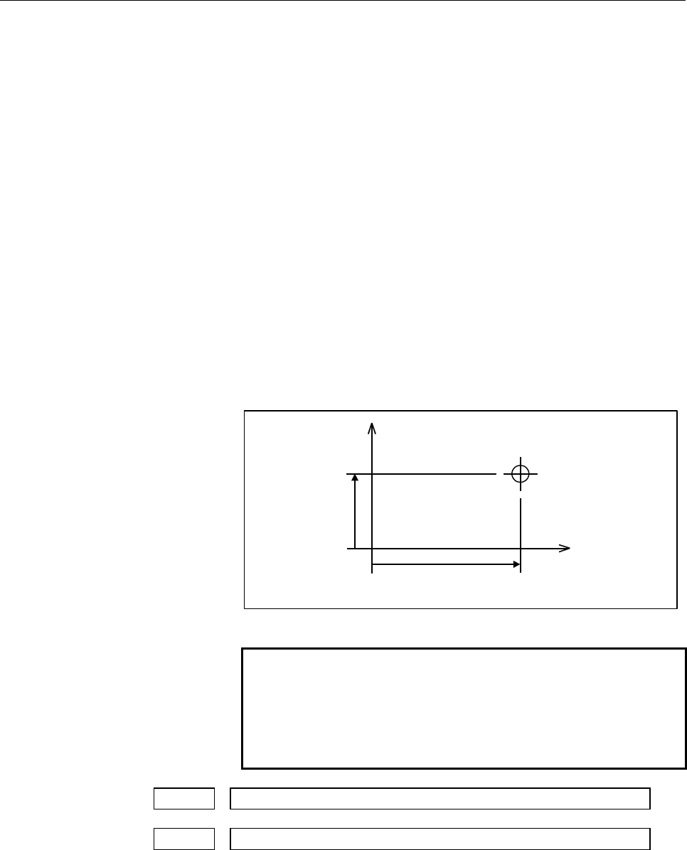
In polar coordinate interpolation mode, specify coordinates X-C (or
Y-A or Z-B) in the workpiece coordinate system with the origin set to
the center of rotary axis C (or A or B) set on each polar coordinate
interpolation plane in the following format:
G12.1 X_ C_ ;
(Polar coordinate interpolation with the X-axis and C-axis)
G12.1 Y_ A_ ;
(Polar coordinate interpolation with the Y-axis and A-axis)
G12.1 Z_ B_ ;
(Polar coordinate interpolation with the Z-axis and B-axis)
X
C
c
x
Center of the C-axis
Origin of the
workpiece
coordinate system
G12.1 Xx Cc ;
Example for polar coordinate interpolation with the X-axis and C-axis
NOTE
Carefully issue a command to shift the polar
coordinate interpolation coordinate system with this
parameter disabled because the command is
recognized as a move command and the machine
operates.
5460 Axis (linear axis) specification for polar coordinate interpolation
5461 Axis (rotary axis) specification for polar coordinate interpolation
[Data type] Byte
[Valid data range] 1, 2, 3, . . . Number of controlled axes
These parameters set controlled axis number of linear and rotary axes
to execute polar interpolation.
Contents Summary of Series 16i/160i/160is/18i/180i/180is - Model B Parameter manual
- Page 1FANUC Series 16*-MODEL B FANUC Series 18*-MODEL B FANUC Series 160*-MODEL B FANUC Series 180*-MODEL B FANUC Series 160*s-MODEL B FANUC Series 180*s-MODEL B PARAMETER MANUAL B-63530EN/03
- Page 2• No part of this manual may be reproduced in any form. • All specifications and designs are subject to change without notice. The export of this product is subject to the authorization of the government of the country from where the product is exported. In this manual we have tried as much as possi
- Page 3B-63530EN/03 DEFINITION OF WARNING, CAUTION, AND NOTE DEFINITION OF WARNING, CAUTION, AND NOTE This manual includes safety precautions for protecting the user and preventing damage to the machine. Precautions are classified into Warning and Caution according to their bearing on safety. Also, supplem
- Page 4
- Page 5B-63530EN/03 PREFACE PREFACE The models covered by this manual, and their abbreviations are : Model name Abbreviation FANUC Series 16i-TB 16i-TB Series 16i FANUC Series 16i-MB 16i-MB FANUC Series 160i-TB 160i-TB Series 160i FANUC Series 160i-MB 160i-MB FANUC Series 160is-TB 160is-TB Series 160is FAN
- Page 6PREFACE B-63530EN/03 Related manuals of Series 16i/18i/21i/160i/180i/210i/160is/180is/210is-MODEL B The following table lists the manuals related to Series 16i, Series 18i, Series 21i, Series 160i, Series 180i, Series 210i, Series 160is, Series 180is, Series 210is-MODEL B. This manual is indicated b
- Page 7B-63530EN/03 PREFACE Related manuals of SERVO MOTOR αi series The following table lists the manuals related to SERVO MOTOR αi series Manual name Specification number FANUC AC SERVO MOTOR αis series FANUC AC SERVO MOTOR αi series B-65262EN DESCRIPTIONS FANUC AC SPINDLE MOTOR αi series B-65272EN DESCR
- Page 8
- Page 9B-63530EN/03 TABLE OF CONTENTS TABLE OF CONTENTS DEFINITION OF WARNING, CAUTION, AND NOTE .................................s-1 PREFACE ....................................................................................................p-1 1 DISPLAYING PARAMETERS......................................
- Page 10TABLE OF CONTENTS B-63530EN/03 4.17 PARAMETERS OF ACCELERATION/DECELERATION CONTROL ........ 100 4.18 PARAMETERS OF SERVO (1 OF 2) ........................................................ 133 4.19 PARAMETERS OF DI/DO ......................................................................... 188 4.20
- Page 11B-63530EN/03 TABLE OF CONTENTS 4.47.1 Parameters of Graphic Display / Dynamic Graphic Display................................450 4.47.2 Parameters of Graphic Color ................................................................................455 4.48 PARAMETERS OF RUN HOUR AND PARTS COUNT DISPLAY.
- Page 12TABLE OF CONTENTS B-63530EN/03 4.73 OTHER PARAMETERS ............................................................................ 608 4.74 PARAMETERS OF TROUBLE DIAGNOSIS ............................................. 618 4.75 PARAMETERS OF MAINTENANCE ................................................
- Page 13B-63530EN/03 1.DISPLAYING PARAMETERS 1 DISPLAYING PARAMETERS Follow the procedure below to display parameters. (1) Press the SYSTEM function key on the MDI as many times as required, or alternatively, press the SYSTEM function key once, then the [PARAM] section display soft key. The parameter screen
- Page 142.SETTING PARAMETERS FROM MDI B-63530EN/03 2 SETTING PARAMETERS FROM MDI Follow the procedure below to set parameters. (1) Place the NC in the MDI mode or the emergency stop state. (2) Follow the substeps below to enable writing of parameters. 1. To display the setting screen, press the function key
- Page 15B-63530EN/03 2.SETTING PARAMETERS FROM MDI (5) Enter data, then press the [INPUT] soft key. The parameter indicated by the cursor is set to the entered data. [Example] 12000 [INPUT] Data can be entered continuously for parameters, starting at the selected parameter, by separating each data item with
- Page 163.INPUTTING AND OUTPUTTING PARAMETERS THROUGH THE READER/PUNCHER INTERFACE B-63530EN/03 3 INPUTTING AND OUTPUTTING PARAMETERS THROUGH THE READER/PUNCHER INTERFACE This section explains the parameter input/output procedures for input/output devices connected to the reader/puncher interface. The follo
- Page 17B-63530EN/03 3.INPUTTING AND OUTPUTTING PARAMETERS THROUGH THE READER/PUNCHER INTERFACE 3.1 OUTPUTTING PARAMETERS THROUGH THE READER/PUNCHER INTERFACE (1) Select the EDIT mode or set to Emergency stop. (2) To select the parameter screen, press the SYSTEM function key as many times as required, or al
- Page 183.INPUTTING AND OUTPUTTING PARAMETERS THROUGH THE READER/PUNCHER INTERFACE B-63530EN/03 3.2 INPUTTING PARAMETERS THROUGH THE READER/PUNCHER INTERFACE (1) Place the NC in the emergency stop state. (2) Enable parameter writing. 1. To display the setting screen, press the function key OFFSET SETTING as
- Page 19B-63530EN/03 4.DESCRIPTION OF PARAMETERS 4 DESCRIPTION OF PARAMETERS Parameters are classified by data type as follows: Table 4 Data Types and Valid Data Ranges of Parameters Data type Valid data range Remarks Bit 0 or 1 Bit axis Byte -128 to 127 In some parameters, signs are Byte axis 0 to 255 igno
- Page 204.DESCRIPTION OF PARAMETERS B-63530EN/03 NOTE 1 The bits left blank in Chapter 4 “DESCRIPTION OF PARAMETERS” and parameter numbers that appear on the display but are not found in the parameter list are reserved for future expansion. They must always be 0. 2 Parameters having different meanings betwe
- Page 21B-63530EN/03 4.DESCRIPTION OF PARAMETERS 4.1 PARAMETERS OF SETTING #7 #6 #5 #4 #3 #2 #1 #0 0000 SEQ INI ISO TVC At least one of these parameters can also be set on the “Setting screen”. [Data type] Bit TVC TV check 0 : Not performed 1 : Performed ISO Code used for data output 0 : EIA code 1 : ISO co
- Page 224.DESCRIPTION OF PARAMETERS B-63530EN/03 #7 #6 #5 #4 #3 #2 #1 #0 0002 SJZ RDG At least one of these parameters can also be set on the “Setting screen”. [Data type] Bit RDG Remote diagnosis is 0 : Not performed. 1 : Performed. To use an RS-232C serial port for performing remote diagnosis, connect and
- Page 23B-63530EN/03 4.DESCRIPTION OF PARAMETERS I/O CHANNEL: Selection of an input/output device or selection of input 0020 device in the foreground This parameter can also be set on the “Setting screen”. [Data type] Byte [Valid data range] 0 to 35 The CNC provides the following interfaces for data transfe
- Page 244.DESCRIPTION OF PARAMETERS B-63530EN/03 NOTE 1 An input/output device can also be selected using the setting screen. Usually, the setting screen is used. 2 The specifications (such as the baud rate and the number of stop bits) of the input/output devices to be connected must be set in the correspon
- Page 25B-63530EN/03 4.DESCRIPTION OF PARAMETERS 0021 Setting of the output device in the foreground 0022 Setting of the input device in the background 0023 Setting of the output device in the background These parameters can also be set on the “Setting screen”. [Data type] Byte [Valid data range] 0 to 3, 5,
- Page 264.DESCRIPTION OF PARAMETERS B-63530EN/03 4.2 PARAMETERS OF READER/PUNCHER INTERFACE OR REMOTE BUFFER To exchange data (such as programs and parameters) with an external input/output device by using the input/output device interface (RS-232C serial port) or remote buffer interface, the parameters des
- Page 27B-63530EN/03 4.DESCRIPTION OF PARAMETERS 4.2.1 Parameters Common to all Channels Port for communication with the PMC ladder development tool (FANUC 0024 LADDER-III) This parameter can also be set on the “Setting screen”. [Data type] Byte This parameter sets the port to be used for communication with
- Page 284.DESCRIPTION OF PARAMETERS B-63530EN/03 ND3 In DNC operation, a program is: 0 : Read block by block. (A DC3 code is output for each block.) 1 : Read continuously until the buffer becomes full. (A DC3 code is output when the buffer becomes full.) NOTE In general, reading is performed more efficientl
- Page 29B-63530EN/03 4.DESCRIPTION OF PARAMETERS HAD An alarm raised for the internal handy file is: 0 : Not displayed in detail on the NC screen. (PS alarm 86 is displayed.) 1 : Displayed in detail on the NC screen. ASI Code used at data input/output 0 : EIA or ISO code (Input: Automatic determination/Outp
- Page 304.DESCRIPTION OF PARAMETERS B-63530EN/03 0103 Baud rate (when the I/O CHANNEL is set to 0) [Data type] Byte Set baud rate of the input/output device used when the I/O CHANNEL is set to 0, with a set value in Table 4.2.2 (b). Table 4.2.2 (b) Set value Baud rate (bps) Set value Baud rate (bps) 1 50 9
- Page 31B-63530EN/03 4.DESCRIPTION OF PARAMETERS 0122 Number specified for the input/output device (when I/O CHANNEL is set to 2) [Data type] Byte Set the number specified for the input/output device used when I/O CHANNEL is set to 2, with a value in Table 4.2.2 (a). 0123 Baud rate (when the I/O CHANNEL is
- Page 324.DESCRIPTION OF PARAMETERS B-63530EN/03 0133 Baud rate (when the I/O CHANNEL is set to 3) NOTE When this parameter is set, the power must be turned off before operation is continued. [Data type] Byte Set the baud rate of the input/output device used when the I/O CHANNEL is set to 3 according to the
- Page 33B-63530EN/03 4.DESCRIPTION OF PARAMETERS #7 #6 #5 #4 #3 #2 #1 #0 0135 RMS R42 PRA ETX ASC NOTE When at least one of these parameters is set, the power must be turned off before operation is continued. [Data type] Bit ASC Communication code except NC data 0 : ISO code 1 : ASCII code ETX End code for
- Page 344.DESCRIPTION OF PARAMETERS B-63530EN/03 MDN The DNC operation function by a memory card is: 0 : Disabled. 1 : Enabled. (A PCMCIA card attachment is required.) NOTE Use a PCMCIA card attachment suited to the CNC to secure the memory card in the CNC. - 22 -
- Page 35B-63530EN/03 4.DESCRIPTION OF PARAMETERS 4.3 PARAMETERS OF DNC1/DNC2 INTERFACE #7 #6 #5 #4 #3 #2 #1 #0 0140 ECD NCE BCC NOTE When at least one of these parameters is set, the power must be turned off before operation is continued. [Data type] Bit BCC The BCC value (block check characters) is: 0 : Ch
- Page 364.DESCRIPTION OF PARAMETERS B-63530EN/03 0142 Station address of the CNC (DNC1 interface) NOTE When this parameter is set, the power must be turned off before operation is continued. [Data type] Byte [Valid data range] 2 to 52 This parameter specifies the station address of the CNC when the CNC is c
- Page 37B-63530EN/03 4.DESCRIPTION OF PARAMETERS 0146 Number of times the system retries holding communication (DNC2 interface) NOTE When this parameter is set, the power must be turned off before operation is continued. [Data type] Byte [Unit of data] Number of times [Valid data range] 1 to 10 (The standar
- Page 384.DESCRIPTION OF PARAMETERS B-63530EN/03 Number of characters in the data section of the communication packet 0149 (DNC2 interface) NOTE When this parameter is set, the power must be turned off before operation is continued. [Data type] Word [Valid range] 80 to 256 (The standard setting is 256.) If
- Page 39B-63530EN/03 4.DESCRIPTION OF PARAMETERS 4.4 PARAMETERS OF M-NET INTERFACE #7 #6 #5 #4 #3 #2 #1 #0 0161 SRS PEO SRP SRL NOTE When at least one of these parameters is set, the power must be turned off before operation is continued. [Data type] Bit SRL Number of characters used in the serial interface
- Page 404.DESCRIPTION OF PARAMETERS B-63530EN/03 0172 Length of DO data in bytes in M-NET NOTE When this parameter is set, the power must be turned off before operation is continued. [Data type] Byte [Valid range] 1 to 32 Specify the length of DO data in bytes (number of bytes of data actually transferred f
- Page 41B-63530EN/03 4.DESCRIPTION OF PARAMETERS 0175 Time required for connecting two stations in M-NET NOTE When this parameter is set, the power must be turned off before operation is continued. [Data type] Word [Unit of data] msec [Valid range] 1 to 32767 (The standard setting is 10000.) Specify a time
- Page 424.DESCRIPTION OF PARAMETERS B-63530EN/03 4.5 PARAMETERS OF REMOTE DIAGNOSIS #7 #6 #5 #4 #3 #2 #1 #0 0002 RDG [Data type] Bit RDG Remote diagnosis is: 0 : Not performed. 1 : Performed. If an RS-232C serial port is used to carry out remote diagnosis, connect and set up the modem, cable, and the like,
- Page 43B-63530EN/03 4.DESCRIPTION OF PARAMETERS 0203 Baud rate (for remote diagnosis) [Data type] Byte Set the baud rate of data input/output by remote diagnosis, with reference to the tables given below. When using an RS-232C serial port Set value Baud rate (bps) Set value Baud rate (bps) 1 50 7 600 2 100
- Page 444.DESCRIPTION OF PARAMETERS B-63530EN/03 0211 Password 1 for remote diagnosis 0212 Password 2 for remote diagnosis 0213 Password 3 for remote diagnosis [Data type] 2-word [Valid data range] 1 to 99999999 Specify a password for using the remote diagnosis function. The remote diagnosis function has th
- Page 45B-63530EN/03 4.DESCRIPTION OF PARAMETERS 0221 Keyword 1 for remote diagnosis 0222 Keyword 2 for remote diagnosis 0223 Keyword 3 for remote diagnosis [Data type] 2-word [Valid range] 1 to 99999999 Set a keyword corresponding to a password of the remote diagnosis function. Keyword 1: Keyword for passw
- Page 464.DESCRIPTION OF PARAMETERS B-63530EN/03 4.6 PARAMETERS OF DNC1 INTERFACE #2 #7 #6 #5 #4 #3 #2 #1 #0 0231 NFD ASI SB2 NOTE When at least one of these parameters is set, the power must be turned off before operation is continued. [Data type] Bit SB2 Number of stop bits 0 : 1 bit 1 : 2 bits ASI Data i
- Page 47B-63530EN/03 4.DESCRIPTION OF PARAMETERS 0241 Mode of connection between the host and CNC (DNC1 interface #2) NOTE When this parameter is set, the power must be turned off before operation is continued. [Data type] Byte [Valid data range] 1 or 2 This parameter sets the mode of connection between the
- Page 484.DESCRIPTION OF PARAMETERS B-63530EN/03 4.7 PARAMETERS OF MEMORY CARD INTERFACE #7 #6 #5 #4 #3 #2 #1 #0 0300 PCM [Data type] Bit PCM If the CNC screen display function is enabled, when a memory card interface is provided on the NC side, 0 : The memory card interface on the NC side is used. 1 : The
- Page 49B-63530EN/03 4.DESCRIPTION OF PARAMETERS 4.8 PARAMETERS OF FACTOLINK #7 #6 #5 #4 #3 #2 #1 #0 0801 SB2 [Data type] Bit SB2 The number of stop bits is: 0 : 1 bit. 1 : 2 bits. (Set the number of stop bits when an RS-232C port is specified as the FACTOLINK communication port.) 0802 Communication channel
- Page 504.DESCRIPTION OF PARAMETERS B-63530EN/03 FYR In the FACTOLINK clock display, years in the 99/01/23 00:00 format (bit 4 (FTM) of parameter No. 0810 set to 1) are represented: 0 : By a two-digit number. 1 : By a four-digit number. FTM The FACTOLINK clock is displayed in this format: 0 : Wed Nov 12 00:
- Page 51B-63530EN/03 4.DESCRIPTION OF PARAMETERS 4.9 PARAMETERS OF DATA SERVER #7 #6 #5 #4 #3 #2 #1 #0 0900 ONS DSV [Data type] Bit DSV The data server function is 0 : Enabled 1 : Disabled ONS When the O number of the data server file name and the O number in an NC program do not match: 0 : The O number of
- Page 524.DESCRIPTION OF PARAMETERS B-63530EN/03 4.10 PARAMETERS OF ETHERNET 0931 Special character code corresponding to soft key [CHAR-1] 0932 Special character code corresponding to soft key [CHAR-2] 0933 Special character code corresponding to soft key [CHAR-3] 0934 Special character code corresponding
- Page 53B-63530EN/03 4.DESCRIPTION OF PARAMETERS 4.11 PARAMETERS OF POWER MATE CNC MANAGER #7 #6 #5 #4 #3 #2 #1 #0 0960 2CH ASG SPW PMN MD2 MD1 SLV [Data type] Bit SLV When the power mate CNC manager is selected, the screen displays: 0 : One slave. 1 : Up to four slaves with the screen divided into four. MD
- Page 544.DESCRIPTION OF PARAMETERS B-63530EN/03 4.12 PARAMETERS OF AXIS CONTROL/INCREMENT SYSTEM #7 #6 #5 #4 #3 #2 #1 #0 1001 INM NOTE When at least one of these parameters is set, the power must be turned off before operation is continued. [Data type] Bit INM Least command increment on the linear axis 0 :
- Page 55B-63530EN/03 4.DESCRIPTION OF PARAMETERS AZR When no reference position is set, the G28 command causes: 0 : Reference position return using deceleration dogs (as during manual reference position return) to be executed. 1 : P/S alarm No.090 to be issued. NOTE When the function for setting the referen
- Page 564.DESCRIPTION OF PARAMETERS B-63530EN/03 IPI Bit 7 (IPR) of parameter No. 1004 is: 0 : Parameter that requires the power to be turned off before continuation of operation and is invalid in the case of inch input. 1 : Parameter that does not require the power to be turned off before continuation of o
- Page 57B-63530EN/03 4.DESCRIPTION OF PARAMETERS #7 #6 #5 #4 #3 #2 #1 #0 1005 RMBx MCCx EDMx EDPx HJZx DLZx ZRNx [Data type] Bit axis ZRNx When a command specifying the movement except for G28 is issued in automatic operation (memory, MDI, or DNC operation) and when a return to the reference position has no
- Page 584.DESCRIPTION OF PARAMETERS B-63530EN/03 HJZx When a reference position is already set: 0 : Manual reference position return is performed with deceleration dogs. 1 : Manual reference position return is performed using rapid traverse without deceleration dogs, or manual reference position return is p
- Page 59B-63530EN/03 4.DESCRIPTION OF PARAMETERS #7 #6 #5 #4 #3 #2 #1 #0 ZMIx DIAx ROSx ROTx 1006 ZMIx ROSx ROTx NOTE When at least one of these parameters is set, the power must be turned off before operation is continued. [Data type] Bit axis ROTx, ROSx Setting linear or rotary axis. ROSx ROTx Meaning Lin
- Page 604.DESCRIPTION OF PARAMETERS B-63530EN/03 ZMIx The direction of reference position return on each axis. 0 : Positive direction 1 : Negative direction NOTE The direction of the initial backlash, which occurs when power is switched on, is opposite to the direction of a reference position return. #7 #6
- Page 61B-63530EN/03 4.DESCRIPTION OF PARAMETERS OKIx Upon completion of reference position return in reference position setting with mechanical stopper: 0 : P/S alarm 000 is issued. (When reference position setting with mechanical stopper is used with this parameter setting, an absolute-position detector i
- Page 624.DESCRIPTION OF PARAMETERS B-63530EN/03 RABx In the absolute commands, the axis rotates in the direction 0 : In which the distance to the target is shorter. 1 : Specified by the sign of command value. NOTE RABx is valid only when ROAx is set to 1. RRLx Relative coordinates are 0 : Not rounded by th
- Page 63B-63530EN/03 4.DESCRIPTION OF PARAMETERS 1010 Number of CNC-controlled axes NOTE When this parameter is set, the power must be turned off before operation is continued. [Data type] Byte [Valid data range] 1, 2, 3, ..., the number of controlled axes Set the maximum number of axes that can be controll
- Page 644.DESCRIPTION OF PARAMETERS B-63530EN/03 #7 #6 #5 #4 #3 #2 #1 #0 1012 IDGx [Data type] Bit axis IDGx The function for setting the reference position again, without dogs, is: 0 : Not inhibited. 1 : Inhibited. NOTE 1 IDGx is enabled when bit 7 (IDG) of parameter No.1002 is set to 1. 2 When the functio
- Page 65B-63530EN/03 4.DESCRIPTION OF PARAMETERS ZRL For high-speed reference position return according to G28, second to fourth reference position return according to G30, and G53 command: 0 : Non-linear type positioning is performed. 1 : Linear type positioning is performed. This parameter is valid when b
- Page 664.DESCRIPTION OF PARAMETERS B-63530EN/03 1020 Program axis name for each axis [Data type] Byte axis Set the program axis name for each controlled axis, using one of the values listed in the following table: Axis Axis Axis Axis Setting Setting Setting Setting name name name name X 88 U 85 A 65 E 69 Y
- Page 67B-63530EN/03 4.DESCRIPTION OF PARAMETERS 1022 Setting of each axis in the basic coordinate system NOTE When this parameter is set, power must be turned off before operation is continued. [Data type] Byte axis To determine the following planes used for circular interpolation, cutter compensation C (f
- Page 684.DESCRIPTION OF PARAMETERS B-63530EN/03 1023 Number of the servo axis for each axis NOTE When this parameter is set, power must be turned off before operation is continued. [Data type] Byte axis [Valid data range] 1, 2, 3, ..., number of controlled axes /-1,-2,-3,-4 (-4 can be used in Series 16i/16
- Page 69B-63530EN/03 4.DESCRIPTION OF PARAMETERS 1031 Reference axis [Data type] Byte axis [Valid data range] 1, 2, 3, ..., number of controlled axes Some parameters for using high-precision/AI high-precision/AI nano high-precision contour control are common to all axes. The unit of some of those parameters
- Page 704.DESCRIPTION OF PARAMETERS B-63530EN/03 4.13 PARAMETERS OF COORDINATES #7 #6 #5 #4 #3 #2 #1 #0 WZR AWK FPC ZCL ZPI ZPR 1201 AWK FPC ZCL ZPI ZPR [Data type] Bit ZPR Automatic setting of a coordinate system when the manual reference position return is performed 0 : Not set automatically 1 : Set autom
- Page 71B-63530EN/03 4.DESCRIPTION OF PARAMETERS WZR Upon reset, the workpiece coordinate system is: 0 : Not returned to that specified with G54 1 : Returned to that specified with G54 NOTE If bit 2 (D3R) of parameter No. 5400 is set to 1, this parameter setting is ignored in the three-dimensional coordinat
- Page 724.DESCRIPTION OF PARAMETERS B-63530EN/03 G52 In local coordinate system setting (G52), a cutter compensation vector is: 0 : Not considered. 1 : Considered. NOTE Select a local coordinate system setting operation when cutter compensation is applied, and when two or more blocks specifying no movement
- Page 73B-63530EN/03 4.DESCRIPTION OF PARAMETERS WZP In the three-dimensional coordinate conversion mode, a modification to the workpiece coordinate system from the MDI is: 0 : Not prohibited. 1 : Prohibited. 3DW When any of the following: • Workpiece coordinate system selection (G54 to G59, G54.1P) • Coord
- Page 744.DESCRIPTION OF PARAMETERS B-63530EN/03 1220 External workpiece origin offset value [Data type] 2-word axis [Unit of data] Input increment IS-A IS-B IS-C Unit Linear axis (input in mm) 0.01 0.001 0.0001 mm Linear axis (input in inches) 0.001 0.0001 0.00001 inch Rotary axis 0.01 0.001 0.0001 deg [Va
- Page 75B-63530EN/03 4.DESCRIPTION OF PARAMETERS 1221 Workpiece origin offset value in workpiece coordinate system 1 (G54) 1222 Workpiece origin offset value in workpiece coordinate system 2 (G55) 1223 Workpiece origin offset value in workpiece coordinate system 3 (G56) 1224 Workpiece origin offset value in
- Page 764.DESCRIPTION OF PARAMETERS B-63530EN/03 Coordinate value of the first reference position on each axis in the machine 1240 coordinate system Coordinate value of the second reference position on each axis in the 1241 machine coordinate system Coordinate value of the third reference position on each a
- Page 77B-63530EN/03 4.DESCRIPTION OF PARAMETERS Address number of the internal relay (R signal) of the PMC for signal output of the first reference position 1245 Address number of the internal relay (R signal) of the PMC for signal output of the second reference position 1246 [Data type] Word [Unit of data
- Page 784.DESCRIPTION OF PARAMETERS B-63530EN/03 1260 Amount of a shift per one rotation of a rotary axis NOTE When this parameter is set, the power must be turned off before operation is continued. [Data type] 2-word axis [Unit of data] IS-A IS-B IS-C Unit of data 0.01 deg 0.001 deg 0.0001 deg Standard val
- Page 79B-63530EN/03 4.DESCRIPTION OF PARAMETERS 1290 Distance between two opposite tool posts in mirror image for double turret [Data type] 2-word [Unit of data] Input increment IS-A IS-B IS-C Unit Metric machine 0.01 0.001 0.0001 mm Inch machine 0.001 0.0001 0.00001 inch [Valid data range] 0 to 99999999 S
- Page 804.DESCRIPTION OF PARAMETERS B-63530EN/03 4.14 PARAMETERS OF STORED STROKE CHECK #7 #6 #5 #4 #3 #2 #1 #0 1300 BFA LZR RL3 LMS NAL OUT [Data type] Bit OUT The area inside or outside of the stored stroke check 2 is set as an inhibition area (setting by the parameters No.1322 and No.1323). 0 : Inside 1
- Page 81B-63530EN/03 4.DESCRIPTION OF PARAMETERS BFA When a command that exceeds a stored stroke check 1or 3 is issued 0 : An alarm is generated after the stroke check is exceeded. 1 : An alarm is generated before the stroke check is exceeded. NOTE The tool stops at a point up to F/7500 mm short of or ahead
- Page 824.DESCRIPTION OF PARAMETERS B-63530EN/03 OF1 If the tool is moved into the range allowed on the axis after an alarm is raised by stored stroke check 1, 0 : The alarm is not canceled before a reset is made. 1 : The OT alarm is immediately canceled. NOTE In the cases below, the automatic release funct
- Page 83B-63530EN/03 4.DESCRIPTION OF PARAMETERS Coordinate value of stored stroke check 1 in the positive direction on each 1320 axis Coordinate value of stored stroke check 1 in the negative direction on each 1321 axis [Data type] 2-word axis [Unit of data] Input increment IS-A IS-B IS-C Unit Metric machi
- Page 844.DESCRIPTION OF PARAMETERS B-63530EN/03 Coordinate value of stored stroke check 2 in the positive direction on each 1322 axis Coordinate value of stored stroke check 2 in the negative direction on each 1323 axis [Data type] 2-word axis [Unit of data] Input increment IS-A IS-B IS-C Unit Metric machi
- Page 85B-63530EN/03 4.DESCRIPTION OF PARAMETERS Coordinate value of stored stroke check 3 in the positive direction on each 1324 axis Coordinate value of stored stroke check 3 in the negative direction on each 1325 axis [Data type] 2-word axis [Unit of data] Input increment IS-A IS-B IS-C Unit Metric machi
- Page 864.DESCRIPTION OF PARAMETERS B-63530EN/03 4.15 PARAMETERS OF CHUCK AND TAILSTOCK BARRIER (T SERIES) 1330 Profile of a chuck [Data type] Byte [Valid data range] 0 or 1 0 : Chuck which holds a workpiece on the inner surface 1 : Chuck which holds a workpiece on the outer surface Dimensions of the claw o
- Page 87B-63530EN/03 4.DESCRIPTION OF PARAMETERS Chuck which holds a workpiece on the outer surface (TY= 1) Chuck which holds a workpiece on the inner surface (TY= 0) X X L A L A L1 W1 W W W1 CX L1 CX Z Z CZ CZ Zero point of the Zero point of the workpiece coordinate workpiece coordinate system system Symbo
- Page 884.DESCRIPTION OF PARAMETERS B-63530EN/03 L, L1, W and W1 Define the profile of a chuck. NOTE Always specify W and W1 with radiuses. Specify L and L1 with radiuses when the Z-axis conforms to radius programming. Length of a tailstock (L) 1341 Diameter of a tailstock (D) 1342 Length of a tailstock (L1
- Page 89B-63530EN/03 4.DESCRIPTION OF PARAMETERS X L L1 TZ L2 B Workpiece D3 D2 D1 D Z Zero point of the workpiece coordinate system Symbol Description TZ Z-axis coordinate of a tailstock L Length of a tailstock D Diameter of a tailstock (diameter input) L1 Length of a tailstock (1) D1 Diameter of a tailsto
- Page 904.DESCRIPTION OF PARAMETERS B-63530EN/03 4.16 PARAMETERS OF FEEDRATE #7 #6 #5 #4 #3 #2 #1 #0 RDR TDR RF0 JZR LRP RPD 1401 RDR TDR RF0 LRP RPD [Data type] Bit RPD Manual rapid traverse during the period from power-on time to the completion of the reference position return. 0 : Disabled (Jog feed is p
- Page 91B-63530EN/03 4.DESCRIPTION OF PARAMETERS #7 #6 #5 #4 #3 #2 #1 #0 JRV OV2 JOV NPC 1402 OV2 JOV NPC [Data type] Bit NPC The feed per rotation command is: 0 : Ineffective when a position coder is not provided. 1 : Effective even when a position coder is not provided (because the CNC converts it to the
- Page 924.DESCRIPTION OF PARAMETERS B-63530EN/03 #7 #6 #5 #4 #3 #2 #1 #0 RTV MIF 1403 NOTE When at least one of these parameters is set, the power must be turned off before operation is continued. [Data type] Bit MIF Cutting feedrates at feed per minute is specified by F commands 0 : In units of 1 mm/min fo
- Page 93B-63530EN/03 4.DESCRIPTION OF PARAMETERS
F8A Valid data range for an F command in feed-per-minute mode 0 : Range specified with bit 0 (MIF) of parameter No.1403 1: Input increment Units IS-A, IS-B IS-C Metric input mm/min 0.001 to 240000. 0.001 to 100000. Inch input inch/min 0.00001 t - Page 944.DESCRIPTION OF PARAMETERS B-63530EN/03 #7 #6 #5 #4 #3 #2 #1 #0 FCI EDR PCL 1405 FCI EDR FD3 F1U [Data type] Bit F1U Specifies the units of the data for the parameters that set the feedrates of the one-digit F code feed (parameter Nos. 1451 to 1459). Units of data Input increment When F1U is 0 When
- Page 95B-63530EN/03 4.DESCRIPTION OF PARAMETERS #7 #6 #5 #4 #3 #2 #1 #0 ED3 ED2 1406 [Data type] Bit ED2 External deceleration 2 is: 0 : Invalid. 1 : Valid. ED3 External deceleration 3 is: 0 : Invalid. 1 : Valid. #7 #6 #5 #4 #3 #2 #1 #0 RHT ACS 1407 ACF RHT ACS [Data type] Bit ACS If positioning of linear
- Page 964.DESCRIPTION OF PARAMETERS B-63530EN/03 #7 #6 #5 #4 #3 #2 #1 #0 1408 RFD [Data type] Bit axis RFD The feedrate about a rotary axis is controlled: 0 : In the usual method. 1 : By converting the rotation speed about the rotary axis into the travel speed on the circumference of a virtual circle. Set t
- Page 97B-63530EN/03 4.DESCRIPTION OF PARAMETERS 1414 Feedrate for retrace [Data type] 2-word This parameter sets the feedrate for retrace when the retrace function is used. (1) For rapid traverse [Unit of data, valid data range] Valid data range Input increment Unit of data IS-A, IS-B IS-C Metric machine 1
- Page 984.DESCRIPTION OF PARAMETERS B-63530EN/03 1421 F0 rate of rapid traverse override for each axis [Data type] Word axis [Unit of data, valid data range] Valid data range Input increment Unit of data IS-A, IS-B IS-C Metric machine 1 mm/min 30 to 15000 30 to 12000 Inch machine 0.1 inch/min 30 to 6000 30
- Page 99B-63530EN/03 4.DESCRIPTION OF PARAMETERS 1423 Feedrate in jog feed for each axis [Data type] Word axis (1) In M series, or in T series when bit 4 (JRV) of parameter No.1402, is set to 0 (feed per minute), specify a jog feedrate at feed per minute with a manual feedrate override of 100%. [Unit of dat
- Page 1004.DESCRIPTION OF PARAMETERS B-63530EN/03 1425 FL rate of the reference position return for each axis [Data type] Word axis [Unit of data, valid data range] Valid data range Input increment Unit of data IS-A, IS-B IS-C Metric machine 1 mm/min 6 to 15000 6 to 12000 Inch machine 0.1 inch/min 6 to 6000
- Page 101B-63530EN/03 4.DESCRIPTION OF PARAMETERS 1428 Reference position return feedrate for each axis [Data type] 2-word axis [Unit of data, valid data range] Valid data range Input increment Unit of data IS-A, IS-B IS-C Metric machine 1 mm/min 30 to 240000 6 to 100000 Inch machine 0.1 inch/min 30 to 96000
- Page 1024.DESCRIPTION OF PARAMETERS B-63530EN/03 1430 Maximum cutting feedrate for each axis [Data type] 2-word axis [Unit of data, valid data range] Valid data range Input increment Unit of data IS-A, IS-B IS-C Metric machine 1 mm/min 6 to 240000 6 to 100000 Inch machine 0.1 inch/min 6 to 96000 6 to 48000
- Page 103B-63530EN/03 4.DESCRIPTION OF PARAMETERS 1431 Maximum cutting feedrate for all axes in the advanced preview control mode [Data type] 2-word [Unit of data, valid data range] Valid data range Input increment Unit of data IS-A, IS-B IS-C Metric machine 1 mm/min 0 to 240000 0 to 100000 Inch machine 0.1
- Page 1044.DESCRIPTION OF PARAMETERS B-63530EN/03 Maximum cutting feedrate for each axis in the AI contour control mode or 1432 advanced preview control mode [Data type] 2-word axis [Unit of data, valid data range] Valid data range Input increment Unit of data IS-A, IS-B IS-C Metric machine 1 mm/min 0 to 240
- Page 105B-63530EN/03 4.DESCRIPTION OF PARAMETERS Maximum allowable feedrate for the feedrate check function for each axis 1436 [Data type] 2-word axis [Unit of data, valid data range] Valid data range Input increment Unit of data IS-A, IS-B IS-C Metric machine 1 mm/min 0, 30 to 240000 0, 6 to 100000 Inch ma
- Page 1064.DESCRIPTION OF PARAMETERS B-63530EN/03 1442 Maximum allowable manual handle feedrate 2 for each axis [Data type] Word axis [Unit of data, valid data range] Valid data range Input increment Unit of data IS-A, IS-B IS-C Metric machine 1 mm/min 6 to 15000 6 to 12000 Inch machine 0.1 inch/min 6 to 600
- Page 107B-63530EN/03 4.DESCRIPTION OF PARAMETERS Change of feedrate for one graduation on the manual pulse generator during 1450 one-digit F feed code [Data type] Byte [Valid data range] 1 to 127 Set the constant that determines the change in feedrate as the manual pulse generator is rotated one graduation
- Page 1084.DESCRIPTION OF PARAMETERS B-63530EN/03 1451 Feedrate for one-digit F code feed command F1 1452 Feedrate for one-digit F code feed command F2 1453 Feedrate for one-digit F code feed command F3 1454 Feedrate for one-digit F code feed command F4 1455 Feedrate for one-digit F code feed command F5 1456
- Page 109B-63530EN/03 4.DESCRIPTION OF PARAMETERS 1460 Upper limit of feedrate for the one-digit F code feed command (F1 to F4) 1461 Upper limit of feedrate for the one-digit F code feed command (F5 to F9) [Data type] 2-word [Unit of data, valid data range] Valid data range Input increment Unit of data IS-A,
- Page 1104.DESCRIPTION OF PARAMETERS B-63530EN/03 1465 Virtual radius for feedrate control about rotary axis [Data type] 2-word axis [Unit of data] Input increment IS-A IS-B IS-C Unit Metric input mm 0.01 0.001 0.0001 Inch input inch [Valid data range] 0 to 99999999 Set the radius of a virtual circle when us
- Page 111B-63530EN/03 4.DESCRIPTION OF PARAMETERS Feedrate for retraction in a threading cycle 1466 [Data type] 2-word [Unit of data, valid data range] Valid data range Input increment Unit of data IS-A, IS-B IS-C Metric machine 1 mm/min 30 to 240000 6 to 100000 Inch machine 0.1 inch/min 30 to 96000 6 to 480
- Page 1124.DESCRIPTION OF PARAMETERS B-63530EN/03 4.17 PARAMETERS OF ACCELERATION/DECELERATION CONTROL #7 #6 #5 #4 #3 #2 #1 #0 NCI RTO 1601 ACD NCI RTO OVB [Data type] Bit OVB Block overlap in cutting feed 0 : Blocks are not overlapped in cutting feed. 1 : Blocks are overlapped in cutting feed. Block overlap
- Page 113B-63530EN/03 4.DESCRIPTION OF PARAMETERS ACD Automatic corner deceleration function is: 0 : Not used. 1 : Used. #7 #6 #5 #4 #3 #2 #1 #0 LS2 G8S BS2 COV FWB 1602 LS2 G8S CSD BS2 COV FWB [Data type] Bit FWB Cutting feed acceleration/deceleration before interpolation 0 : Type A of acceleration/decelera
- Page 1144.DESCRIPTION OF PARAMETERS B-63530EN/03 BS2 The type of acceleration/deceleration after interpolation for cutting feed in the advanced preview control mode/high-precision contour control mode or in the AI high-precision/AI nano high-precision contour control mode is: 0 : Specified by bit 6 (LS2) of
- Page 115B-63530EN/03 4.DESCRIPTION OF PARAMETERS LS2 The type of acceleration/deceleration when bit 3 (BS2) of parameter No. 1602 is set to 0 is: 0 : Exponential acceleration/deceleration, or no acceleration/ deceleration is applied. 1 : Linear acceleration/deceleration. (The function for linear acceleratio
- Page 1164.DESCRIPTION OF PARAMETERS B-63530EN/03 PRT The acceleration/deceleration of interpolation-type rapid traverse is performed: 0 : With a constant inclination. 1 : With a constant time. NOTE 1 An acceleration/deceleration time constant and override for rapid traverse are used. 2 Rapid traverse block
- Page 117B-63530EN/03 4.DESCRIPTION OF PARAMETERS #7 #6 #5 #4 #3 #2 #1 #0 1610 JGLx CTBx CTLx [Data type] Bit axis CTLx Acceleration/deceleration in cutting feed including feed in dry run 0 : Exponential acceleration/deceleration is applied. 1 : Linear acceleration/deceleration after interpolation is applied
- Page 1184.DESCRIPTION OF PARAMETERS B-63530EN/03 Time constant T or T1 used for linear acceleration/deceleration or 1620 bell-shaped acceleration/deceleration in rapid traverse for each axis [Data type] Word axis [Unit of data] msec [Valid data range] 0 to 4000 Specify a time constant used for acceleration/
- Page 119B-63530EN/03 4.DESCRIPTION OF PARAMETERS
Speed Rapid traverse rate Time T2/ T1 T2/2 T2 T1: Set a time constant used for linear acceleration/deceleration. T2: Set a time for rounding. Total time=T1 + T2 Time for linear=T1 - T2 Time for rounding p - Page 1204.DESCRIPTION OF PARAMETERS B-63530EN/03 Time constant of exponential acceleration/deceleration in cutting feed for 1622 each axis [Data type] Word axis [Unit of data] msec [Valid data range] 0 to 4000 (exponential acceleration/deceleration in cutting feed) 0 to 512 (linear or bell-shaped accelerati
- Page 121B-63530EN/03 4.DESCRIPTION OF PARAMETERS 1623 FL rate of exponential acceleration/deceleration in cutting feed for each axis [Data type] Word axis [Unit of data, valid data range] Valid data range Input increment Unit of data IS-A, IS-B IS-C Metric machine 1 mm/min 0, 6 to 15000 0, 6 to 12000 Inch m
- Page 1224.DESCRIPTION OF PARAMETERS B-63530EN/03 Time constant of exponential acceleration/deceleration in the threading cycle for each axis 1626 [Data type] Word axis [Unit of data] msec [Valid data range] 0 to 4000 Set the time constant used for exponential acceleration/deceleration in the threading cycle
- Page 123B-63530EN/03 4.DESCRIPTION OF PARAMETERS Parameter 1 for setting an acceleration for linear acceleration/deceleration 1630 before interpolation (maximum machining feedrate during linear acceleration/deceleration before interpolation) [Data type] 2-word [Unit of data, valid data range] Valid data ran
- Page 1244.DESCRIPTION OF PARAMETERS B-63530EN/03 Parameter 2 for setting an acceleration for linear acceleration/deceleration 1631 before interpolation (time used to reach the maximum machining speed during linear acceleration/deceleration before interpolation.) [Data type] Word [Unit of data] 1 msec [Valid
- Page 125B-63530EN/03 4.DESCRIPTION OF PARAMETERS Minimum deceleration ratio (MDR) of the inner circular cutting rate in 1710 automatic corner override [Data type] Byte [Unit of data] % [Valid data range] 1 to 100 This parameter sets the minimum deceleration ratio (MDR) when the inner circular cutting speed
- Page 1264.DESCRIPTION OF PARAMETERS B-63530EN/03 1713 Distance Le from the starting point in inner corner override [Data type] 2-word [Unit of data] Input increment IS-A IS-B IS-C Unit Metric input 1 0.1 0.01 mm Inch input 0.1 0.01 0.001 inch [Valid data range] 0 to 3999 This parameter sets the distance Le
- Page 127B-63530EN/03 4.DESCRIPTION OF PARAMETERS 1722 Rapid traverse feedrate reduction ratio for overlapping rapid traverse blocks [Data type] Byte axis [Unit of data] % [Valid data range] 1 to 100 This parameter is used when rapid traverse blocks are arranged successively, or when a rapid traverse block i
- Page 1284.DESCRIPTION OF PARAMETERS B-63530EN/03 1731 Arc radius value corresponding to a maximum feedrate [Data type] 2-word [Unit of data] Input increment IS-A IS-B IS-C Unit Linear axis (millimeter machine) 0.01 0.001 0.0001 mm Linear axis (inch machine) 0.001 0.0001 0.00001 inch [Valid data range] 1000
- Page 129B-63530EN/03 4.DESCRIPTION OF PARAMETERS 1741 Feedrate for assuming the termination of automatic corner deceleration (for acceleration/deceleration after interpolation) [Data type] Word axis [Unit of data, valid data range] Valid data range Input increment Unit of data IS-A, IS-B IS-C Metric machine
- Page 1304.DESCRIPTION OF PARAMETERS B-63530EN/03 Time constant for linear acceleration/deceleration or bell-shaped acceleration/deceleration during cutting feed in advanced preview control mode, AI contour control mode, or AI nano contour control mode 1768 or Time constant for acceleration/deceleration afte
- Page 131B-63530EN/03 4.DESCRIPTION OF PARAMETERS Time constant for linear acceleration/deceleration or bell-shaped acceleration/deceleration during cutting feed in advanced preview control 1769 mode, AI contour control mode, AI nano contour control mode, high-precision contour control mode, AI high-precisio
- Page 1324.DESCRIPTION OF PARAMETERS B-63530EN/03 Parameter 1 for setting an acceleration for linear acceleration/deceleration 1770 before interpolation (maximum machining speed during linear acceleration/deceleration before interpolation) [Data type] 2-word [Unit of data, valid data range] Valid data range
- Page 133B-63530EN/03 4.DESCRIPTION OF PARAMETERS Parameter 2 for setting an acceleration for linear acceleration/deceleration 1771 before interpolation (time used to reach the maximum machining speed during linear acceleration/deceleration before interpolation) [Data type] Word [Unit of data] msec [Valid ra
- Page 1344.DESCRIPTION OF PARAMETERS B-63530EN/03 Time constant for bell-shaped acceleration/deceleration of acceleration time 1772 fixed type before look-ahead interpolation [Data type] Byte [Unit of data] msec [Valid data range] 0 to 255 This parameter is used to set a time constant when bit 7 (BEL) of par
- Page 135B-63530EN/03 4.DESCRIPTION OF PARAMETERS Time constant T1 used for bell-shaped acceleration/deceleration in rapid traverse for each axis, or time constant T used for linear 1773 acceleration/deceleration in rapid traverse for each axis applicable to the optimum torque acceleration/deceleration funct
- Page 1364.DESCRIPTION OF PARAMETERS B-63530EN/03 NOTE 1 Parameter No. 1773 cannot be used in the ordinary operation mode, advanced preview control mode, and AI advanced preview control mode. Use parameter No. 1620. 2 If the parameter or parameters indicated below are used, acceleration/deceleration before i
- Page 137B-63530EN/03 4.DESCRIPTION OF PARAMETERS Time constant t T2 for each axis used for bell-shaped 1774 acceleration/deceleration in rapid traverse of optimum torque acceleration/deceleration [Data type] Word axis [Unit of data] msec [Valid data range] Function name Valid data range Ordinary operation 0
- Page 1384.DESCRIPTION OF PARAMETERS B-63530EN/03 Tangent speed Automatically calculate the maximum acceleration that does not exceed the maximum allowable acceleration of each axis. (A) (B) (C) (B) (A) (B) (C) (B) (A) Set the time in parameter No. 1774. NOTE 1 Parameter No. 1774 cannot be used in the ordina
- Page 139B-63530EN/03 4.DESCRIPTION OF PARAMETERS 1777 Minimum speed for the automatic corner deceleration function (for advanced preview control) [Data type] Word [Unit of data, valid data range] Valid data range Input increment Unit of data IS-A, IS-B IS-C Metric machine 1 mm/min 6 to 15000 6 to 12000 Inch
- Page 1404.DESCRIPTION OF PARAMETERS B-63530EN/03 1779 Critical angle subtended by two blocks for automatic corner deceleration (for advanced preview control) [Data type] 2-word [Unit of data] 0.001 deg [Valid data range] 0 to 180000 Set a critical angle to be subtended by two blocks for corner deceleration
- Page 141B-63530EN/03 4.DESCRIPTION OF PARAMETERS Allowable speed difference for the speed difference based corner 1783 deceleration function (for linear acceleration/deceleration before interpolation) [Data type] Word axis [Unit of data, valid data range] Valid data range Input increment Unit of data IS-A,
- Page 1424.DESCRIPTION OF PARAMETERS B-63530EN/03 Parameter for determining an allowable acceleration when the feedrate is set 1785 by acceleration [Data type] Word axis [Unit of data] msec [Valid data range] 0 to 32767 This parameter sets the time required to attain the maximum cutting feedrate to determine
- Page 143B-63530EN/03 4.DESCRIPTION OF PARAMETERS 1787 Time constant for bell-shaped acceleration/deceleration of acceleration time fixed type before look-ahead interpolation in the AI contour control mode or AI nano contour control mode (for a rotary axis) [Data type] Byte [Unit of data] msec [Valid data ra
- Page 1444.DESCRIPTION OF PARAMETERS B-63530EN/03 Allowable amount of acceleration change for each axis in speed control based on acceleration change under jerk control when linear interpolation 1789 operations are performed successively (for AI contour control (M series)/AI nano contour control (M/T series)
- Page 145B-63530EN/03 4.DESCRIPTION OF PARAMETERS 4.18 PARAMETERS OF SERVO (1 OF 2) #7 #6 #5 #4 #3 #2 #1 #0 1800 TRC RBK FFR OZR CVR [Data type] Bit CVR When velocity control ready signal VRDY is set ON before position control ready signal PRDY comes ON 0 : A servo alarm is generated. 1 : A servo alarm is no
- Page 1464.DESCRIPTION OF PARAMETERS B-63530EN/03 CIN When bit 4 (CCI) of parameter No.1801 = 1, the in-position area for cutting feed is: 0 : Use value in parameter No.1827 if the next block is also for cutting feed, or use value in parameter No.1826 if the next block is not for cutting feed. 1 : Use value
- Page 147B-63530EN/03 4.DESCRIPTION OF PARAMETERS DC2 The reference position on the linear scale with absolute address reference marks is established: 0 : As determined by bit 1 (DC4) of parameter No. 1802. 1 : By establishing the absolute position through detection of two reference marks. NOTE 1 When using
- Page 1484.DESCRIPTION OF PARAMETERS B-63530EN/03 #7 #6 #5 #4 #3 #2 #1 #0 1804 SAK ANA IVO BLC [Data type] Bit axis BLC During circular interpolation by jog feed (manual circular interpolation function), the backlash acceleration function is: 0 : Disabled. 1 : Enabled. IVO When an attempt is made to release
- Page 149B-63530EN/03 4.DESCRIPTION OF PARAMETERS #7 #6 #5 #4 #3 #2 #1 #0 1807 SWP [Data type] Bit SWP This parameter specifies an operation to be performed in a warning state (such as the stop of a fan) of the αi servo amplifier. 0 : An alarm is issued when the amplifier is in a warning state. Automatic ope
- Page 1504.DESCRIPTION OF PARAMETERS B-63530EN/03 DCLx As a separate position detector: 0 : An encoder with absolute address reference marks (linear scale/rotary encoder)/encoder with distance-coded reference marks (linear scale/rotary encoder) (detection circuit C) is not used. 1 : An encoder with absolute
- Page 151B-63530EN/03 4.DESCRIPTION OF PARAMETERS APCx Position detector 0 : Other than absolute position detector 1 : Absolute position detector (absolute Pulsecoder) For an absolute-position system using Inductosyn, set this parameter to 1. NRTx When the machine coordinate on a rotary axis passes 0 deg or
- Page 1524.DESCRIPTION OF PARAMETERS B-63530EN/03 SCRx To set rotary axis B type for a rotary axis that uses a scale with no speed data, speed data conversion is: 0 : Not performed. 1 : Performed. NOTE 1 This parameter is valid only for an axis of rotary axis B type. 2 Do not set this parameter even for an a
- Page 153B-63530EN/03 4.DESCRIPTION OF PARAMETERS #7 #6 #5 #4 #3 #2 #1 #0 1818 SDCx DG0x RF2x RFSx [Data type] Bit axis RFSx If automatic reference position return (G28) is specified when no reference position is established on an axis for which an encoder with absolute address reference marks (linear scale/
- Page 1544.DESCRIPTION OF PARAMETERS B-63530EN/03 #7 #6 #5 #4 #3 #2 #1 #0 DATx CRFx FUPx 1819 NAHx DATx CRFx FUPx [Data type] Bit axis FUPx To perform follow-up when the servo is off is set for each axis. 0 : The follow-up signal, *FLWU, determines whether follow-up is performed or not. When *FLWU is 0, foll
- Page 155B-63530EN/03 4.DESCRIPTION OF PARAMETERS 1820 Command multiplier for each axis (CMR) NOTE When this parameter is set, the power must be turned off before operation is continued. [Data type] Byte axis Set a command multiplier indicating the ratio of the least command increment to the detection unit f
- Page 1564.DESCRIPTION OF PARAMETERS B-63530EN/03 Setting command multiply (CMR), detection multiply (DMR), and the capacity of the reference counter + DA × CMR Error counter Converter To velocity Least command - control increment Feedback pulse Reference counter × DMR Position detector Detection unit Set th
- Page 157B-63530EN/03 4.DESCRIPTION OF PARAMETERS 1821 Reference counter size for each axis NOTE When this parameter is set, the power must be turned off before operation is continued. [Data type] 2-word axis [Unit of data] Detection unit [Valid data range] 0 to 99999999 Set the size of the reference counter
- Page 1584.DESCRIPTION OF PARAMETERS B-63530EN/03 1826 In-position width for each axis [Data type] Word axis [Unit of data] Detection unit [Valid data range] 0 to 32767 The in-position width is set for each axis. When the deviation of the machine position from the specified position (the absolute value of th
- Page 159B-63530EN/03 4.DESCRIPTION OF PARAMETERS 1830 Axis-by-axis positional deviation limit at servo-off time [Data type] 2-word axis [Unit of data] Detection unit [Valid data range] 0 to 99999999 This parameter is used to set a positional deviation limit at servo-off time, on an axis-by-axis basis. If th
- Page 1604.DESCRIPTION OF PARAMETERS B-63530EN/03 1836 Servo error amount where reference position return is possible [Data type] Byte axis [Unit of data] Detection unit [Valid data range] 0 to 127 This parameter sets a servo error used to enable reference position return in manual reference position return.
- Page 161B-63530EN/03 4.DESCRIPTION OF PARAMETERS 1846 Distance for starting the second smooth backlash compensation NOTE When this parameter is set, the power must be turned off before operation is continued. [Data type] 2-word axis [Unit of data] Detection unit [Valid data range] 0 to 99999999 For each axi
- Page 1624.DESCRIPTION OF PARAMETERS B-63530EN/03 1848 Compensation value of the first smooth backlash compensation NOTE When this parameter is set, the power must be turned off before operation is continued. [Data type] Word axis [Unit of data] Detection unit [Valid data range] -9999 to 9999 For each axis,
- Page 163B-63530EN/03 4.DESCRIPTION OF PARAMETERS 1852 Backlash compensation value used for rapid traverse for each axis [Data type] Word axis [Unit of data] Detection unit [Valid data range] -9999 to +9999 Set the backlash compensation value used in rapid traverse for each axis. (This parameter is valid whe
- Page 1644.DESCRIPTION OF PARAMETERS B-63530EN/03 1867 Threshold value for scale data conversion (common to all axes) [Data type] 2-word [Unit of data] Input increment IS-A IS-B IS-C Unit Rotary axis 0.01 0.001 0.0001 deg [Valid data range] 0 to 99999999 If scale data is greater than the setting of this para
- Page 165B-63530EN/03 4.DESCRIPTION OF PARAMETERS 1868 Threshold value for scale data conversion (for each axis) [Data type] 2-word axis [Unit of data] Input increment IS-A IS-B IS-C Unit Rotary axis 0.01 0.001 0.0001 deg [Valid data range] 0 to 99999999 If scale data is greater than the setting of this para
- Page 1664.DESCRIPTION OF PARAMETERS B-63530EN/03 1874 Numerator of the conversion coefficient for inductosyn position detection 1875 Denominator of the conversion coefficient for inductosyn position detection NOTE When this parameter is set, the power must be turned off before operation is continued. [Data
- Page 167B-63530EN/03 4.DESCRIPTION OF PARAMETERS 1881 Group number when an unexpected disturbance torque is detected [Data type] Byte axis [Valid data range] 0 to 8 This parameter sets the group number of each axis, used when an unexpected disturbance torque is detected. If an unexpected disturbance torque
- Page 1684.DESCRIPTION OF PARAMETERS B-63530EN/03 Distance 1 from the mark origin of an encoder with absolute addressing 1883 reference marks/encoder with distance-coded reference marks (detection circuit C) to the reference position NOTE When this parameter is set, the power must be turned off before operat
- Page 169B-63530EN/03 4.DESCRIPTION OF PARAMETERS Reference position Encoder origin Encoder end Mark 1 Mark 2 Mark 1 マ Mark 2 Mark 1 = Mark 2 ..... 8.0 42.0 8.2 41.8 Parameter No. 1821 Parameter No. 1882 (Parameter No. 1884) × 100,000,000 + (Parameter No. 1883) [Example of parameter setting] When an encoder
- Page 1704.DESCRIPTION OF PARAMETERS B-63530EN/03 1 Set bit 1 (OPTx) of parameter No. 1815 to 1, bit 2 (DCLx) of parameter No. 1815 to 1, and bit 3 (DCRx) of parameter No. 1815 to 0/1 to enable an encoder with absolute addressing reference marks (linear scale/rotary encoder). Set a proper value in parameter
- Page 171B-63530EN/03 4.DESCRIPTION OF PARAMETERS 1885 Maximum allowable value for total travel during torque control [Data type] Word axis [Unit of data] Detection unit [Valid data range] 0 to 32767 This parameter sets the maximum allowable value for the total travel (error counter value) for an axis placed
- Page 1724.DESCRIPTION OF PARAMETERS B-63530EN/03 1891 Initial value of the Y address where motor speed detection signals are output NOTE When this parameter is set, the power must be turned off before operation is continued. [Data type] Word [Valid data range] 0 to 126, 1000 to 1013, 1020 to 1033 This param
- Page 173B-63530EN/03 4.DESCRIPTION OF PARAMETERS 1895 Servo motor axis number used for a milling tool [Data type] Byte [Valid data range] 1, 2, 3, ..., number of controlled axes This parameter sets the servo motor axis number used for displaying the speed of a milling tool that incorporates a servo motor. 1
- Page 1744.DESCRIPTION OF PARAMETERS B-63530EN/03 #7 #6 #5 #4 #3 #2 #1 #0 1902 DCE STP ASE FMD NOTE When at least one of these parameters is set, the power must be turned off before operation is continued. WARNING Be sure to set bits 5 and 7 of parameter No. 1902 to 0. If any of these bits is set to 1, the s
- Page 175B-63530EN/03 4.DESCRIPTION OF PARAMETERS STP When the dual check safety function is used, an MCC off Test at power-off time is: 0 : Conducted. (When the power is turned on, the warning "Conduct Safety Test." is indicated, and the MCC off Test execution request signal RQT is output.) 1 : Not conducte
- Page 1764.DESCRIPTION OF PARAMETERS B-63530EN/03 FO2 The second FSSB I/O unit is: 0 : Not used. 1 : Used. NOTE 1 On the FSSB, an FSSB I/O module and separate detector interface unit (pulse module) are handled as units of the same type. The term "first unit" or "second unit" used in the descriptions here rep
- Page 177B-63530EN/03 4.DESCRIPTION OF PARAMETERS DCNx The checks of the target axis by the dual check safety function are: 0 : Made. 1 : Not made. CAUTION 1 The DCN bit cannot disable the checks by the dual check safety function for all the controlled axes. 2 Set the DCN bit to 1 for the slave axis under ta
- Page 1784.DESCRIPTION OF PARAMETERS B-63530EN/03 #7 #6 #5 #4 #3 #2 #1 #0 1905 PM2x PM1x IO2x IO1x FSLx NOTE When at least one of these parameters is set, the power must be turned off before operation is continued. [Data type] Bit axis FSLx The type of interface used between the servo amplifier and servo sof
- Page 179B-63530EN/03 4.DESCRIPTION OF PARAMETERS IO2x A second I/O module supporting FSSB is: 0 : Not used. 1 : Used. NOTE 1 On the FSSB, an FSSB I/O unit and separate detector interface unit (pulse module) are handled as units of the same type. The term "first unit" or "second unit" used in the description
- Page 1804.DESCRIPTION OF PARAMETERS B-63530EN/03 1910 Address conversion table value for slave 1 (ATR) 1911 Address conversion table value for slave 2 (ATR) 1912 Address conversion table value for slave 3 (ATR) 1913 Address conversion table value for slave 4 (ATR) 1914 Address conversion table value for sla
- Page 181B-63530EN/03 4.DESCRIPTION OF PARAMETERS NOTE 1 When using the simple electric gear box (EGB) function The EGB axis (axis set with parameter No.7771) does not actually require an amplifier. So, assume that the EGB axis is connected to a dummy amplifier. Accordingly, as the address conversion table v
- Page 1824.DESCRIPTION OF PARAMETERS B-63530EN/03 • Examples of axis configurations and parameter settings CNC Controlled Program Servo axis Slave ATR axis axis name number number No.1910 Axis number No.1020 No.1023 to 1919 1 X 1 1-axis 2 Y 3 1 0 X amplifier 3 Z 4 4 A 2 2-axis 2 1 A amplifier 3 2 Y 5 B 5 6 C
- Page 183B-63530EN/03 4.DESCRIPTION OF PARAMETERS • Example of axis configuration and parameter settings when the simple electric gear box (EGB) function is used (EGB workpiece axes: A axis, EGB axis, B axis (Parameter No.7771=5)) CNC Controlled Program Servo axis Slave ATR axis axis name number number No.19
- Page 1844.DESCRIPTION OF PARAMETERS B-63530EN/03 1920 Controlled axis number for slave 1 (dedicated to the FSSB setting screen) 1921 Controlled axis number for slave 2 (dedicated to the FSSB setting screen) 1922 Controlled axis number for slave 3 (dedicated to the FSSB setting screen) 1923 Controlled axis n
- Page 185B-63530EN/03 4.DESCRIPTION OF PARAMETERS Connector number for the first separate detector interface unit (dedicated to 1931 the FSSB setting screen) Connector number for the second separate detector interface unit (dedicated 1932 to the FSSB setting screen) NOTE When these parameters are set, the po
- Page 1864.DESCRIPTION OF PARAMETERS B-63530EN/03 Master and slave axis numbers subject to tandem control (dedicated to the 1934 FSSB setting screen) NOTE When this parameter is set, the power must be turned off before operation is continued. [Data type] Byte axis [Valid data range] 0 to 8 This parameter is
- Page 187B-63530EN/03 4.DESCRIPTION OF PARAMETERS 1936 Connector number of the first separate detector interface unit 1937 Connector number of the second separate detector interface unit NOTE When these parameters are set, the power must be turned off before operation is continued. [Data type] Byte axis [Val
- Page 1884.DESCRIPTION OF PARAMETERS B-63530EN/03 1942 Safety speed for each axis 13821 Safety speed 1 for each axis 13822 Safety speed 2 for each axis 13823 Safety speed 3 for each axis 13824 Safety speed 4 for each axis [Data type] 2-word axis [Unit of data, valid data range] Valid data range Input increme
- Page 189B-63530EN/03 4.DESCRIPTION OF PARAMETERS 1943 Safe machine position of each axis (+ direction) 1944 Safe machine position of each axis (- direction) 13831 Safe machine position 1 of each axis (+ direction) 13832 Safe machine position 1 of each axis (- direction) 13833 Safe machine position 2 of each
- Page 1904.DESCRIPTION OF PARAMETERS B-63530EN/03 NOTE 1 Safe machine position monitoring is performed only for a linear axis. Safe machine position monitoring is not performed for a rotary axis. 2 Safe machine position monitoring is performed only for an axis that has a reference position already establishe
- Page 191B-63530EN/03 4.DESCRIPTION OF PARAMETERS 1946 MCC off Test timer [Data type] Word [Unit of data] msec [Valid data range] 0 to 32767 When MCC off Test mode is set with the dual check safety function, the CNC conducts a safety output signal MCC off Test. If a MCC off Test is not completed within the t
- Page 1924.DESCRIPTION OF PARAMETERS B-63530EN/03 1950 Brake signal timer [Data type] Word [Unit of data] msec [Valid data range] 0 to 32767 Set a time period from when the monitor in the dual check safety function detects that the MCC contact state signal (*SMC2) is 0 (MCC on state) until the brake release
- Page 193B-63530EN/03 4.DESCRIPTION OF PARAMETERS Value of address translation table corresponding to slave 1 of the second 1970 path (ATR) Value of address translation table corresponding to slave 2 of the second 1971 path (ATR) Value of address translation table corresponding to slave 3 of the second 1972
- Page 1944.DESCRIPTION OF PARAMETERS B-63530EN/03 Controlled axis number for slave 1 of the second path (dedicated to the 1980 FSSB setting screen) Controlled axis number for slave 2 of the second path (dedicated to the 1981 FSSB setting screen) Controlled axis number for slave 3 of the second path (dedicate
- Page 195B-63530EN/03 4.DESCRIPTION OF PARAMETERS Cs contour control axis of the second path (dedicated to the FSSB setting 1993 screen) NOTE When this parameter is set, the power must be turned off before operation is continued. [Data type] Byte axis [Valid data range] 0, 1 When exercising Cs contour contro
- Page 1964.DESCRIPTION OF PARAMETERS B-63530EN/03 Parameters No.2000 to 2999 are for digital servo, The following parameters are not explained in this manual. Refer to FANUC AC SERVO MOTOR αis/αi/βis series PARAMETER MANUAL (B-65270EN) No. Data type Contents 2000 Bit axis PGEX PRMC DGPR PLC0 2001 Bit axis AM
- Page 197B-63530EN/03 4.DESCRIPTION OF PARAMETERS No. Data type Contents 2058 Word axis Phase D current limit (PALPH) 2059 Word axis Counterelectromotive force compensation (EMFBAS) 2060 Word axis Torque limit 2062 Word axis Overload protection coefficient (OVC1) 2063 Word axis Overload protection coefficien
- Page 1984.DESCRIPTION OF PARAMETERS B-63530EN/03 No. Data type Contents 2126 Word axis Tandem control, time constant for switching position feedback 2127 Word axis Non-interacting control coefficient 2128 Word axis Weak magnetic flux compensation (coefficient) 2129 Word axis Weak magnetic flux compensation
- Page 199B-63530EN/03 4.DESCRIPTION OF PARAMETERS No. Data type Contents 2320 Word axis Disturbance elimination filter : inverse function gain 2321 Word axis Disturbance elimination filter : time constant 2322 Word axis Disturbance elimination filter : acceleration feedback limit 2323 Word axis Variable curr
- Page 2004.DESCRIPTION OF PARAMETERS B-63530EN/03 4.19 PARAMETERS OF DI/DO #7 #6 #5 #4 #3 #2 #1 #0 MHI ZPO RWM 3001 MHI RWM [Data type] Bit RWM RWD signal indicating that rewinding is in progress 0 : Output only when the tape reader is being rewound by the reset and rewind signal RRW 1 : Output when the tape
- Page 201B-63530EN/03 4.DESCRIPTION OF PARAMETERS DIT Interlock for each axis direction 0 : Enabled 1 : Disabled DAU If bit 3 (DIT) of parameter No. 3003 is set to 0, the interlock signal of each axial direction is: 0 : Enabled only in manual operation and disabled in automatic operation. 1 : Enabled in both
- Page 2024.DESCRIPTION OF PARAMETERS B-63530EN/03 #7 #6 #5 #4 #3 #2 #1 #0 3006 EPS EPN GDC [Data type] Bit GDC As the deceleration signal for reference position return: 0 : X009/X007 is used. 1 : G196/G1196 is used. (X009/X007 is disabled.) EPN Workpiece number search signals are assigned to: 0 : PN1, PN2, P
- Page 203B-63530EN/03 4.DESCRIPTION OF PARAMETERS 3010 Time lag in strobe signals MF, SF, TF, and BF [Data type] Word [Unit of data] msec [Valid data range] 16 to 32767 The time required to send strobe signals MF, SF, TF, and BF after the M, S, T, and B codes are sent, respectively. M, S, T, B code MF, SF, T
- Page 2044.DESCRIPTION OF PARAMETERS B-63530EN/03 3012 Address to which the skip signal is to be assigned NOTE When this parameter is set, the power must be turned off before operation is continued. [Data type] Word [Valid data range] 0 to 127 Set an address to which the skip signal (SKIPn), measurement posi
- Page 205B-63530EN/03 4.DESCRIPTION OF PARAMETERS 3017 Output time of reset signal RST [Data type] Word [Unit of data] 16 msec [Valid data range] 0 to 255 To extend the output time of reset signal RST, the time to be added is specified in this parameter. (RST signal output time) = (time required for reset) +
- Page 2064.DESCRIPTION OF PARAMETERS B-63530EN/03 4.20 PARAMETERS OF DISPLAY AND EDIT (1 OF 2) #7 #6 #5 #4 #3 #2 #1 #0 COR FPT FKY SKY CEM 3100 COR FKY SKY CEM [Data type] Bit CEM On screens such as the operation history screen and help screen, keys on the MDI panel are indicated: 0 : In English. 1 : With gr
- Page 207B-63530EN/03 4.DESCRIPTION OF PARAMETERS #7 #6 #5 #4 #3 #2 #1 #0 SBA BGD KBF 3101 BGD KBF [Data type] Bit KBF When the screen or mode is changed, the contents of the key-in buffer are: 0 : Cleared. 1 : Not cleared. NOTE When KBF = 1, the contents of the key-in buffer can all be cleared at one time b
- Page 2084.DESCRIPTION OF PARAMETERS B-63530EN/03 #7 #6 #5 #4 #3 #2 #1 #0 SPN HNG ITA CHI FRN GRM JPN 3102 DTH SPN HNG ITA CHI FRN GRM JPN #7 #6 #5 #4 #3 #2 #1 #0 3119 POR #7 #6 #5 #4 #3 #2 #1 #0 3190 CZE SWE HUN POL NOTE When these parameters are set, the power must be turned off before operation is continu
- Page 209B-63530EN/03 4.DESCRIPTION OF PARAMETERS NMH The system alarm history screen is: 0 : Not displayed. 1 : Displayed. ABR When two-path control system using a seven-soft key type display unit and absolute position/relative position display requires two current position display screens (When the total n
- Page 2104.DESCRIPTION OF PARAMETERS B-63530EN/03 DRL Relative position 0 : The actual position displayed takes into account tool length compensation (M series) or tool offset (T series). 1 : The programmed position displayed does not take into account tool length compensation (M series) or tool offset (T se
- Page 211B-63530EN/03 4.DESCRIPTION OF PARAMETERS DAC Absolute position 0 : The actual position displayed takes into account cutter compensation (M series) or tool nose radius compensation (T series). 1 : The programmed position displayed does not take into account cutter compensation (M series) or tool nose
- Page 2124.DESCRIPTION OF PARAMETERS B-63530EN/03 #7 #6 #5 #4 #3 #2 #1 #0 OHS DAK SOV OPH SPD GPL DHD 3106 OHS DAK SOV OPH GPL [Data type] Bit DHD On the program screen, simultaneous multi-path editing is: 0 : Disabled. 1 : Enabled. GPL Directory display and punch for each group is: 0 : Disabled 1 : Enabled
- Page 213B-63530EN/03 4.DESCRIPTION OF PARAMETERS OHS Operation history sampling is: 0 : Performed. (Usually, set this parameter to 0 (to perform sampling).) 1 : Not performed. #7 #6 #5 #4 #3 #2 #1 #0 3107 MDL SOR REV DNC [Data type] Bit DNC Upon reset, the program display for DNC operation is: 0 : Not clear
- Page 2144.DESCRIPTION OF PARAMETERS B-63530EN/03 JSP On the current position display screen and program check screen, jog feedrate or dry run feedrate is: 0 : Not displayed. 1 : Displayed. NOTE In manual operation mode, the jog feedrate is displayed. In automatic operation mode, the dry run feedrate is disp
- Page 215B-63530EN/03 4.DESCRIPTION OF PARAMETERS #7 #6 #5 #4 #3 #2 #1 #0 OPC AHC OFA 3110 OPC AHC [Data type] Bit OFA The axis names on the offset screen, Y-axis offset screen, and 4th axis offset screen are: 0 : Always X, Z, Y, and E. 1 : As specified by parameter No. 1020. AHC With a soft key, the alarm h
- Page 2164.DESCRIPTION OF PARAMETERS B-63530EN/03 #7 #6 #5 #4 #3 #2 #1 #0 3112 OPH EAH OMH SGD NOTE When at least one of these parameters is set, the power must be turned off before operation is continued. [Data type] Bit SGD Servo waveform 0 : Not displayed 1 : Displayed NOTE If SGD is set to 1, no graphic
- Page 217B-63530EN/03 4.DESCRIPTION OF PARAMETERS MS0, MS1 A combination of the number of characters preserved as external operator message history data and the number of history data items is set according to the table below. Number of history data Number of history data MS1 MS0 characters items 0 0 255 8 0
- Page 2184.DESCRIPTION OF PARAMETERS B-63530EN/03 ICS When the CUSTOM (using standard MDI unit) function key is pressed while the custom screen is being displayed: 0 : The screen is changed. 1 : The screen is not changed. #7 #6 #5 #4 #3 #2 #1 #0 APLx NDFx SFMx NDAx NDPx 3115 D10x APLx NDFx NDAx NDPx [Data ty
- Page 219B-63530EN/03 4.DESCRIPTION OF PARAMETERS APLx When the active offset value modification mode based on manual feed is selected, relative position display is automatically: 0 : Not preset. 1 : Preset. Use this parameter to return a modified offset value to the original value before modification in the
- Page 2204.DESCRIPTION OF PARAMETERS B-63530EN/03 MDC On the maintenance information screen, maintenance information by operating soft key : 0 : All clear disable. 1 : All clear enable. #7 #6 #5 #4 #3 #2 #1 #0 P9D ANS SPP 3117 P9D ANS SMS NOTE When at least one of these parameters is set, the power must be t
- Page 221B-63530EN/03 4.DESCRIPTION OF PARAMETERS #7 #6 #5 #4 #3 #2 #1 #0 NVG F2K TPA DDS POR 3119 NVG TPA DDS POR NOTE When at least one of these parameters is set, the power must be turned off before operation is continued. [Data type] Bit POR Display in Portuguese is: 0 : Disabled. 1 : Enabled. DDS When t
- Page 2224.DESCRIPTION OF PARAMETERS B-63530EN/03 3122 Time interval used to record time data in operation history [Data type] Word [Unit of data] min [Valid data range] 0 to 1439 Time data is recorded in operation history at set intervals. When 0 is specified in this parameter, 10 minutes is assumed as the
- Page 223B-63530EN/03 4.DESCRIPTION OF PARAMETERS Axis display order for current position display screens 3130 [Data type] Byte axis [Valid data range] 0, 1 to the number of controlled axes This parameter specifies the order in which axes are displayed on the current position display screens (absolute, relat
- Page 2244.DESCRIPTION OF PARAMETERS B-63530EN/03 Axis name (absolute coordinate) for current position display 3132 Axis name (relative coordinate) for current position display 3133 [Data type] Byte axis [Valid data range] 0 to 255 These parameters set the axis name for current position display. When G code
- Page 225B-63530EN/03 4.DESCRIPTION OF PARAMETERS 3140 Display color for path name [Data type] Byte [Valid data range] -7 to 7 This parameter sets the display color for a path name. When screen display supporting VGA is used (bit 7 (NVG) of parameter No. 3119 = 0), set a color assignment number. Use the colo
- Page 2264.DESCRIPTION OF PARAMETERS B-63530EN/03 3141 Path name (1st character) 3142 Path name (2nd character) 3143 Path name (3rd character) 3144 Path name (4th character) 3145 Path name (5th character) 3146 Path name (6th character) 3147 Path name (7th character) [Data type] Byte Specify a path name with
- Page 227B-63530EN/03 4.DESCRIPTION OF PARAMETERS 3150 Display title character color [Data type] Byte [Valid data range] 0 to 7 Specify a display title character color by selecting a color assignment number or color number. When screen display supporting VGA is used (bit 7 (NVG) of parameter No. 3119 = 0), s
- Page 2284.DESCRIPTION OF PARAMETERS B-63530EN/03 3163 Time required to smooth the spindle load meter readings [Data type] Byte [Unit of data] 32 msec [Valid data range] 0 to 32 When the spindle load meter reading is displayed (see the description of bit 6 (SLM) of parameter No.3108), smoothing can be applie
- Page 229B-63530EN/03 4.DESCRIPTION OF PARAMETERS #7 #6 #5 #4 #3 #2 #1 #0 3190 RUS CH2 CZE SWE HUN POL NOTE When at least one of these parameters is set, the power must be turned off before operation is continued. [Data type] Bit POL Display in Polish is: 0 : Not performed. 1 : Performed. HUN Display in Hung
- Page 2304.DESCRIPTION OF PARAMETERS B-63530EN/03 CAP The display position of the [ALL] soft key displayed after pressing the [CLEAR] soft key for clearing an offset value on the offset screen is: 0 : Not changed. 1 : Changed. NOTE The [ALL] soft key is displayed at the same position as the [CLEAR] soft key.
- Page 231B-63530EN/03 4.DESCRIPTION OF PARAMETERS TRA If a point on the touch panel is kept pressed for a time specified in parameter No. 3197 or longer, 0 : P/S alarm (No. 5303) is not raised. 1 : P/S alarm (No. 5303) is raised. NOTE 1 If an C executer application or the like has a touch panel repeat (conti
- Page 2324.DESCRIPTION OF PARAMETERS B-63530EN/03 #7 #6 #5 #4 #3 #2 #1 #0 3195 CPR [Data type] Bit CPR With the function key SYSTEM , the parameter set supporting screen is: 0: Displayed. 1: Not displayed. 3197 Detection time of continuous pressing on touch panel [Data type] Byte [Unit of data] sec [Valid da
- Page 233B-63530EN/03 4.DESCRIPTION OF PARAMETERS #7 #6 #5 #4 #3 #2 #1 #0 3202 PSR CPD NE9 OSR CND OLV NE8 [Data type] Bit NE8 Editing of subprograms with program numbers 8000 to 8999 0 : Not inhibited 1 : Inhibited The following edit operations are disabled: (1) Program deletion (Even when deletion of all p
- Page 2344.DESCRIPTION OF PARAMETERS B-63530EN/03 PSR Search for the program number of a protected program 0 : Disabled 1 : Enabled NOTE If this parameter is set, a protected program is also displayed. #7 #6 #5 #4 #3 #2 #1 #0 MCL MER MZE PIO 3203 MCL MER MZE [Data type] Bit PIO When two-path control is contr
- Page 235B-63530EN/03 4.DESCRIPTION OF PARAMETERS EXK During program editing in the EDIT mode, character input with soft key [C-EXT] is: 0 : Performed. ([C-EXT] soft key is displayed.) 1 : Not performed. NOTE The [C-EXT] soft key is used to select an operation on the program screen. This soft key enables the
- Page 2364.DESCRIPTION OF PARAMETERS B-63530EN/03 SPR Program numbers in the 9000 range for specific programs are: 0 : Not added with 90000000 1 : Added with 90000000 [Example] The program numbers for G codes used to call custom macros are as follows: SPR = 0: 00009010 to 00009019 SPR = 1: 90009010 to 900090
- Page 237B-63530EN/03 4.DESCRIPTION OF PARAMETERS BGC When background editing is started: 0 : Programs to be edited are initialized (to the state where no selection is made). 1 : The editing of the previously edited program is continued. (Continued editing is possible only when foreground editing and operati
- Page 2384.DESCRIPTION OF PARAMETERS B-63530EN/03 #7 #6 #5 #4 #3 #2 #1 #0 3207 OM4 NOTE When at least one of these parameters is set, the power must be turned off before operation is continued. [Data type] Bit OM4 A message displayed on the external operator message screen can have: 0 : Up to 256 characters,
- Page 239B-63530EN/03 4.DESCRIPTION OF PARAMETERS 3210 Password [Data type] 2-word This parameter sets a password for protecting program Nos. 9000 to 9999. When a value other than zero is set in this parameter and this value differs from the keyword set in parameter No.3211, bit 4 (NE9) of parameter No.3202
- Page 2404.DESCRIPTION OF PARAMETERS B-63530EN/03 3218 Program number to be registered in input/output simultaneous operation (4-digit program number) [Data type] Word [Valid data range] 1 to 9999 When a program entered through the input/output unit is executed and registered in memory at the same time in in
- Page 241B-63530EN/03 4.DESCRIPTION OF PARAMETERS 3220 Password [Data type] 2-word [Valid data range] 0 to 99999999 This parameter sets a password. When a value other than zero is set for this parameter, it is regarded as being a password. Once a password has been set, the display of the setting (password) f
- Page 2424.DESCRIPTION OF PARAMETERS B-63530EN/03 3225 Code for safety parameters [Data type] 2-word [Valid data range] 0 to 99999999 Set a code (password) for protecting against modifications to parameters related to the dual check safety function (safety parameters). When a code for safety parameters is se
- Page 243B-63530EN/03 4.DESCRIPTION OF PARAMETERS #7 #6 #5 #4 #3 #2 #1 #0 3232 P9D P8D ND9 ND8 [Data type] Bit ND8 When a program with a program number from 8000 to 8999 is being executed as a subprogram or macro program, the display of the program on the program screen is: 0 : Not prohibited. 1 : Prohibited
- Page 2444.DESCRIPTION OF PARAMETERS B-63530EN/03 3241 Character blinking in the AI contour control mode (first character) 3242 Character blinking in the AI contour control mode (second character) 3243 Character blinking in the AI contour control mode (third character) 3244 Character blinking in the AI conto
- Page 245B-63530EN/03 4.DESCRIPTION OF PARAMETERS 3251 Character blinking in the AI nano contour control mode (first character) 3252 Character blinking in the AI nano contour control mode (second character) 3253 Character blinking in the AI nano contour control mode (third character) 3254 Character blinking
- Page 2464.DESCRIPTION OF PARAMETERS B-63530EN/03 IWZ Setting a workpiece origin offset value or workpiece coordinate system shift value (T series) by MDI key input in the automatic operation activation or halt state is: 0 : Not disabled 1 : Disabled MCM The setting of custom macro vaiables by MDI key operat
- Page 247B-63530EN/03 4.DESCRIPTION OF PARAMETERS 3294 Start number of tool offset values whose input by MDI is disabled Number of tool offset values (from the start number) whose input by MDI is 3295 disabled [Data type] Word When the modification of tool offset values by MDI key input is to be disabled usi
- Page 2484.DESCRIPTION OF PARAMETERS B-63530EN/03 4.21 PARAMETERS OF PROGRAMS #7 #6 #5 #4 #3 #2 #1 #0 GSC GSB FCD DPI 3401 ABS MAB DPI [Data type] Bit DPI When a decimal point is omitted in an address that can include a decimal point 0 : The least input increment is assumed. 1 : The unit of mm, inches, or se
- Page 249B-63530EN/03 4.DESCRIPTION OF PARAMETERS GSB, GSC The G code system is set. GSC GSB G code 0 0 G code system A 0 1 G code system B 1 0 G code system C #7 #6 #5 #4 #3 #2 #1 #0 G23 CLR FPM G91 G01 3402 G23 CLR G91 G19 G18 G01 [Data type] Bit G01 Mode entered when the power is turned on or when the con
- Page 2504.DESCRIPTION OF PARAMETERS B-63530EN/03 AD2 Specification of the same address two or more times in a block is: 0 : Enabled (Next specification is enabled.) 1 : Disabled (P/S alarm No. 5074) NOTE 1 When 1 is set, specifying two or more G codes of the same group in a block will also result in an alar
- Page 251B-63530EN/03 4.DESCRIPTION OF PARAMETERS M3B The number of M codes that can be specified in one block 0 : One 1 : Up to three #7 #6 #5 #4 #3 #2 #1 #0 QAB QLG DDP CCR G36 PPS DWL AUX 3405 DWL AUX [Data type] Bit AUX The least increment of the command of the second auxiliary function specified with a
- Page 2524.DESCRIPTION OF PARAMETERS B-63530EN/03 QAB When the passing-point signal output function is used, address ",Q" specifies: 0 : Remaining distance to be traveled 1 : Coordinate value of the longest axis #7 #6 #5 #4 #3 #2 #1 #0 C07 C05 C04 C03 C02 C01 3406 C07 C05 C04 C03 C02 C01 #7 #6 #5 #4 #3 #2 #1
- Page 253B-63530EN/03 4.DESCRIPTION OF PARAMETERS 3410 Tolerance of arc radius [Data type] 2-word [Unit of data] Input increment IS-A IS-B IS-C Unit Metric input 0.01 0.001 0.0001 mm Inch input 0.001 0.0001 0.00001 inch [Valid data range] 1 to 99999999 When a circular interpolation command (G02, G03) is exec
- Page 2544.DESCRIPTION OF PARAMETERS B-63530EN/03 3421 Minimum value 1 of M code preventing buffering 3422 Maximum value 1 of M code preventing buffering 3423 Minimum value 2 of M code preventing buffering 3424 Maximum value 2 of M code preventing buffering 3425 Minimum value 3 of M code preventing buffering
- Page 255B-63530EN/03 4.DESCRIPTION OF PARAMETERS 3441 First of the M codes assigned to item numbers 100 to 199 3442 First of the M codes assigned to item numbers 200 to 299 3443 First of the M codes assigned to item numbers 300 to 399 3444 First of the M codes assigned to item numbers 400 to 499 [Data type]
- Page 2564.DESCRIPTION OF PARAMETERS B-63530EN/03 #7 #6 #5 #4 #3 #2 #1 #0 NPS CQD 3450 BDX CQD AUP [Data type] Bit AUP When a command for the second auxiliary function contains a decimal point or negative sign: 0 : The command is invalid. 1 : The command is valid. NOTE For the T series, a decimal point and n
- Page 257B-63530EN/03 4.DESCRIPTION OF PARAMETERS #7 #6 #5 #4 #3 #2 #1 #0 3451 NBN CCK SDP GQS [Data type] Bit GQS When G33 is specified, the threading start angle shift function (Q) is: 0 : Disabled. 1 : Enabled. SDP The function to specify an S command with decimal point is: 0 : Not used. 1 : Used. An S co
- Page 2584.DESCRIPTION OF PARAMETERS B-63530EN/03 #7 #6 #5 #4 #3 #2 #1 #0 3454 RF2 [Data type] Bit RF2 The reference position return commands, G28.2 and G30.2, for making no in-position check during reference position return operation are: 0 : Disabled. 1 : Enabled. #7 #6 #5 #4 #3 #2 #1 #0 3455 AXDx [Data ty
- Page 259B-63530EN/03 4.DESCRIPTION OF PARAMETERS #7 #6 #5 #4 #3 #2 #1 #0 3456 LSVx [Data type] Bit axis LSVx Slide axis control for link metho is: 0 : Not used. 1 : Used. NOTE 1 When this parameter is set, the power must be turned off before operation is continued. 2 Before the power is turned off after thi
- Page 2604.DESCRIPTION OF PARAMETERS B-63530EN/03 Minimum radius needed to maintain the actual speed in conical/spiral 3472 interpolation [Data type] 2-word axis [Unit of data] Input increment IS-A IS-B IS-C Unit Metric input 0.01 0.001 0.0001 mm Inch input 0.001 0.0001 0.00001 inch [Valid data range] 1000 t
- Page 261B-63530EN/03 4.DESCRIPTION OF PARAMETERS 4.22 PARAMETERS OF PITCH ERROR COMPENSATION #7 #6 #5 #4 #3 #2 #1 #0 EPC 3601 NOTE When at least one of these parameters is set, the power must be turned off before operation is continued. [Data type] Bit EPC The pitch error compensation on an axis of Cs conto
- Page 2624.DESCRIPTION OF PARAMETERS B-63530EN/03 IIPx Interpolation type pitch error compensation is: 0 : Not used. 1 : Used. NOTE 1 The function of interpolation type pitch error compensation is required. 2 The function of stored pitch error compensation is required. ISTx Interpolation type straightness co
- Page 263B-63530EN/03 4.DESCRIPTION OF PARAMETERS Number of the pitch error compensation position for the reference position 3620 for each axis NOTE When this parameter is set, the power must be turned off before operation is continued. [Data type] Word axis [Unit of data] Number [Valid data range] 0 to 1023
- Page 2644.DESCRIPTION OF PARAMETERS B-63530EN/03 Number of the pitch error compensation position at extremely positive 3622 position for each axis NOTE When this parameter is set, the power must be turned off before operation is continued. [Data type] Word axis [Unit of data] Number [Valid data range] 0 to
- Page 265B-63530EN/03 4.DESCRIPTION OF PARAMETERS 3624 Interval between pitch error compensation positions for each axis NOTE When this parameter is set, the power must be turned off before operation is continued. [Data type] 2-word axis [Unit of data] Input increment IS-A IS-B IS-C Unit Metric machine 0.01
- Page 2664.DESCRIPTION OF PARAMETERS B-63530EN/03 No. of the farthest compensation position in the positive direction is as follows: No. of the compensation position of the reference position + (Machine stroke length in the positive direction / Interval between the compensation positions) = 40 + 800/50 = 56
- Page 267B-63530EN/03 4.DESCRIPTION OF PARAMETERS [Example 2] For the rotary axis • Amount of movement per rotation: 360° • Interval between pitch error compensation position: 45° • No. of the compensation position of the reference position: 60 If the above is specified, the No. of the farthest compensation
- Page 2684.DESCRIPTION OF PARAMETERS B-63530EN/03 Pitch error compensation value +4 (absolute value) +3 Reference position +2 +1 Machine coordinate 0 0 90 135 180 225 270 315 45 90 135 180 225 270 315 45 (deg) -1 -2 -3 -4 3625 Travel distance per revolution in pitch error compensation of rotary axis type NOT
- Page 269B-63530EN/03 4.DESCRIPTION OF PARAMETERS Number of pitch error compensation point at the farthest end in the negative 3626 direction (for movement in the negative direction) NOTE When this parameter is set, the power must be turned off before operation is continued. [Data type] Word axis [Unit of da
- Page 2704.DESCRIPTION OF PARAMETERS B-63530EN/03 Number of pitch error compensation point in the reference position if pitch error compensation is carried out on an axis of Cs contour control on the 3661 slave side during spindle simple synchronous control (for the first spindle) Number of pitch error compe
- Page 271B-63530EN/03 4.DESCRIPTION OF PARAMETERS Number of pitch error compensation point at the farthest end in the positive direction if pitch error compensation is carried out on an axis of Cs contour control on the slave side during spindle simple synchronous control (for the 3673 third spindle) Number
- Page 2724.DESCRIPTION OF PARAMETERS B-63530EN/03 Number of compensation point at the farthest end in the negative direction in a movement in the negative direction if bi-directional pitch error compensation is carried out on an axis of Cs contour control on the slave 3676 side during spindle simple synchron
- Page 273B-63530EN/03 4.DESCRIPTION OF PARAMETERS Pitch error compensation at the reference position if a movement to the reference position is made from the direction opposite to the direction of 3681 reference position return (first spindle) Pitch error compensation at the reference position if a movement
- Page 2744.DESCRIPTION OF PARAMETERS B-63530EN/03 4.23 PARAMETERS OF SPINDLE CONTROL #7 #6 #5 #4 #3 #2 #1 #0 ESP ESV MSE NRF 3700 ESP ESV MSE NRF CRF [Data type] Bit CRF Arbitrary position reference setting for Cs axis is: 0 : Not used. 1 : Used. NOTE 1 If an intermediate point is specified with G28, a movem
- Page 275B-63530EN/03 4.DESCRIPTION OF PARAMETERS ESP A rigid tapping synchronous error is: 0 : Not output to the spindle. 1 : Output to the spindle. NOTE Set this parameter as required for servo or spindle tuning using the SERVO GUIDE. Upon completion of tuning, return the setting to 0. #7 #6 #5 #4 #3 #2 #1
- Page 2764.DESCRIPTION OF PARAMETERS B-63530EN/03 SS2 In serial spindle control, the second spindle is: 0 : Not used. 1 : Used. NOTE This parameter is valid, when the spindle serial output option is provided and bit 1 (ISI) of parameter No.3701 is 0. 1 Confirmation of connection of the second serial spindle
- Page 277B-63530EN/03 4.DESCRIPTION OF PARAMETERS #7 #6 #5 #4 #3 #2 #1 #0 ECS ESS EAS ESI OR2 OR1 EMS OR3 3702 ECS ESS EAS OR2 OR1 EMS OR3 NOTE When at least one of these parameters is set, the power must be turned off before operation is continued. [Data type] Bit OR3 The spindle orientation function based
- Page 2784.DESCRIPTION OF PARAMETERS B-63530EN/03 ESS For path 1, path 2, or path 3, the S serial output function is: 0 : Used. 1 : Not used. ECS For path 1, path 2, or path 3, the Cs contour control function is: 0 : Used. 1 : Not used. NOTE Parameter EAS, ESS, and ECS are used for 2-path control or 3-path c
- Page 279B-63530EN/03 4.DESCRIPTION OF PARAMETERS MPP Under multi-spindle control, the spindle is not selected by a spindle signal (SWS1 to SWS4
- Page 2804.DESCRIPTION OF PARAMETERS B-63530EN/03 SSS Spindle synchronous control by each spindle is: 0 : Not performed. 1 : Performed. The master axis and slave axis of spindle synchronous control can be selected from the first to fourth spindles. The target spindle of spindle synchronous control is specifi
- Page 281B-63530EN/03 4.DESCRIPTION OF PARAMETERS CSS On the second to fourth spindles, Cs contour control is: 0 : Not performed. 1 : Performed. If Cs contour control is performed on each spindle as specified by this parameter, set parameter No. 1023 as indicated below. Setting -1 = Axis of Cs contour contro
- Page 2824.DESCRIPTION OF PARAMETERS B-63530EN/03 GST The SOR signal is used for: 0 : Spindle orientation 1 : Gear shift NOTE If the function of constant surface speed control or bit 4 (GTT) of parameter No. 3706 is specified, this parameter is invalid. SGB Gear switching method 0 : Method A (Parameters No.
- Page 283B-63530EN/03 4.DESCRIPTION OF PARAMETERS PCS When two or three paths are used and multi-spindle control is exercised on each path, the selection of the feedback signal of the position coder in a selected path, regardless of the state of the PC2SLC signal (G0028#7, G1028#7, G2028#7) of the selected p
- Page 2844.DESCRIPTION OF PARAMETERS B-63530EN/03 <2> When the bit 3 (PCS) of Parameter No.3706 is set to 0. Position coder to SLPCA#1 SLPCB#1 PC2SLC#1 PC2SLC#2 PC2SLC#3 be selected PC1#1 1 0 0 - - PC2#1 1 0 1 - - Path PC1#2 0 1 - 0 - 1 PC2#2 0 1 - 1 - PC1#3 1 1 - - 0 #3 PC2 1 1 - - 1 Position coder to SLPCA
- Page 285B-63530EN/03 4.DESCRIPTION OF PARAMETERS GTT Selection of a spindle gear selection method 0 : Type M. 1 : Type T. NOTE 1 The gear selection method differs as described below. For details, refer to the description of spindle control in the connection manual (function part). Type M: The CNC determines
- Page 2864.DESCRIPTION OF PARAMETERS B-63530EN/03 #7 #6 #5 #4 #3 #2 #1 #0 3707 P42 P41 P32 P31 P22 P21 [Data type] Bit P22 and P21 Gear ratio of spindle to second position coder Magnification P22 P21 ×1 0 0 Number of spindle ×2 0 1 revolutions Magnification= ×4 1 0 Number of position ×8 1 1 coder revolutions
- Page 287B-63530EN/03 4.DESCRIPTION OF PARAMETERS SAT Check of the spindle speed arrival signal at the start of executing the threading block 0 : The signal is checked only when bit 0 (SAR) of parameter No. 3708, is set. 1 : The signal is always checked irrespective of whether SAR is set. NOTE When threading
- Page 2884.DESCRIPTION OF PARAMETERS B-63530EN/03 RSC In the constant surface speed control mode, the surface speed of a rapid traverse block is calculated: 0 : In accordance with the coordinates of the end point. 1 : In accordance with the current value, as in cutting feed. MSI In multi-spindle control, the
- Page 289B-63530EN/03 4.DESCRIPTION OF PARAMETERS THR The type of threading is: 0 : Type A 1 : Type B. (Be sure to set this parameter to 1 when PMC axis control is used during execution of threading.) #7 #6 #5 #4 #3 #2 #1 #0 CSL 3710 CSL SGR [Data type] Bit SGR When method B is selected (by setting bit 3 (SG
- Page 2904.DESCRIPTION OF PARAMETERS B-63530EN/03 #7 #6 #5 #4 #3 #2 #1 #0 SDR SDT CDM 3711 NOTE When at least one of these parameters is set, the power must be turned off before operation is continued. [Data type] Bit CDM The axis of Cs contour control of this path is: 0 : Not set as a hypothetical Cs axis.
- Page 291B-63530EN/03 4.DESCRIPTION OF PARAMETERS SDT The spindle detach function is: 0 : Disabled. 1 : Enabled. NOTE 1 This parameter is valid only when a serial spindle is used. 2 This function cannot be used in the jog mode. 3 This function cannot be used with the compound machining function. 4 To use thi
- Page 2924.DESCRIPTION OF PARAMETERS B-63530EN/03 #7 #6 #5 #4 #3 #2 #1 #0 SIM 3713 NOTE When at least one of these parameters is set, the power must be turned off before operation is continued. [Data type] Bit SIM If an axis move command and S command are specified in the same block when a spindle selection
- Page 293B-63530EN/03 4.DESCRIPTION OF PARAMETERS Compensation value for the offset voltage of the analog output of the spindle 3731 speed [Data type] Word [Unit of data] Velo [Valid data range] -1024 to +1024 Set compensation value for the offset voltage of the analog output of the spindle speed. -8191 × Of
- Page 2944.DESCRIPTION OF PARAMETERS B-63530EN/03 3735 Minimum clamp speed of the spindle motor [Data type] Word [Valid data range] 0 to 4095 Set the minimum clamp speed of the spindle motor. Minimum clamp speed of the spindle motor Set value= ×4095 Maximum spindle motor speed NOTE If the function of constan
- Page 295B-63530EN/03 4.DESCRIPTION OF PARAMETERS 3736 Maximum clamp speed of the spindle motor [Data type] Word [Valid data range] 0 to 4095 Set the maximum clamp speed of the spindle motor. Maximum clamp speed of the spindle motor Set value= ×4095 Maximum spindle motor speed NOTE If the function of constan
- Page 2964.DESCRIPTION OF PARAMETERS B-63530EN/03 3741 Maximum spindle speed for gear 1 3742 Maximum spindle speed for gear 2 3743 Maximum spindle speed for gear 3 Maximum spindle speed for gear 4 3744 (Note) [Data type] 2-word [Unit of data] min-1 [Valid data range] 0 to 32767 Set the maximum spindle speed
- Page 297B-63530EN/03 4.DESCRIPTION OF PARAMETERS 3751 Spindle motor speed when switching from gear 1 to gear 2 3752 Spindle motor speed when switching from gear 2 to gear 3 [Data type] Word [Valid data range] 0 to 4095 For gear switching method B (bit 2 (SGB) of parameter No. 3705 is set to 1), set the spin
- Page 2984.DESCRIPTION OF PARAMETERS B-63530EN/03 3761 Spindle speed when switching from gear 1 to gear 2 during tapping 3762 Spindle speed when switching from gear 2 to gear 3 during tapping [Data type] 2-word [Unit of data] min-1 [Valid data range] 0 to 32767 When method B is selected (bit 3 (SGT) of param
- Page 299B-63530EN/03 4.DESCRIPTION OF PARAMETERS 3770 Axis as the calculation reference in constant surface speed control [Data type] Byte [Valid data range] 0, 1 to number of controlled axes Set the axis as the calculation reference in constant surface speed control. NOTE When 0 is set, constant surface sp
- Page 3004.DESCRIPTION OF PARAMETERS B-63530EN/03 3772 Maximum spindle speed [Data type] 2-word [Unit of data] min-1 [Valid data range] 0 to 32767 This parameter sets the maximum spindle speed. When a command specifying a speed exceeding the maximum speed of the spindle is specified, or the speed of the spin
- Page 301B-63530EN/03 4.DESCRIPTION OF PARAMETERS P code for selecting the first spindle in multi-spindle control 3781 P code for selecting the second spindle in multi-spindle control 3782 P code for selecting the third spindle in multi-spindle control 3783 P code for selecting the fourth spindle in multi-sp
- Page 3024.DESCRIPTION OF PARAMETERS B-63530EN/03 3802 Maximum speed of the second spindle [Data type] 2-word [Unit of data] min-1 [Valid data range] 0 to 32767 Parameter sets the maximum speed for the second spindle. When a command specifying a speed exceeding the maximum speed of the spindle is specified,
- Page 303B-63530EN/03 4.DESCRIPTION OF PARAMETERS 3820 Data for tuning the gain of the analog output of the third-spindle speed [Data type] Word [Unit of data] 0.1% [Valid data range] 700 to 1250 Set the data used for tuning the gain of the analog output of the third spindle speed. (See explanation of parame
- Page 3044.DESCRIPTION OF PARAMETERS B-63530EN/03 3822 Maximum speed of the third spindle [Data type] 2-word [Unit of data] min-1 [Valid data range] 0 to 32767 This parameter sets the maximum speed for the third spindle. When a command specifying a speed exceeding the maximum spindle speed is specified, or t
- Page 305B-63530EN/03 4.DESCRIPTION OF PARAMETERS Servo motor spindle control axis number 3841 [Data type] Byte [Valid data range] 1 to 6 Set the axis number of an axis subject to servo motor spindle control and servo motor spindle synchronous control. When 0 is set in this parameter, servo motor spindle con
- Page 3064.DESCRIPTION OF PARAMETERS B-63530EN/03 Number of a spindle used as the master 3844 [Data type] Byte [Valid data range] 0 to 32 Set the number of a spindle (position coder) used for servo motor spindle synchronous control. The tens digit represents a path, and the ones digit represents a position c
- Page 307B-63530EN/03 4.DESCRIPTION OF PARAMETERS 3850 Upper limit of spindle speed of the fourth spindle [Data type] 2-word [Unit of data] min-1 [Valid data range] 0 to 32767 Set the upper limit of spindle speed of the fourth spindle. NOTE 1 This parameter is valid when the multi-spindle control option is s
- Page 3084.DESCRIPTION OF PARAMETERS B-63530EN/03 3851 Maximum spindle speed corresponding to gear 1 of the fourth spindle 3852 Maximum spindle speed corresponding to gear 2 of the fourth spindle [Data type] 2-word [Unit of data] min-1 [Valid data range] 0 to 32767 Set the maximum spindle speed corresponding
- Page 309B-63530EN/03 4.DESCRIPTION OF PARAMETERS [Setting method] First, select servo axes which perform interpolation with the Cs contouring axis. (Up to five axes can be selected.) When there is no servo axis for interpolation with the Cs contouring axis, set the parameters No. 3900, No. 3910, No. 3920, N
- Page 3104.DESCRIPTION OF PARAMETERS B-63530EN/03 Parameters for serial interface spindle or spindle Parameters Nos. 4000 to 4539 below are basically used with the serial spindle amplifier (SPM). For details of these parameters, refer to either of the following manuals and other related documents, depending
- Page 311B-63530EN/03 4.DESCRIPTION OF PARAMETERS 4196 : : 4309 [Data type] Word axis (spindle) 4310 4311 [Data type] 2-word axis (spindle) 4312 : : 4351 [Data type] Word axis (spindle) #7 #6 #5 #4 #3 #2 #1 #0 4352 #7 #6 #5 #4 #3 #2 #1 #0 4353 [Data type] Bit axis (spindle) 4354 : : 4372 [Data type] Word axi
- Page 3124.DESCRIPTION OF PARAMETERS B-63530EN/03 #7 #6 #5 #4 #3 #2 #1 #0 4394 #7 #6 #5 #4 #3 #2 #1 #0 4403 [Data type] Bit axis (spindle) 4404 : : 4466 [Data type] Word axis (spindle) #7 #6 #5 #4 #3 #2 #1 #0 4467 #7 #6 #5 #4 #3 #2 #1 #0 4476 [Data type] Bit axis (spindle) 4477 : : 4539 [Data type] Word axis
- Page 313B-63530EN/03 4.DESCRIPTION OF PARAMETERS NOTE 4 The CNC can control up to four spindle amplifiers (three spindle amplifiers for Series 18i/180i/180is) with the serial interface. When the spindle amplifier provides the spindle switching function, one spindle amplifier can control two spindle motors u
- Page 3144.DESCRIPTION OF PARAMETERS B-63530EN/03 #7 #6 #5 #4 #3 #2 #1 #0 SPK EPZ SYM ND4 ND3 ND2 ND1 4800 SPK EPZ ND4 ND3 ND2 ND1 NOTE When at least one of these parameters is set, the power must be turned off before operation is continued. [Data type] Bit ND1 In controlling the spindle synchronous control,
- Page 315B-63530EN/03 4.DESCRIPTION OF PARAMETERS #7 #6 #5 #4 #3 #2 #1 #0 SYW SYR 4802 [Data type] Bit SYR In spindle synchronous control by CNC program, the value of address R is: 0 : Phase shift amount of the slave spindle. 1 : Phase shift amount of the master spindle. SYW The block immediately after spind
- Page 3164.DESCRIPTION OF PARAMETERS B-63530EN/03 Allowable error count for the error pulses between two spindles in the serial 4811 spindle synchronous control mode or simple synchronous control mode [Data type] Word [Unit of data] Pulse [Valid data range] 0 to 32767 Set the allowable error count for the er
- Page 317B-63530EN/03 4.DESCRIPTION OF PARAMETERS 4821 Master axis of first spindle under spindle simple synchronous control 4822 Master axis of second spindle under spindle simple synchronous control 4823 Master axis of third spindle under spindle simple synchronous control 4824 Master axis of fourth spindl
- Page 3184.DESCRIPTION OF PARAMETERS B-63530EN/03 Permissible synchronous error under spindle simple synchronous control in 4826 which the first spindle is the slave axis Permissible synchronous error under spindle simple synchronous control in 4827 which the second spindle is the slave axis Permissible sync
- Page 319B-63530EN/03 4.DESCRIPTION OF PARAMETERS 4831 Master axis of first spindle under spindle synchronous control 4832 Master axis of second spindle under spindle synchronous control 4833 Master axis of third spindle under spindle synchronous control 4834 Master axis of fourth spindle under spindle synch
- Page 3204.DESCRIPTION OF PARAMETERS B-63530EN/03 #7 #6 #5 #4 #3 #2 #1 #0 STT 4901 [Data type] Bit STT In multi-path or multi-spindle control, the spindle that detects spindle speed fluctuation is: 0 : The first spindle of the path for which spindle speed fluctuation detection is specified. 1 : The spindle s
- Page 321B-63530EN/03 4.DESCRIPTION OF PARAMETERS Spindle speed fluctuation ratio (r) for which no alarm is activated in the 4912 spindle speed fluctuation detection function [Data type] Word [Unit of data, valid data range] Unit of data 1% 0. 1% (T series) Valid data range 1 to 100 1 to 1000 NOTE Unit of da
- Page 3224.DESCRIPTION OF PARAMETERS B-63530EN/03 Time (p) elapsed from when the commanded spindle speed is changed to the 4914 start of spindle speed fluctuation detection [Data type] 2-word [Unit of data] msec [Valid data range] 0 to 999999 Set the time elapsed from when the specified spindle speed is chan
- Page 323B-63530EN/03 4.DESCRIPTION OF PARAMETERS ESI Selection of a spindle positioning specification 0 : The conventional specification is used. 1 : The extended specification is used. NOTE The extended specification includes the following two extensions: (1) With the conventional specification, the number
- Page 3244.DESCRIPTION OF PARAMETERS B-63530EN/03 M code specifying the spindle orientation 4960 [Data type] Word [Unit of data] Integer [Valid data range] 6 to 97 Set an M code to change the spindle rotating mode to the spindle positioning mode. Setting the M code performs the spindle orientation. Spindle p
- Page 325B-63530EN/03 4.DESCRIPTION OF PARAMETERS Basic angular displacement used for spindle positioning using M code 4963 [Data type] Word [Unit of data] degree [Valid data range] 1 to 60 This parameter sets a basic angular displacement used for half-fixed angle positioning using M codes. Number of M codes
- Page 3264.DESCRIPTION OF PARAMETERS B-63530EN/03 Servo loop gain multiplier of the spindle for gear 1 4971 Servo loop gain multiplier of the spindle for gear 2 4972 Servo loop gain multiplier of the spindle for gear 3 4973 Servo loop gain multiplier of the spindle for gear 4 4974 [Data type] Word Set the se
- Page 327B-63530EN/03 4.DESCRIPTION OF PARAMETERS 4.24 PARAMETERS OF TOOL COMPENSATION #7 #6 #5 #4 #3 #2 #1 #0 5000 ASG SBK At least one of these parameters can also be set on the "Setting screen". [Data type] Bit SBK When cutter compensation C is performed in the HPCC mode or the AI high-precision/AI nano h
- Page 3284.DESCRIPTION OF PARAMETERS B-63530EN/03 OFH Offset number of tool length compensation, cutter compensation and tool offset 0 : Specifies the tool length compensation using an H code, and cutter compensation C using a D code Tool offset conforms to bit 5 (TPH) of parameter No. 5001. 1 : Specifies th
- Page 329B-63530EN/03 4.DESCRIPTION OF PARAMETERS #7 #6 #5 #4 #3 #2 #1 #0 WNP LWM LGC LGT LWT LGN LD1 5002 [Data type] Bit LD1 Offset number of tool offset (Wear offset number when option of tool geometry/wear compensation is selected) 0 : Specified using the lower two digits of a T code 1 : Specified using
- Page 3304.DESCRIPTION OF PARAMETERS B-63530EN/03 #7 #6 #5 #4 #3 #2 #1 #0 TGC LVC BCK ICK CCN SUV SUP 5003 LVK BCK ICK CCN SUV SUP [Data type] Bit SUP Start up or cancel in cutter compensation C or tool radius compensation for 5-axis machining 0 : Type A 1 : Type B SUV Start-up and cancellation of cutter com
- Page 331B-63530EN/03 4.DESCRIPTION OF PARAMETERS #7 #6 #5 #4 #3 #2 #1 #0 Y03 TS1 ORC 5004 ODI NOTE When at least one of these parameters is set, the power must be turned off before operation is continued. [Data type] Bit ORC Tool offset value 0 : Set by the diameter programming (Can be set in only the axis
- Page 3324.DESCRIPTION OF PARAMETERS B-63530EN/03 #7 #6 #5 #4 #3 #2 #1 #0 TOS TGC OIM 5006 TOS TCE OIM [Data type] Bit OIM When the unit is switched between the inch and metric systems, automatic tool offset value conversion is: 0 : Not performed 1 : Performed NOTE If this parameter setting is changed, reset
- Page 333B-63530EN/03 4.DESCRIPTION OF PARAMETERS 3OF If the commands of three-dimensional coordinate conversion and tool length compensation are not nested, an alarm is: 0 : Not raised. 1 : Raised. (P/S049 alarm) [Example 1] An alarm is raised in the following cases: <1> G68 X__ Y__ Z__ I0 J1 K0 R50.; G43 H
- Page 3344.DESCRIPTION OF PARAMETERS B-63530EN/03 #7 #6 #5 #4 #3 #2 #1 #0 QCR MCR CNV CNC CNI 5008 GCS QCR MCR CNV G39 CNC CNI [Data type] Bit CNI Interference check for cutter compensation C (M series) or tool nose radius compensation (T series) is: 0 : Performed 1 : Not performed CNC During interference ch
- Page 335B-63530EN/03 4.DESCRIPTION OF PARAMETERS QCR The travel distance of circular interpolation in cutter compensation C (M series) or tool nose radius compensation (T series) is judged: 0 : In the tape format for Series 16. 1 : In the tape format for Series 15. Series 16 and Series 15 determine the trav
- Page 3364.DESCRIPTION OF PARAMETERS B-63530EN/03 #7 #6 #5 #4 #3 #2 #1 #0 NTT TSD QSA GSG 5009 NOTE When at least one of these parameters is set, the power must be turned off before operation is continued. [Data type] Bit GSG In the mode of tool compensation direct input B, the offset write input signal is i
- Page 337B-63530EN/03 4.DESCRIPTION OF PARAMETERS Limit value that ignores the vector when a tool moves on the outside of a corner during tool nose radius compensation 5010 Limit value that ignores the vector when a tool moves on the outside of a corner during cutter compensation C [Data type] Word [Unit of
- Page 3384.DESCRIPTION OF PARAMETERS B-63530EN/03 5011 Denominator constant for finding a three-dimensional tool compensation vector [Data type] 2-word [Unit of data] Input increment IS-A IS-B IS-C Unit Metric input 0.01 0.001 0.0001 mm Inch input 0.001 0.0001 0.00001 inch [Valid data range] -99999999 to 999
- Page 339B-63530EN/03 4.DESCRIPTION OF PARAMETERS 5014 Maximum value of incremental input for tool wear compensation [Data type] 2-word [Unit of data] Input increment IS-A IS-B IS-C Unit Metric input 0.01 0.001 0.0001 mm Inch input 0.001 0.0001 0.00001 inch [Valid data range] Input increment IS-A IS-B IS-C M
- Page 3404.DESCRIPTION OF PARAMETERS B-63530EN/03 Distance (XP) between reference position and X axis + contact surface Distance to X-axis + contact surface on the touch sensor 1 side (X1P) 5015 Distance (XM) between reference position and X axis - contact surface Distance to X-axis - contact surface on the
- Page 341B-63530EN/03 4.DESCRIPTION OF PARAMETERS Tool offset number used for the measurement of workpiece origin offset value 5020 [Data type] Byte [Valid data range] 1 to maximum number of tool offset sets Set a tool offset number when a workpiece coordinate system shift value is set for the direct input o
- Page 3424.DESCRIPTION OF PARAMETERS B-63530EN/03 5030 Minimum grinding wheel diameter in minimum grinding wheel diameter check [Data type] 2-word [Unit of data] Input increment IS-A IS-B IS-C Unit Metric input 0.01 0.001 0.0001 mm Inch input 0.001 0.0001 0.00001 inch [Valid data range] Input increment IS-A,
- Page 343B-63530EN/03 4.DESCRIPTION OF PARAMETERS MOP As the DI/DO signals for the manual active tool offset function: 0 : G297#4, G297#5, G297#6, and F297#5 are used. 1 : G203#4, G203#5, G203#6, and F199#5 are used. #7 #6 #5 #4 #3 #2 #1 #0 NM2 CRS ATP AOF 5041 NM2 UMD AOF [Data type] Bit AOF When the active
- Page 3444.DESCRIPTION OF PARAMETERS B-63530EN/03 ATP Tool offset value modification in the active offset value modification mode based on manual feed: 0 : Enables an X-axis offset value, Z-axis offset value, and Y-axis offset value to be modified by making movements on the X-axis (first axis), Z-axis (secon
- Page 345B-63530EN/03 4.DESCRIPTION OF PARAMETERS Axis number for which Y-axis offset is used 5043 NOTE When this parameter is set, the power must be turned off before operation is continued. [Data type] Byte [Valid data range] 0, 3 to number of controlled axis Set an axis number for which Y-axis offset is u
- Page 3464.DESCRIPTION OF PARAMETERS B-63530EN/03 WNI When a workpiece origin offset is set in the workpiece coordinate system memory with the direct input of tool offset value measured B function for 2-spindle lathes: 0 : The value is set at the current cursor position. 1 : A memory is automatically selecte
- Page 347B-63530EN/03 4.DESCRIPTION OF PARAMETERS Tool offset number bias amount for the direct input of tool offset value measured B function for 2-spindle lathes 5053 [Data type] Byte [Unit of data] Number [Valid data range] 1 to maximum number of tool offset sets When the direct input of tool offset value
- Page 3484.DESCRIPTION OF PARAMETERS B-63530EN/03 X-axis + (distance to contact surface) on the touch sensor 2 side (X2P) 5056 X-axis - (distance to contact surface) on the touch sensor 2 side (X2M) 5057 Z-axis + (distance to contact surface) on the touch sensor 2 side (Z2P) 5058 Z-axis - (distance to contac
- Page 349B-63530EN/03 4.DESCRIPTION OF PARAMETERS 4.25 PARAMETERS OF WHEEL WEAR COMPENSATION 5071 Number of first axis for wheel wear compensation 5072 Number of second axis for wheel wear compensation [Data type] Byte [Valid data range] 1 to the number of controlled axes These parameters specify the control
- Page 3504.DESCRIPTION OF PARAMETERS B-63530EN/03 4.26 PARAMETERS OF CANNED CYCLES 4.26.1 Parameters of Canned Cycle for Drilling #7 #6 #5 #4 #3 #2 #1 #0 M5T ILV RTR FXY 5101 M5B M5T RD2 RD1 EXC FXY [Data type] Bit FXY The drilling axis in the drilling canned cycle is: 0 : Always the Z-axis 1 : The axis sele
- Page 351B-63530EN/03 4.DESCRIPTION OF PARAMETERS #7 #6 #5 #4 #3 #2 #1 #0 RDI RAB K0E RFC F16 QSR MRC 5102 [Data type] Bit MRC When a target figure other than a monotonically increasing or monotonically decreasing figure is specified in a multiple repetitive turning canned cycle (G71, G72): 0 : No alarm occu
- Page 3524.DESCRIPTION OF PARAMETERS B-63530EN/03 #7 #6 #5 #4 #3 #2 #1 #0 TCZ CID COD PNA P15 TFD 5103 TCZ DCP QZA SIJ [Data type] Bit SIJ When the tape format for Series 15 is used (with bit 1 (FCV) of parameter No. 0001 set to 1), a tool shift value for the drilling canned cycle G76 or G87 is specified by:
- Page 353B-63530EN/03 4.DESCRIPTION OF PARAMETERS TCZ In a tapping cycle (excluding rigid tapping), an accumulated zero check in the tapping step (forward, backward) is: 0 : Not performed. 1 : Performed. Execute a tapping cycle (excluding rigid tapping) with the servo feed forward (bit 1 of parameter No. 200
- Page 3544.DESCRIPTION OF PARAMETERS B-63530EN/03 SPE When the tape format for Series 15 is used, both-edge zigzag threading and single-edge threading with a constant depth of cut in a multiple repetitive threading cycle are: 0 : Not specifiable. 1 : Specifiable. MCC Whether an invalid circular figure is spe
- Page 355B-63530EN/03 4.DESCRIPTION OF PARAMETERS Spindle forward-rotation M code in drilling canned cycle 5112 [Data type] 2-word [Valid data range] 0 to 255 This parameter sets the spindle forward-rotation M code in a drilling canned cycle. NOTE M03 is output when "0" is set. Spindle reverse-rotation M cod
- Page 3564.DESCRIPTION OF PARAMETERS B-63530EN/03 Return or clearance value of drilling canned cycle G83 5114 Return value of high-speed peck drilling cycle G73 [Data type] Word [Unit of data] Input increment IS-A IS-B IS-C Unit Metric input 0.01 0.001 0.001 mm Inch input 0.001 0.0001 0.0001 inch [Valid data
- Page 357B-63530EN/03 4.DESCRIPTION OF PARAMETERS 5115 Clearance of canned cycle G83 [Data type] Word [Unit of data] Input increment IS-A IS-B IS-C Unit Metric input 0.01 0.001 0.001 mm Inch input 0.001 0.0001 0.0001 inch [Valid data range] 0 to 32767 This parameter sets the clearance of peck drilling cycle
- Page 3584.DESCRIPTION OF PARAMETERS B-63530EN/03 4.26.2 Parameters of Threading Cycle Chamfering distance in the threading cycles G76 and G92 5130 [Data type] Byte [Unit of data] 0.1 pitch [Valid data range] 0 to 127 This parameter sets the chamfering in the threading cycles G76 and G92. Chamfering angle in
- Page 359B-63530EN/03 4.DESCRIPTION OF PARAMETERS Escape in multiple repetitive canned cycle G73 in X-axis direction 5135 Escape in multiple repetitive canned cycle G73 in Z-axis direction 5136 [Data type] 2-word [Unit of data] Input increment IS-B IS-C Unit Metric input 0.001 0.001 mm Inch input 0.0001 0.00
- Page 3604.DESCRIPTION OF PARAMETERS B-63530EN/03 Finishing allowance in the multiple repetitive canned cycle G76 5141 [Data type] 2-word [Unit of data] Input increment IS-B IS-C Unit Metric input 0.001 0.0001 mm Inch input 0.0001 0.00001 inch [Valid data range] 1 to 99999999 This parameter sets the finishin
- Page 361B-63530EN/03 4.DESCRIPTION OF PARAMETERS Clearance from the summit of a pocket of type II in a rough machining cycle 5144 (G71, G72) [Data type] 2-word [Unit of data] Input increment IS-B IS-C Unit Linear axis (input in mm) 0.001 0.0001 mm Linear axis (input in inches) 0.0001 0.00001 inch [Valid dat
- Page 3624.DESCRIPTION OF PARAMETERS B-63530EN/03 5151 Rapid traverse deceleration ratio for overlapping between rapid traverse blocks in a high-speed positioning and drilling canned cycle [Data type] Byte [Unit of data] % [Valid data range] 0 to 100 This parameter sets a rapid traverse deceleration ratio fo
- Page 363B-63530EN/03 4.DESCRIPTION OF PARAMETERS #7 #6 #5 #4 #3 #2 #1 #0 RLV PKG 5161 [Data type] Bit PKG A high-speed peck drilling cycle and peck drilling cycle are specified: 0 : Using G83/G87. Bit 2 (RTR) of parameter No. 5101 is used to make a choice between a high-speed peck drilling cycle and peck dr
- Page 3644.DESCRIPTION OF PARAMETERS B-63530EN/03 5164 Percentage of the spindle speed to be changed when the tool is retracted after an overload torque signal is received [Data type] Byte [Unit of data] % [Valid data range] 1 to 255 This parameter sets the percentage of the spindle speed to be changed when
- Page 365B-63530EN/03 4.DESCRIPTION OF PARAMETERS 5167 Percentage of the cutting feedrate to be changed when the tool is retracted without an overload torque signal received [Data type] Byte [Unit of data] % [Valid data range] 1 to 255 This parameter sets the percentage of the cutting feedrate tot be changed
- Page 3664.DESCRIPTION OF PARAMETERS B-63530EN/03 5171 Number of the macro variable to which the total umber of retractions because of an overload signal is output [Data type] Word [Valid data range] 100 to 149 This parameter sets the common variable number of the custom macro to which the number of times th
- Page 367B-63530EN/03 4.DESCRIPTION OF PARAMETERS 4.27 PARAMETERS OF RIGID TAPPING #7 #6 #5 #4 #3 #2 #1 #0 SRS FHD PCP DOV SIG CRG VGR G84 5200 FHD PCP DOV SIG CRG VGR G84 [Data type] Bit G84 Method for specifying rigid tapping 0 : An M code specifying the rigid tapping mode is specified prior to the issue o
- Page 3684.DESCRIPTION OF PARAMETERS B-63530EN/03 SRS To select a spindle used for rigid tapping in multi-spindle control: 0 : The spindle selection signals SWS1 and SWS2 (G027#0 and #1) are used. (These signals are used also for multi-spindle control.) 1 : The rigid tapping spindle selection signals RGTSP1
- Page 369B-63530EN/03 4.DESCRIPTION OF PARAMETERS RG3 Retraction for rigid tapping is performed according to: 0 : Input signal RTNT
- Page 3704.DESCRIPTION OF PARAMETERS B-63530EN/03 OVS In rigid tapping, override by the feedrate override signal and invalidation of override by the override cancel signal is: 0 : Disabled. 1 : Enabled. Setting this parameter enables override by the feedrate override signal
to be applied for rigid tap - Page 371B-63530EN/03 4.DESCRIPTION OF PARAMETERS SPR In rigid tapping, the parameters are: 0 : Not changed on a spindle-by-spindle basis. 1 : Changed on a spindle-by-spindle basis. NOTE 1 When switching between the rigid tapping parameters on a spindle-by-spindle basis in rigid tapping using the second and
- Page 3724.DESCRIPTION OF PARAMETERS B-63530EN/03 NRV For the rigid tapping function, the spindle returns back from the bottom of a hole with: 0 : Rotating opposite to the drilling direction 1 : Rotating in the drilling direction (special purpose) CAUTION This parameter is used for a special purpose only. Wh
- Page 373B-63530EN/03 4.DESCRIPTION OF PARAMETERS 5211 Override value during rigid tapping extraction [Data type] Byte [Unit of data] 1 % or 10 % [Valid data range] 0 to 200 The parameter sets the override value during rigid tapping extraction. NOTE The override value is valid when bit 4 (DOV) of the paramet
- Page 3744.DESCRIPTION OF PARAMETERS B-63530EN/03 5213 Return or clearance in peck tapping cycle [Data type] Word [Unit of data] Input increment IS-A IS-B IS-C Unit Metric input 0.01 0.001 0.001 mm Inch input 0.001 0.0001 0.0001 inch [Valid data range] 0 to 32767 This parameter sets the return or clearance i
- Page 375B-63530EN/03 4.DESCRIPTION OF PARAMETERS 5214 Setting of an allowable rigid tapping synchronous error range Setting of an allowable rigid tapping synchronous error range for the second 5215 spindle Setting of an allowable rigid tapping synchronous error range for the third 5216 spindle [Data type] W
- Page 3764.DESCRIPTION OF PARAMETERS B-63530EN/03 5221 Number of spindle gear teeth (first-stage gear) 5222 Number of spindle gear teeth (second-stage gear) 5223 Number of spindle gear teeth (third-stage gear) Number of spindle gear teeth (fourth-stage gear) 5224 5225 Number of second spindle gear teeth (fir
- Page 377B-63530EN/03 4.DESCRIPTION OF PARAMETERS 5231 Number of position coder gear teeth (first-stage gear) 5232 Number of position coder gear teeth (second-stage gear) 5233 Number of position coder gear teeth (third-stage gear) Number of position coder gear teeth (fourth-stage gear) 5234 5235 Number of po
- Page 3784.DESCRIPTION OF PARAMETERS B-63530EN/03 5241 Maximum spindle speed in rigid tapping (first-stage gear) 5242 Maximum spindle speed in rigid tapping (second-stage gear) 5243 Maximum spindle speed in rigid tapping (third-stage gear) Maximum spindle speed in rigid tapping (fourth-stage gear) 5244 Maxim
- Page 379B-63530EN/03 4.DESCRIPTION OF PARAMETERS Linear acceleration/deceleration time constant for the spindle and tapping 5261 axis (first-stage gear) Linear acceleration/deceleration time constant for the spindle and tapping 5262 axis (second-stage gear) Linear acceleration/deceleration time constant for
- Page 3804.DESCRIPTION OF PARAMETERS B-63530EN/03 Time constant for the spindle and tapping axis in extraction operation 5271 (first-stage gear) Time constant for the spindle and tapping axis in extraction operation 5272 (second-stage gear) Time constant for the spindle and tapping axis in extraction operati
- Page 381B-63530EN/03 4.DESCRIPTION OF PARAMETERS Position control loop gain for the spindle and tapping axis in rigid tapping 5280 (common to all gears) Position control loop gain for the spindle and tapping axis in rigid tapping 5281 (first-stage gear) Position control loop gain for the spindle and tapping
- Page 3824.DESCRIPTION OF PARAMETERS B-63530EN/03 5291 Spindle loop gain multiplier in the rigid tapping mode (for gear 1) 5292 Spindle loop gain multiplier in the rigid tapping mode (for gear 2) 5293 Spindle loop gain multiplier in the rigid tapping mode (for gear 3) Spindle loop gain multioplier in the rig
- Page 383B-63530EN/03 4.DESCRIPTION OF PARAMETERS 5300 Tapping axis in-position width in rigid tapping 5301 Spindle in-position width in rigid tapping [Data type] Word [Unit of data] Detection unit [Valid data range] 1 to 32767 These parameters are used to set tapping axis and spindle in-position widths in r
- Page 3844.DESCRIPTION OF PARAMETERS B-63530EN/03 5304 Tapping axis in-position width in rigid tapping using the third spindle 5305 Spindle in-position width in rigid tapping using the third spindle [Data type] Word [Unit of data] Detection unit [Valid data range] 1 to 32767 These parameters are used to set
- Page 385B-63530EN/03 4.DESCRIPTION OF PARAMETERS Limit value of spindle positioning deviation during movement in rigid 5311 tapping [Data type] Word [Unit of data] Detection unit [Valid data range] 1 to 32767 This parameter sets the limit value of a spindle positioning deviation during movement in rigid tap
- Page 3864.DESCRIPTION OF PARAMETERS B-63530EN/03 Positional deviation limit imposed while the tapping axis is stopped in rigid 5312 tapping [Data type] Word [Unit of data] Detection unit [Valid data range] 1 to 32767 This parameter is used to set a positional deviation limit imposed while the tapping axis i
- Page 387B-63530EN/03 4.DESCRIPTION OF PARAMETERS Positional deviation limit imposed during tapping axis movement in rigid 5314 tapping [Data type] 2-word [Unit of data] Detection unit [Valid data range] 0 to 99999999 Usually, parameter No. 5310 is used to set a positional deviation limit imposed during tapp
- Page 3884.DESCRIPTION OF PARAMETERS B-63530EN/03 Spindle backlash in rigid tapping (first-stage gear) 5321 Spindle backlash in rigid tapping Spindle backlash in rigid tapping (second-stage gear) 5322 Spindle backlash in rigid tapping (third-stage gear) 5323 Spindle backlash in rigid tapping (fourth-stage ge
- Page 389B-63530EN/03 4.DESCRIPTION OF PARAMETERS Time constant for the spindle and tapping axis in second spindle extraction 5335 operation (first-stage gear) Time constant for the spindle and tapping axis in second spindle extraction 5336 operation (second-stage gear) Time constant for the spindle and tapp
- Page 3904.DESCRIPTION OF PARAMETERS B-63530EN/03 Position control loop gain for the spindle and tapping axis in rigid tapping 5341 using the second spindle (common to all the gears) Position control loop gain for the spindle and tapping axis in rigid tapping 5342 using the second spindle (first-stage gear)
- Page 391B-63530EN/03 4.DESCRIPTION OF PARAMETERS Positional deviation limit imposed during tapping axis movement in rigid 5350 tapping using the second spindle [Data type] 2-word [Unit of data] Detection unit [Valid data range] 1 to 99999999 This parameter sets a positional deviation limit imposed during ta
- Page 3924.DESCRIPTION OF PARAMETERS B-63530EN/03 Positional deviation limit imposed while the spindle is stopped in rigid 5353 tapping using the second spindle [Data type] Word [Unit of data] Detection unit [Valid data range] 1 to 32767 This parameter is used to set a positional deviation limit imposed whil
- Page 393B-63530EN/03 4.DESCRIPTION OF PARAMETERS Positional deviation limit imposed while the tapping axis is stopped in rigid 5356 tapping using the third spindle [Data type] Word [Unit of data] Detection unit [Valid data range] 1 to 32767 This parameter is used to set a positional deviation limit imposed
- Page 3944.DESCRIPTION OF PARAMETERS B-63530EN/03 5369 Bell-shaped acceleration/deceleration time constant for the second spindle in rigid tapping (first-stage gear) 5370 Bell-shaped acceleration/deceleration time constant for the second spindle in rigid tapping (second-stage gear) [Data type] Word [Unit of
- Page 395B-63530EN/03 4.DESCRIPTION OF PARAMETERS 5382 Amount of retraction for rigid tapping [Data type] 2-word [Unit of data] Input increments [Valid data range] 0 to 99999999 During retraction for rigid tapping, the tool can be pulled out, along the tapping axis, going beyond the stored rigid tapping star
- Page 3964.DESCRIPTION OF PARAMETERS B-63530EN/03 4.28 PARAMETERS OF SCALING AND COORDINATE SYSTEM ROTATION #7 #6 #5 #4 #3 #2 #1 #0 5400 SCR XSC VL3 RCW D3C D3R RIN [Data type] Bit RIN Coordinate system rotation angle command (R) 0 : Specified by an absolute method 1 : Specified by G90 or G91 NOTE This param
- Page 397B-63530EN/03 4.DESCRIPTION OF PARAMETERS RCW When a workpiece or local coordinate system command is issued in coordinate system rotation mode: 0 : No alarm is issued. 1 : An alarm (P/S alarm No. 5302) is issued. VL3 When system variables #5041 to #5048 (current position coordinates) and #5061 to #50
- Page 3984.DESCRIPTION OF PARAMETERS B-63530EN/03 Angular displacement used when no angular displacement is specified for 5410 coordinate system rotation This parameter can also be set on the “Setting screen”. [Data type] 2-word [Unit of data] 0.001 degrees [Valid data range] -360000 to 360000 This parameter
- Page 399B-63530EN/03 4.DESCRIPTION OF PARAMETERS 5421 Scaling magnification for every axis This parameter can also be set on the “Setting screen”. [Data type] 2-word axis [Unit of data] 0.001, 0.00001, or 0.0000001 times (to be selected using bit 7 (SCR) of parameter No. 5400 or bit 0 (S8D) of parameter No.
- Page 4004.DESCRIPTION OF PARAMETERS B-63530EN/03 4.29 PARAMETERS OF SINGLE DIRECTION POSITIONING #7 #6 #5 #4 #3 #2 #1 #0 5431 PDI MDL [Data type] Bit MDL Specifies whether the G code for single direction positioning (G60) is included in one-shot G codes (00 group) or modal G codes (01 group) 0 : One-shot G
- Page 401B-63530EN/03 4.DESCRIPTION OF PARAMETERS 4.30 PARAMETERS OF POLAR COORDINATE INTERPOLATION #7 #6 #5 #4 #3 #2 #1 #0 AFC 5450 PLS AFC [Data type] Bit AFC In polar coordinate interpolation mode, automatic override operation and automatic feedrate clamp operation are: 0 : Not performed. 1 : Performed. N
- Page 4024.DESCRIPTION OF PARAMETERS B-63530EN/03 PLS The polar coordinate interpolation shift function is: 0 : Not used. 1 : Used. Conventionally, the origin of the workpiece coordinate system in polar coordinate interpolation was always fixed to the center of the rotary axis. By this parameter setting, the
- Page 403B-63530EN/03 4.DESCRIPTION OF PARAMETERS 5462 Maximum cutting feedrate during polar coordinate interpolation [Data type] 2-word [Unit of data, valid data range] Valid data range Input increment Units of data IS-A, IS-B IS-C Metric machine 1 mm/min 0, 6 to 240000 0, 6 to 100000 Inch machine 0.1 inch/
- Page 4044.DESCRIPTION OF PARAMETERS B-63530EN/03 4.31 PARAMETERS OF NORMAL DIRECTION CONTROL 5480 Controlled axis number for controlling the normal direction [Data type] Byte [Valid data range] 1, 2, 3, . . . Number of controlled axes This parameter sets the controlled axis number of the axis for controllin
- Page 405B-63530EN/03 4.DESCRIPTION OF PARAMETERS 5483 Limit value of movement that is executed at the normal direction angle of a preceding block [Data type] 2-word [Unit of data] Input increment IS-A IS-B IS-C Unit Metric input 0.01 0.001 0.0001 mm Inch input 0.001 0.0001 0.00001 inch [Valid data range] 1
- Page 4064.DESCRIPTION OF PARAMETERS B-63530EN/03 CTI If such an arc that the vector from the center of the arc to a start point rotates in the reverse direction after cutter compensation is specified during normal direction control in the cutter compensation C mode: 0 : P/S 041 alarm is issued. 1 : The comm
- Page 407B-63530EN/03 4.DESCRIPTION OF PARAMETERS 5485 Limit imposed on the insertion of a single block for rotation about the normal direction controlled axis [Data type] 2-word [Unit of data] Input increment IS-A IS-B IS-C Unit Rotary axis 0.01 0.001 0.0001 deg [Valid data range] 1 to 99999999 When normal
- Page 4084.DESCRIPTION OF PARAMETERS B-63530EN/03 4.32 PARAMETERS OF INDEX TABLE INDEXING #7 #6 #5 #4 #3 #2 #1 #0 5500 IDX SIM G90 INC ABS REL DDP [Data type] Bit DDP Selection of decimal point programming method of index table indexing axis 0 : Conventional method (Example IS-B: B1; = 0.001 deg) 1 : Pocket
- Page 409B-63530EN/03 4.DESCRIPTION OF PARAMETERS #7 #6 #5 #4 #3 #2 #1 #0 5501 ISP ITI [Data type] Bit ITI The index table indexing function is: 0 : Enabled. 1 : Disabled. ISP For an index table axis, servo-off operation upon completion of clamping and servo-on operation upon completion of unclamping are aut
- Page 4104.DESCRIPTION OF PARAMETERS B-63530EN/03 4.33 PARAMETERS OF INVOLUTE INTERPOLATION 5610 Limit of initial permissible error during involute interpolation [Data type] 2-word [Unit of data] Input increment IS-A IS-B IS-C Unit Metric input 0.01 0.001 0.0001 mm Inch input 0.001 0.0001 0.00001 inch [Valid
- Page 411B-63530EN/03 4.DESCRIPTION OF PARAMETERS 5611 Radius of curvature at cutting point for starting basic circle neighborhood override 1 5612 Radius of curvature at cutting point for starting basic circle neighborhood override 2 5613 Radius of curvature at cutting point for starting basic circle neighbo
- Page 4124.DESCRIPTION OF PARAMETERS B-63530EN/03 5620 Lower override limit during involute interpolation [Data type] Byte [Unit of data] % [Valid data range] 1 to 100 The setting of this parameter is used for automatic speed control during involute interpolation. 5621 Lower override limit during involute in
- Page 413B-63530EN/03 4.DESCRIPTION OF PARAMETERS 4.34 PARAMETERS OF EXPONENTIAL INTERPOLATION #7 #6 #5 #4 #3 #2 #1 #0 5630 SPN [Data type] Bit SPN The amount of linear axis division (span value) in exponential interpolation is: 0 : Specified with parameter No. 5643. 1 : Specified using address K in a block
- Page 4144.DESCRIPTION OF PARAMETERS B-63530EN/03 4.35 PARAMETERS OF FLEXIBLE SYNCHRONOUS CONTROL 5660 Master axis number (group A) 5661 Slave axis number (group A) 5662 Master axis number (group B) 5663 Slave axis number (group B) 5664 Master axis number (group C) 5665 Slave axis number (group C) 5666 Maste
- Page 415B-63530EN/03 4.DESCRIPTION OF PARAMETERS ACC The machine coordinate on the slave axis of group C is: 0 : Updated. 1 : Not updated. ACD The machine coordinate on the slave axis of group D is: 0 : Updated. 1 : Not updated. NOTE 1 An absolute-position detector is unusable with the slave axis of a group
- Page 4164.DESCRIPTION OF PARAMETERS B-63530EN/03 5680 Numerator (q) for determining the gear ratio for flexible synchronous control (group A) 5681 Denominator (p) for determining the gear ratio for flexible synchronous control (group A) 5682 Numerator (q) for determining the gear ratio for flexible synchron
- Page 417B-63530EN/03 4.DESCRIPTION OF PARAMETERS 5690 Exponent (k) for the denominator of the gear ratio for flexible synchronous control (group A) 5691 Exponent (k) for the denominator of the gear ratio for flexible synchronous control (group B) 5692 Exponent (k) for the denominator of the gear ratio for f
- Page 4184.DESCRIPTION OF PARAMETERS B-63530EN/03 4.36 PARAMETERS OF STRAIGHTNESS COMPENSATION (1 OF 2) #7 #6 #5 #4 #3 #2 #1 #0 5700 SMT ST6 RTS NOTE When at least one of these parameters is set, the power must be turned off before operation is continued. [Data type] Bit RTS When compensation is rewritten fo
- Page 419B-63530EN/03 4.DESCRIPTION OF PARAMETERS 5711 Axis number of moving axis 1 5712 Axis number of moving axis 2 5713 Axis number of moving axis 3 5714 Axis number of moving axis 4 5715 Axis number of moving axis 5 5716 Axis number of moving axis 6 NOTE 1 When these parameters are set, the power must be
- Page 4204.DESCRIPTION OF PARAMETERS B-63530EN/03 5731 Compensation point number a of moving axis 1 5732 Compensation point number b of moving axis 1 5733 Compensation point number c of moving axis 1 5734 Compensation point number d of moving axis 1 5741 Compensation point number a of moving axis 2 5742 Comp
- Page 421B-63530EN/03 4.DESCRIPTION OF PARAMETERS Compensation corresponding compensation point number a of moving axis 5761 1 Compensation corresponding compensation point number b of moving axis 5762 1 Compensation corresponding compensation point number c of moving axis 5763 1 Compensation corresponding c
- Page 4224.DESCRIPTION OF PARAMETERS B-63530EN/03 4.37 PARAMETERS OF INCLINATION COMPENSATION 5861 Compensation point number a for each axis 5862 Compensation point number b for each axis 5863 Compensation point number c for each axis 5864 Compensation point number d for each axis NOTE When these parameters
- Page 423B-63530EN/03 4.DESCRIPTION OF PARAMETERS 4.38 PARAMETERS OF CUSTOM MACROS #7 #6 #5 #4 #3 #2 #1 #0 SBV SBM HGO HMC G67 6000 SBV SBM HGO V15 HMC G67 [Data type] Bit G67 If the macro call cancel command (G67) is specified when the macro call mode (G66) is not set: 0 : P/S alarm No.122 is issued. 1 : Th
- Page 4244.DESCRIPTION OF PARAMETERS B-63530EN/03 (3) Tool offset memory C System variable number V15 = 0 V15 = 1 #11001 to #11999 #10001 to #10999 Geometry offset value (#2201 to #2400) (#2001 to #2200) H-Code #10001 to #10999 #11001 to #11999 Wear offset value (#2001 to #2200) (#2201 to #2400) Geometry off
- Page 425B-63530EN/03 4.DESCRIPTION OF PARAMETERS #7 #6 #5 #4 #3 #2 #1 #0 6001 CLV CCV TCS CRO PV5 PRT MIF [Data type] Bit MIF The system variable number for the custom macro interface signal is: 0 : Not extended. 1 : Extended. PRT Reading 0 when data is output using a DPRINT command 0 : Outputs a space 1 :
- Page 4264.DESCRIPTION OF PARAMETERS B-63530EN/03 MSB Interrupt program 0 : Uses a dedicated local variable (Macro-type interrupt) 1 : Uses the same local variable as in the main program (Subprogram- type interrupt) MCY Custom macro interrupt 0 : Not performed during cycle operation 1 : Performed during cycl
- Page 427B-63530EN/03 4.DESCRIPTION OF PARAMETERS #7 #6 #5 #4 #3 #2 #1 #0 SQC 6005 ADR SQC NOTE When at least one of these parameters is set, the power must be turned off before operation is continued. [Data type] Bit SQC Calling a subprogram with its sequence number by the subprogram call function is: 0 : D
- Page 4284.DESCRIPTION OF PARAMETERS B-63530EN/03 #7 #6 #5 #4 #3 #2 #1 #0 6010 *7 *6 *5 *4 *3 *2 *1 *0 #7 #6 #5 #4 #3 #2 #1 #0 6011 =7 =6 =5 =4 =3 =2 =1 =0 #7 #6 #5 #4 #3 #2 #1 #0 6012 #7 #6 #5 #4 #3 #2 #1 #0 #7 #6 #5 #4 #3 #2 #1 #0 6013 [7 [6 [5 [4 [3 [2 [1 [0 #7 #6 #5 #4 #3 #2 #1 #0 6014 ]7 ]6 ]5 ]4 ]3 ]2
- Page 429B-63530EN/03 4.DESCRIPTION OF PARAMETERS 6036 Number of custom macro variables common with two paths (#100's) [Data type] Word [Unit of data] Number of custom macro variables [Valid data range] 0 to 100 This parameter specifies the number of variables commonly used for both paths 1 and 2 (custom mac
- Page 4304.DESCRIPTION OF PARAMETERS B-63530EN/03 6050 G code that calls the custom macro of program number 9010 6051 G code that calls the custom macro of program number 9011 6052 G code that calls the custom macro of program number 9012 6053 G code that calls the custom macro of program number 9013 6054 G
- Page 431B-63530EN/03 4.DESCRIPTION OF PARAMETERS 6080 M code that calls the custom macro of program number 9020 6081 M code that calls the custom macro of program number 9021 6082 M code that calls the custom macro of program number 9022 6083 M code that calls the custom macro of program number 9023 6084 M
- Page 4324.DESCRIPTION OF PARAMETERS B-63530EN/03 4.39 PARAMETERS OF ONE TOUCH MACRO 6095 Number of programs used for one touch macro calls [Data type] Byte [Unit of data] Number of programs [Valid data range] 0 to 16 This parameter specifies the number of programs used for one touch macro calls. When 3 is s
- Page 433B-63530EN/03 4.DESCRIPTION OF PARAMETERS 4.40 PARAMETERS OF PATTERN DATA INPUT 6101 First variable number displayed on pattern data screen 1 6102 First variable number displayed on pattern data screen 2 6103 First variable number displayed on pattern data screen 3 6104 First variable number displaye
- Page 4344.DESCRIPTION OF PARAMETERS B-63530EN/03 4.41 PARAMETERS OF POSITIONING BY OPTIMAL ACCELERATION #7 #6 #5 #4 #3 #2 #1 #0 6131 EOA OAD NOTE When at least one of these parameters is set, the power must be turned off before operation is continued. [Data type] Bit axis OAD The function for positioning by
- Page 435B-63530EN/03 4.DESCRIPTION OF PARAMETERS Distance D1 to the first stage of positioning by optimal acceleration for each 6136 axis Distance D2 to the second stage of positioning by optimal acceleration for 6137 each axis Distance D3 to the third stage of positioning by optimal acceleration for each 6
- Page 4364.DESCRIPTION OF PARAMETERS B-63530EN/03 6141 Distance D1 for level 1 (metric input) 6142 Distance D2 for level 2 (metric input) 6143 Distance D3 for level 3 (metric input) 6144 Distance D4 for level 4 (metric input) 6145 Distance D5 for level 5 (metric input) 6146 Distance D6 for level 6 (metric in
- Page 437B-63530EN/03 4.DESCRIPTION OF PARAMETERS 6151 Distance D1 to the first stage (for inch input) 6152 Distance D2 to the second stage (for inch input) 6153 Distance D3 to the third stage (for inch input) 6154 Distance D4 to the fourth stage (for inch input) 6155 Distance D5 to the fifth stage (for inch
- Page 4384.DESCRIPTION OF PARAMETERS B-63530EN/03 6161 First-stage rapid traverse rate 6162 Second-stage rapid traverse rate 6163 Third-stage rapid traverse rate 6164 Fourth-stage rapid traverse rate 6165 Fifth-stage rapid traverse rate 6166 Sixth-stage rapid traverse rate 6167 Seventh-stage rapid traverse r
- Page 439B-63530EN/03 4.DESCRIPTION OF PARAMETERS 6181 First-stage rapid traverse servo loop gain 6182 Second-stage rapid traverse servo loop gain 6183 Third-stage rapid traverse servo loop gain 6184 Fourth-stage rapid traverse servo loop gain 6185 Fifth-stage rapid traverse servo loop gain 6186 Sixth-stage
- Page 4404.DESCRIPTION OF PARAMETERS B-63530EN/03 4.42 PARAMETERS OF SKIP FUNCTION #7 #6 #5 #4 #3 #2 #1 #0 SKF SRE SLS HSS MIT SK0 GSK 6200 SKF SRE SLS HSS SK0 [Data type] Bit GSK In skip cutting (G31), the skip signal SKIPP
- Page 441B-63530EN/03 4.DESCRIPTION OF PARAMETERS SEB When a high-speed skip signal goes on while the skip function is used, acceleration/deceleration and servo delay are: 0 : Ignored. 1 : Considered and compensated (type B). NOTE There are two types of compensation: Types A and B. With the skip function, th
- Page 4424.DESCRIPTION OF PARAMETERS B-63530EN/03 TSA When the torque limit skip function (G31 P99/98) is used, torque limit arrival monitoring is performed for: 0 : All axes. 1 : Only those axes that are specified in the block containing the G31 command. IGX When the high-speed skip function is used, SKIP <
- Page 443B-63530EN/03 4.DESCRIPTION OF PARAMETERS #7 #6 #5 #4 #3 #2 #1 #0 6202 1S8 1S7 1S6 1S5 1S4 1S3 1S2 1S1 #7 #6 #5 #4 #3 #2 #1 #0 6203 2S8 2S7 2S6 2S5 2S4 2S3 2S2 2S1 #7 #6 #5 #4 #3 #2 #1 #0 6204 3S8 3S7 3S6 3S5 3S4 3S3 3S2 3S1 #7 #6 #5 #4 #3 #2 #1 #0 6205 4S8 4S7 4S6 4S5 4S4 4S3 4S2 4S1 #7 #6 #5 #4 #3
- Page 4444.DESCRIPTION OF PARAMETERS B-63530EN/03 #7 #6 #5 #4 #3 #2 #1 #0 6208 9S8 9S7 9S6 9S5 9S4 9S3 9S2 9S1 [Data type] Bit 9S1 to 9S8 Specify which high-speed skip signal to be enabled for the continuous high-speed skip command G31P90 or the EGB skip command G31.8. The bits correspond to signals as follo
- Page 445B-63530EN/03 4.DESCRIPTION OF PARAMETERS ASB, ASL These bits set the type of and time constant for acceleration/deceleration after interpolation for the skip function in the advanced preview control/AI contour control mode as indicated in the table below. Type of acceleration/ ASB ASL Parameter No.
- Page 4464.DESCRIPTION OF PARAMETERS B-63530EN/03 #7 #6 #5 #4 #3 #2 #1 #0 6215 CSTx [Data type] Bit axis CSTx For the Cs contour controlled axis, the torque limit skip function is: 0 : Disabled. 1 : Enabled. Torque limit skip operation is performed for the Cs counter controlled axis by using the serial spind
- Page 447B-63530EN/03 4.DESCRIPTION OF PARAMETERS Time period for which skip operation is not performed after specification of 6221 torque limit skip [Data type] Word [Unit of data] msec [Valid data range] 0 to 65535 This parameter sets a period of time from the specification of torque limit skip until skip
- Page 4484.DESCRIPTION OF PARAMETERS B-63530EN/03 4.43 PARAMETERS OF AUTOMATIC TOOL OFFSET (T SERIES) AND AUTOMATIC TOOL LENGTH MEASUREMENT (M SERIES) #7 #6 #5 #4 #3 #2 #1 #0 6240 AE0 [Data type] Bit AE0 Measurement position arrival is assumed when the automatic tool offset signals XAE and ZAE
- Page 449B-63530EN/03 4.DESCRIPTION OF PARAMETERS γ value on X axis during automatic tool offset 6251 γ value during automatic tool length measurement γ value on Z axis during automatic tool offset 6252 [Data type] 2-word [Unit of data] Input increment IS-A IS-B IS-C Unit Metric input 0.01 0.001 0.0001 mm In
- Page 4504.DESCRIPTION OF PARAMETERS B-63530EN/03 6280 Time constant for acceleration/deceleration after interpolation for the skip function for each axis in the advanced preview control/AI Cs contour control mode [Data type] Word axis [Unit of data] msec [Valid data range] 0 to 512 This parameter sets a tim
- Page 451B-63530EN/03 4.DESCRIPTION OF PARAMETERS 4.44 PARAMETERS OF EXTERNAL DATA INPUT #7 #6 #5 #4 #3 #2 #1 #0 6300 EEX ESR ESC [Data type] Bit ESC When a reset is input between input of the external data input read signal ESTB
- Page 4524.DESCRIPTION OF PARAMETERS B-63530EN/03 4.45 PARAMETERS OF FINE TORQUE SENSING #7 #6 #5 #4 #3 #2 #1 #0 6350 FTS FTA FTP FTM TQ2 TQ1 [Data type] Bit TQ2, TQ1 These parameters set the buffering interval for the fine torque sensing function. TQ2 TQ1 Interval 0 0 8 msec 0 1 16 msec 1 0 32 msec 1 1 Disa
- Page 453B-63530EN/03 4.DESCRIPTION OF PARAMETERS 6360 Target axis 1 for fine torque sensing 6361 Target axis 2 for fine torque sensing 6362 Target axis 3 for fine torque sensing 6363 Target axis 4 for fine torque sensing [Data type] Byte [Valid data range] -4 to 8 These parameters set the numbers of target
- Page 4544.DESCRIPTION OF PARAMETERS B-63530EN/03 4.46 PARAMETERS OF MANUAL HANDLE RETRACE #7 #6 #5 #4 #3 #2 #1 #0 MG4 MGO RVN HMP HM8 HM5 HFW HRP 6400 [Data type] Bit HRP With the manual handle retrace function, the rapid traverse rate is clamped, assuming that: 0 : An override of 10% is used. 1 : An overri
- Page 455B-63530EN/03 4.DESCRIPTION OF PARAMETERS RVN When the manual handle retrace function is used, M codes other than grouped M codes: 0 : Do not disable backward movement. 1 : Disable backward movement. NOTE When this parameter is set to 1, M codes other than grouped M codes disable backward movement in
- Page 4564.DESCRIPTION OF PARAMETERS B-63530EN/03 Override value for clamping the rapid traverse rate used with the manual handle retrace function 6405 [Data type] Byte [Unit of data] % [Valid data range] 0 to 100 This parameter sets an override value for clamping the rapid traverse rate used with the manual
- Page 457B-63530EN/03 4.DESCRIPTION OF PARAMETERS M code (1) in group A for backward movement by the manual handle retrace function 6411 M code (2) in group A for backward movement by the manual handle retrace function 6412 M code (3) in group A for backward movement by the manual handle retrace function 641
- Page 4584.DESCRIPTION OF PARAMETERS B-63530EN/03 M code (3) in group E for backward movement by the manual handle retrace function 6429 M code (4) in group E for backward movement by the manual handle retrace function 6430 M code (1) in group F for backward movement by the manual handle retrace function 643
- Page 459B-63530EN/03 4.DESCRIPTION OF PARAMETERS M code (1) in group J for backward movement by the manual handle retrace function 6447 M code (2) in group J for backward movement by the manual handle retrace function 6448 M code (3) in group J for backward movement by the manual handle retrace function 644
- Page 4604.DESCRIPTION OF PARAMETERS B-63530EN/03 M code (3) in group N for backward movement by the manual handle retrace function 6465 M code (4) in group N for backward movement by the manual handle retrace function 6466 M code (1) in group O for backward movement by the manual handle retrace function 646
- Page 461B-63530EN/03 4.DESCRIPTION OF PARAMETERS M code (1) in group S for backward movement by the manual handle retrace function 6483 M code (2) in group S for backward movement by the manual handle retrace function 6484 M code (3) in group S for backward movement by the manual handle retrace function 648
- Page 4624.DESCRIPTION OF PARAMETERS B-63530EN/03 4.47 PARAMETERS OF GRAPHIC DISPLAY 4.47.1 Parameters of Graphic Display / Dynamic Graphic Display #7 #6 #5 #4 #3 #2 #1 #0 NZM DPA GUL SPC GRL 6500 DPO [Data type] Bit GRL Graphic display at 2-path control 0 : Path 1 is displayed on the left, and path 2 is dis
- Page 463B-63530EN/03 4.DESCRIPTION OF PARAMETERS #7 #6 #5 #4 #3 #2 #1 #0 CSR 6501 CSR FIM RID 3PL TLC ORG [Data type] Bit ORG Movement when coordinate system is altered during drawing 0 : Draws in the same coordinate system 1 : Draws in the new coordinate system (only for the tool path drawing) TLC In solid
- Page 4644.DESCRIPTION OF PARAMETERS B-63530EN/03 Coordinate system for drawing a single spindle (2-path control) 6509 [Data type] Byte [Valid data range] 0 to 7 and 10 to 17 (However, 0 to 7 are the same settings as 10 to 17.) This parameter sets the coordinate system for drawing a single spindle (bit 1 (SP
- Page 465B-63530EN/03 4.DESCRIPTION OF PARAMETERS Drawing coordinate system 6510 [Data type] Byte [Valid data range] 0 to 7 This parameter specifies the drawing coordinate system for the graphic function. The following show the relationship between the setting value and the drawing coordinate systems. Settin
- Page 4664.DESCRIPTION OF PARAMETERS B-63530EN/03 6511 Right margin in solid drawing 6512 Left margin in solid drawing 6513 Upper margin in solid drawing 6514 Lower margin in solid drawing [Data type] Word [Unit of data] Dot These parameters set the machining profile drawing position in margins. The unit is
- Page 467B-63530EN/03 4.DESCRIPTION OF PARAMETERS 4.47.2 Parameters of Graphic Color 6561 Standard color data for graphic color number 1 6562 Standard color data for graphic color number 2 6563 Standard color data for graphic color number 3 6564 Standard color data for graphic color number 4 6565 Standard co
- Page 4684.DESCRIPTION OF PARAMETERS B-63530EN/03 6589 Standard color data for character color number 9 6590 Standard color data for character color number 10 6591 Standard color data for character color number 11 6592 Standard color data for character color number 12 6593 Standard color data for character c
- Page 469B-63530EN/03 4.DESCRIPTION OF PARAMETERS 4.48 PARAMETERS OF RUN HOUR AND PARTS COUNT DISPLAY #7 #6 #5 #4 #3 #2 #1 #0 6700 PRT PCM [Data type] Bit PCM M code that counts the total number of machined parts and the number of machined parts 0 : M02, or M30, or an M code specified by parameter No.6710 1
- Page 4704.DESCRIPTION OF PARAMETERS B-63530EN/03 6712 Total number of machined parts This parameter can also be set on the “Setting screen”. [Data type] 2-word [Unit of data] One piece [Valid data range] 0 to 99999999 This parameter sets the total number of machined parts. The total number of machined parts
- Page 471B-63530EN/03 4.DESCRIPTION OF PARAMETERS 6752 Operation time (integrated value of time during automatic operation) II This parameter can also be set on the “Setting screen”. [Data type] 2-word [Unit of data] min [Valid data range] 0 to 99999999 This parameter displays the integrated value of time du
- Page 4724.DESCRIPTION OF PARAMETERS B-63530EN/03 6757 Operation time (integrated value of one automatic operation time) I This parameter can also be set on the “Setting screen”. [Data type] 2-word [Unit of data] msec [Valid data range] 0 to 60000 6758 Operation time (integrated value of one automatic operat
- Page 473B-63530EN/03 4.DESCRIPTION OF PARAMETERS 4.49 PARAMETERS OF TOOL LIFE MANAGEMENT #7 #6 #5 #4 #3 #2 #1 #0 SNG GRS SIG LTM GS2 GS1 6800 M6T IGI SNG GRS SIG LTM GS2 GS1 [Data type] Bit GS1, GS2 This parameter sets the combination of the number of tool life groups which can be entered, and the number of
- Page 4744.DESCRIPTION OF PARAMETERS B-63530EN/03 #7 #6 #5 #4 #3 #2 #1 #0 EXG E1S LFV TSM 6801 M6E EXT E1S EMD LFV [Data type] Bit TSM When a tool takes several tool numbers, life is counted in tool life management: 0 : For each of the same tool numbers. 1 : For each tool. LFV When a life count override coun
- Page 475B-63530EN/03 4.DESCRIPTION OF PARAMETERS #7 #6 #5 #4 #3 #2 #1 #0 T99 6802 RMT TSK TGN ARL GRP E17 TCO T99 [Data type] Bit T99 If a tool group whose life has expired is found to exist when M99 is executed in the main program: 0 : The tool change signal is not output. 1 : The tool change signal is out
- Page 4764.DESCRIPTION OF PARAMETERS B-63530EN/03 RMT Specifies when to turn off the tool life arrival notice signal TLCHB
- Page 477B-63530EN/03 4.DESCRIPTION OF PARAMETERS #7 #6 #5 #4 #3 #2 #1 #0 TC1 6804 ETE TC1 E10 [Data type] Bit E10 When a tool life value is specified by time, the life is counted: 0 : At intervals of 4 seconds. 1 : At intervals of 10 seconds. NOTE This parameter is valid when bit 2 (LTM) of parameter No. 68
- Page 4784.DESCRIPTION OF PARAMETERS B-63530EN/03 6811 Tool life count restart M code [Data type] 2-word [Valid data range] 0 to 255 (not including 01, 02, 30, 98, and 99) When 0 is specified, it is ignored. • For tool life management: 1 When the life is specified by the number of times, the tool exchange si
- Page 479B-63530EN/03 4.DESCRIPTION OF PARAMETERS 6845 Remaining tool life (use duration) [Data type] 2-word [Unit of data] min [Valid data range] 0 to 4300 This parameter sets the remaining tool life (use duration), used to output the tool life arrival notice signal TLCHB
- Page 4804.DESCRIPTION OF PARAMETERS B-63530EN/03 4.50 PARAMETERS OF POSITION SWITCH FUNCTIONS #7 #6 #5 #4 #3 #2 #1 #0 6901 PSF PCM EPS IGP [Data type] Bit IGP During follow-up for the absolute position detector, position switch signals are: 0 : Output 1 : Not output EPS The number of position switches is: 0
- Page 481B-63530EN/03 4.DESCRIPTION OF PARAMETERS 6910 Axis corresponding to the first position switch 6911 Axis corresponding to the second position switch 6912 Axis corresponding to the third position switch 6913 Axis corresponding to the fourth position switch 6914 Axis corresponding to the fifth position
- Page 4824.DESCRIPTION OF PARAMETERS B-63530EN/03 6930 Maximum operation range of the first position switch 6931 Maximum operation range of the second position switch 6932 Maximum operation range of the third position switch 6933 Maximum operation range of the fourth position switch 6934 Maximum operation ra
- Page 483B-63530EN/03 4.DESCRIPTION OF PARAMETERS 6950 Minimum operation range of the first position switch 6951 Minimum operation range of the second position switch 6952 Minimum operation range of the third position switch 6953 Minimum operation range of the fourth position switch 6954 Minimum operation ra
- Page 4844.DESCRIPTION OF PARAMETERS B-63530EN/03 4.51 PARAMETERS OF MANUAL OPERATION AND AUTOMATIC OPERATION #7 #6 #5 #4 #3 #2 #1 #0 7001 MFM JSP JST MIN [Data type] Bit MIN The manual intervention and return function is: 0 : Disabled. 1 : Enabled. JST In manual numerical command, the cycle start lamp signa
- Page 485B-63530EN/03 4.DESCRIPTION OF PARAMETERS #7 #6 #5 #4 #3 #2 #1 #0 7010 JMVx [Data type] Bit axis JMVx In manual numerical command, axis movement command is: 0 : Allowed. 1 : Not allowed. (When the command is specified, a warning message is displayed, and the command is not executed.) 7015 Least comma
- Page 4864.DESCRIPTION OF PARAMETERS B-63530EN/03 MI0, MI1 Set this parameter as indicated below. When AI contour control is specified Bit 0 (NMI) of MI1 MI0 Parameter No.7052 0 When the servo FAD function is used Axes used with the following function: • Servo FAD function 0 1 • PMC axis 1 • Cs axis • Index
- Page 487B-63530EN/03 4.DESCRIPTION OF PARAMETERS #7 #6 #5 #4 #3 #2 #1 #0 7051 ACR [Data type] Bit ACR When rigid tapping is specified in AI contour control mode or AI nano contour control mode, the mode is: 0 : Not turned off. 1 : Turned off. When the serial spindle does not support advanced preview control
- Page 4884.DESCRIPTION OF PARAMETERS B-63530EN/03 #7 #6 #5 #4 #3 #2 #1 #0 7052 NMI NOTE When at least one of these parameters is set, the power must be turned off before operation is continued. [Data type] Bit axis NMI Set this parameter as indicated below. NMI • Axis for which bit 7 (NAHx) of parameter No.
- Page 489B-63530EN/03 4.DESCRIPTION OF PARAMETERS #7 #6 #5 #4 #3 #2 #1 #0 AIR 7054 AIL AZR FNS AIR HPL [Data type] Bit HPL If a command not usable in the HPCC mode is included when the HPCC mode is specified under AI contour control/AI nano contour control, the command is: 0 : Processed in the ordinary mode
- Page 4904.DESCRIPTION OF PARAMETERS B-63530EN/03 #7 #6 #5 #4 #3 #2 #1 #0 ODA 7055 ODA ADP BCG ALZ AF1 ACO [Data type] Bit ACO In AI contour control mode: 0 : Automatic corner override and changing both internal and external circular feedrates are disabled. 1 : Automatic corner override and changing the inte
- Page 491B-63530EN/03 4.DESCRIPTION OF PARAMETERS FLX Flexible synchronous control under AI contour control, AI nano contour control, high-precision contour control, AI high-precision contour control, or AI nano high-precision contour control is: 0 : Invalid. 1 : Valid. CRF When a feedrate based on arc radiu
- Page 4924.DESCRIPTION OF PARAMETERS B-63530EN/03 4.52 PARAMETERS OF MANUAL HANDLE FEED, MANUAL HANDLE INTERRUPTION AND TOOL DIRECTION HANDLE FEED #7 #6 #5 #4 #3 #2 #1 #0 7100 HPF HCL IHD THD JHD [Data type] Bit JHD Manual handle feed in jog feed mode or incremental feed in the manual handle feed 0 : Invalid
- Page 493B-63530EN/03 4.DESCRIPTION OF PARAMETERS #7 #6 #5 #4 #3 #2 #1 #0 7102 HNGx [Data type] Bit axis HNGx Axis movement direction for rotation direction of manual pulse generator 0 : Same in direction 1 : Reverse in direction #7 #6 #5 #4 #3 #2 #1 #0 7103 AHR GHR HIE IBH HIT HNT RHD [Data type] Bit RHD By
- Page 4944.DESCRIPTION OF PARAMETERS B-63530EN/03 AHR In manual liner/circular interpolation, the direction of movement on the axis relative to the rotation direction of the approach handle is: 0 : Same. 1 : Opposite. #7 #6 #5 #4 #3 #2 #1 #0 HHI 7104 HHI 3D2 3D1 CXC TLX [Data type] Bit TLX When tool directio
- Page 495B-63530EN/03 4.DESCRIPTION OF PARAMETERS #7 #6 #5 #4 #3 #2 #1 #0 7106 CLH [Data type] Bit CLH When manual reference position return of high-speed type, reference position setting without DOG after reference position establishment, reference position setting with mechanical stopper, workpiece origin
- Page 4964.DESCRIPTION OF PARAMETERS B-63530EN/03 Allowable number of pulses that can be accumulated during manual handle 7117 feed [Data type] 2-word [Unit of data] pulse [Valid data range] 0 to 99999999 If manual handle feed is specified such that the rapid traverse rate will be exceeded momentarily, those
- Page 497B-63530EN/03 4.DESCRIPTION OF PARAMETERS 7120 Axis configuration in tool direction handle feed and normal tool direction handle feed [Data type] Byte [Valid data range] 1 to 4 Let A, B, and C be the rotary axes for the basic three axes X, Y, and Z in the basic coordinate system in tool direction han
- Page 4984.DESCRIPTION OF PARAMETERS B-63530EN/03 7144 Coordinate of the first rotary axis for tool direction handle feed and normal tool direction handle feed 7145 Coordinate of the second rotary axis for tool direction handle feed and normal tool direction handle feed [Data type] 2-word [Unit of data] 0.00
- Page 499B-63530EN/03 4.DESCRIPTION OF PARAMETERS 4.53 PARAMETERS OF MANUAL LINEAR/CIRCULAR FUNCTION 7160 Approach handle clamp feedrate [Data type] 2-word [Unit of data, valid data range] Valid data range Input increment Units of data IS-A, IS-B IS-C Metric machine 1 mm/min 0 to 15000 0 to 12000 Inch machin
- Page 5004.DESCRIPTION OF PARAMETERS B-63530EN/03 4.54 PARAMETERS OF REFERENCE POSITION SETTING WITH MECHANICAL STOPPER First withdrawal distance in reference position setting with mechanical 7181 stopper [Data type] 2-word axis [Unit of data] Input increment IS-A IS-B IS-C Unit Metric input 0.01 0.001 0.000
- Page 501B-63530EN/03 4.DESCRIPTION OF PARAMETERS 7183 First butting feedrate in reference position setting with mechanical stopper [Data type] Word axis [Unit of data, valid data range] Valid data range Input increment Units of data IS-A, IS-B IS-C Metric machine 1 mm/min 30 to 15000 30 to 12000 Inch machin
- Page 5024.DESCRIPTION OF PARAMETERS B-63530EN/03 4.55 PARAMETERS OF SOFTWARE OPERATOR'S PANEL #7 #6 #5 #4 #3 #2 #1 #0 7200 OP7 OP6 OP5 OP4 OP3 OP2 OP1 [Data type] Bit OP1 Mode selection on software operator's panel 0 : Not performed 1 : Performed OP2 Jog feed axis select and jog rapid traverse buttons on so
- Page 503B-63530EN/03 4.DESCRIPTION OF PARAMETERS 7210 Jog-movement axis and its direction on software operator's panel “↑” 7211 Jog-movement axis and its direction on software operator's panel “↓” 7212 Jog-movement axis and its direction on software operator's panel “→” 7213 Jog-movement axis and its direct
- Page 5044.DESCRIPTION OF PARAMETERS B-63530EN/03 7220 Name of general-purpose switch on software operator's panel : : 7283 Name of general-purpose switch on software operator's panel [Data type] Byte [Example] These parameters set the names of the general-purpose switches (SIGNAL 1 through SIGNAL 8) on the
- Page 505B-63530EN/03 4.DESCRIPTION OF PARAMETERS 7284 Name of general-purpose switch on software operator's panel (extended) 7285 Name of general-purpose switch on software operator's panel (extended) 7286 Name of general-purpose switch on software operator's panel (extended) : : 7299 Name of general-purpos
- Page 5064.DESCRIPTION OF PARAMETERS B-63530EN/03 Similarly, set character codes as shown below. Parameters No.7292 to No.7299: Set character codes for SIGNAL 10, shown above. Parameters No.7352 to No.7359: Set character codes for SIGNAL 11, shown above. Parameters No.7360 to No.7367: Set character codes for
- Page 507B-63530EN/03 4.DESCRIPTION OF PARAMETERS 4.56 PARAMETERS OF PROGRAM RESTART #7 #6 #5 #4 #3 #2 #1 #0 MOU MOA 7300 MOU MOA SJG [Data type] Bit SJG Return feedrate in program restart operation 0 : Dry run feedrate 1 : Jog feedrate MOA In program restart operation, before movement to a machining restart
- Page 5084.DESCRIPTION OF PARAMETERS B-63530EN/03 4.57 PARAMETERS OF HIGH-SPEED MACHINING (HIGH-SPEED CYCLE MACHINING / HIGH-SPEED REMOTE BUFFER) #7 #6 #5 #4 #3 #2 #1 #0 7501 IPC IT2 IT1 IT0 CSP [Data type] Bit CSP Servo mode Cs contour control function is: 0 : Not used. 1 : Used. IT0, IT1, IT2 IT2 IT1 IT0 I
- Page 509B-63530EN/03 4.DESCRIPTION OF PARAMETERS PMX A PMC axis control command in high-speed cycle machining (G05) is: 0 : Ignored. 1 : Executed. L8M In high-speed cycle machining (G05) with an interpolation period of 8 msec, digital servo learning control is: 0 : Not applied. 1 : Applied. LC1, LC2 The ser
- Page 5104.DESCRIPTION OF PARAMETERS B-63530EN/03 #7 #6 #5 #4 #3 #2 #1 #0 7505 HUNx HSCx NOTE When at least one of these parameters is set, the power must be turned off before operation is continued. [Data type] Bit axis HSCx Specifies whether each axis is used for high-speed distribution in a high-speed cyc
- Page 511B-63530EN/03 4.DESCRIPTION OF PARAMETERS Maximum allowable number of simultaneous axes when G05 is specified for high-speed cycle machining, maximum allowable number of axes controlled 7510 by the high-speed remote buffer, or maximum allowable number of axes controlled in the high-precision/AI high-
- Page 5124.DESCRIPTION OF PARAMETERS B-63530EN/03 Number of retract operation distributions in a high-speed cycle machining 7515 retract operation [Data type] 2-word [Unit of data] Number of distributions [Valid data range] 0 to 99999999 This parameter sets the number of retract operation distributions in a
- Page 513B-63530EN/03 4.DESCRIPTION OF PARAMETERS 7521 Retract time constant [Data type] Word axis [Unit of data] msec [Valid data range] 1 to 4000 This parameter sets the time constant for time-setting linear acceleration/deceleration used in retract operation during high-speed remote buffer operation for e
- Page 5144.DESCRIPTION OF PARAMETERS B-63530EN/03 7522 Retract amount [Data type] 2-word axis [Unit of data] Input increment IS-A IS-B IS-C Unit Linear axis (input in mm) 0.01 0.001 0.0001 mm Linear axis (input in inches) 0.001 0.0001 0.00001 inch Rotary axis 0.01 0.001 0.0001 deg [Valid data range] -9999999
- Page 515B-63530EN/03 4.DESCRIPTION OF PARAMETERS 7524 Reference axis for retraction [Data type] Byte [Valid data range] 0 to 6 In retract operation during high-speed remote buffer operation, when a reference axis passes through a fixed position in cyclic operation, deceleration can be started at the specifi
- Page 5164.DESCRIPTION OF PARAMETERS B-63530EN/03 4.58 PARAMETERS OF ROTARY TABLE DYNAMIC FIXTURE OFFSET #7 #6 #5 #4 #3 #2 #1 #0 7570 FK1 FTP [Data type] Bit FTP Fixture offset type setting 0 : Movement type (The tool moves when the fixture offset changes.) 1 : Shift type (The tool does not move when the fix
- Page 517B-63530EN/03 4.DESCRIPTION OF PARAMETERS 7580 Specification of a rotary axis for fixture offset (first group) 7581 Specification of linear axis 1 used for selecting a plane for fixture offset (first group) 7582 Specification of linear axis 2 used for selecting a plane for fixture offset (first group
- Page 5184.DESCRIPTION OF PARAMETERS B-63530EN/03 4.59 PARAMETERS OF POLYGON TURNING #7 #6 #5 #4 #3 #2 #1 #0 PLZ PQE 7600 [Data type] Bit PQE The specifiable range of a rotation ratio for polygon turning is: 0 : P = 1 to 9, Q = -9 to -1, 1 to 9 1 : P = 1 to 999, Q = -999 to -1, 1 to 999 PLZ Synchronous axis
- Page 519B-63530EN/03 4.DESCRIPTION OF PARAMETERS HST When phase control is applied in polygon machining mode with two spindles (COF = 0), and polygon machining mode with two spindles is specified: 0 : Polygon machining mode with two spindles is entered with the current spindle speed maintained. 1 : Polygon
- Page 5204.DESCRIPTION OF PARAMETERS B-63530EN/03 QDR The rotational direction of the polygon synchronous axis on the polygon machining mode with two spindles: 0 : Depends on the sign (+/-) of a specified value for Q. 1 : Depends on the rotational direction of the first spindle. (If - is specified for Q, P/S
- Page 521B-63530EN/03 4.DESCRIPTION OF PARAMETERS Movement of tool rotary axis per revolution 7620 [Data type] 2-word Input increment IS-A IS-B IS-C Unit Rotary axis 0.01 0.001 0.0001 deg [Valid data range] 1 to 9999999 This parameter sets the movement of a tool rotary axis per revolution. Maximum allowable
- Page 5224.DESCRIPTION OF PARAMETERS B-63530EN/03 Steady state confirmation time duration in polygon machining with two spindles 7632 [Data type] Word [Unit of data] msec [Valid data range] 0 to 32767 This parameter sets the duration required to confirm that both spindles have reached their specified speeds
- Page 523B-63530EN/03 4.DESCRIPTION OF PARAMETERS Upper limit of the slave spindle speed 7636 [Data type] Word [Unit of data] min-1 [Valid data range] 1 to 19999 Specify a clamp speed for the slave spindle. If the slave spindle speed calculated from the master spindle speed exceeds the specified slave spindl
- Page 5244.DESCRIPTION OF PARAMETERS B-63530EN/03 Master axis in polygon machining with two spindles 7640 Polygon synchronous axis in polygon machining with two spindles 7641 [Data type] Byte [Valid data range] 0, 1 to number of spindles, or m × 10 + n (m:1 to number of paths, n:1 to number of spindles) Thes
- Page 525B-63530EN/03 4.DESCRIPTION OF PARAMETERS 4.60 PARAMETERS OF EXTERNAL PULSE INPUT 7681 Setting 1 for the ratio of an axis shift amount to external pulses (M) [Data type] Word [Valid data range] 1 to 255 7682 Setting 2 for the ratio of an axis shift amount to external pulses (N) [Data type] Word [Vali
- Page 5264.DESCRIPTION OF PARAMETERS B-63530EN/03 4.61 PARAMETERS OF HOBBING MACHINE AND SIMPLE ELECTRIC GEAR BOX (EGB) #7 #6 #5 #4 #3 #2 #1 #0 DPS MLT HDR CMS HBR 7700 DPS RTO MLT HDR CMS HBR [Data type] Bit HBR Upon reset, synchronous control between the C-axis and hob axis (M series: G81, T series: G81.4)
- Page 527B-63530EN/03 4.DESCRIPTION OF PARAMETERS HDR Setting of the direction for compensating a helical gear (1 is usually specified.) [Example] When the rotation direction of the C-axis is negative (- direction) and a left-twisted helical gear is cut: 0 : A negative (-) value is specified with P. 1 : A po
- Page 5284.DESCRIPTION OF PARAMETERS B-63530EN/03 DPS Display of actual spindle speed 0 : The hob-axis speed is displayed. 1 : The spindle speed is displayed. #7 #6 #5 #4 #3 #2 #1 #0 HBD DLY JHD SM3 SM2 SM1 7701 DLY JHD LZE SM3 SM2 SM1 [Data type] Bit SM3, SM2, SM1 Specify the number of times a feedback puls
- Page 529B-63530EN/03 4.DESCRIPTION OF PARAMETERS U28 If a reference position return operation using G28 is performed after a synchronization-based movement on the U-axis under U-axis control based on the simple electric gear box (EGB): 0 : An alarm (servo alarm 405) is issued. 1 : No alarm is issued. NOTE A
- Page 5304.DESCRIPTION OF PARAMETERS B-63530EN/03 #7 #6 #5 #4 #3 #2 #1 #0 7703 LFS ARO ARE ERV [Data type] Bit ERV During EGB synchronous control, feed per revolution is performed: 0 : For feedback pulses. 1 : For pulses converted to the feedrate for the workpiece axis. NOTE When this parameter is set to 1,
- Page 531B-63530EN/03 4.DESCRIPTION OF PARAMETERS #7 #6 #5 #4 #3 #2 #1 #0 HBC 7704 ACR [Data type] Bit ACR In the high-precision contour control, AI contour control, or advanced preview control mode, the general-purpose retract function is: 0 : Not used. 1 : Used. (See the description of parameter No. 7745.)
- Page 5324.DESCRIPTION OF PARAMETERS B-63530EN/03 Time constant for C-axis acceleration/deceleration during rotation with the 7712 hob axis and C-axis synchronized with each other [Data type] Word [Unit of data] msec [Valid range] 0 to 4000 This parameter sets the time constant for C-axis exponential acceler
- Page 533B-63530EN/03 4.DESCRIPTION OF PARAMETERS 7717 Delay time in EGB axis synchronous control cancellation [Data type] Byte [Unit of data] 0.1sec [Valid range] 0 to 255 If a servo alarm is issued during EGB synchronous control and an alarm retract operation is performed, EGB axis synchronous control is c
- Page 5344.DESCRIPTION OF PARAMETERS B-63530EN/03 Number of the axial feed axis for a helical gear 7719 [Data type] Byte [Valid range] 1, 2, 3 to number of controlled axes This parameter is valid when bit 1 (HBC) of parameter No. 7704 is set to 1. This parameter sets the ordinal number of the axial feed axis
- Page 535B-63530EN/03 4.DESCRIPTION OF PARAMETERS 7741 Retracted distance for each axis [Data type] 2-word axis Unit of data Input increment IS-B IS-C Metric input 0.001 mm 0.0001 mm Inch input 0.0001 inch 0.00001 inch [Valid range] -99999999 to 99999999 This parameter sets the retracted distance for each ax
- Page 5364.DESCRIPTION OF PARAMETERS B-63530EN/03 7751 Amount of retraction performed when an alarm is issued [Data type] 2-word axis [Unit of data] Unit of data Input increment IS-B IS-C Metric input 0.001 mm 0.0001 mm Inch input 0.0001 inch 0.00001 inch [Valid data range] -99999999 to 99999999 This paramet
- Page 537B-63530EN/03 4.DESCRIPTION OF PARAMETERS 7773 Number of position detector pulses per rotation about workpiece axis [Data type] 2-word [Unit of data] Detection unit [Valid data range] 1 to 99999999 This parameter specifies the number of pulses per rotation about the workpiece axis (on the slave side)
- Page 5384.DESCRIPTION OF PARAMETERS B-63530EN/03 7782 Number of position detector pulses per rotation about the EGB master axis [Data type] 2-word axis [Unit of data] Detection unit [Valid data range] 1 to 99999999 This parameter sets the number of position detector pulses per rotation about the EGB master
- Page 539B-63530EN/03 4.DESCRIPTION OF PARAMETERS 4.62 PARAMETERS OF AXIS CONTROL BY PMC #7 #6 #5 #4 #3 #2 #1 #0 8001 SKE AUX NCC RDE OVE MLE [Data type] Bit MLE Whether all axis machine lock signal MLK
- Page 5404.DESCRIPTION OF PARAMETERS B-63530EN/03 SKE Skip signal during axis control by the PMC 0 : Uses the same signal SKIP
- Page 541B-63530EN/03 4.DESCRIPTION OF PARAMETERS #7 #6 #5 #4 #3 #2 #1 #0 8003 JVB PAX PIM NOTE When at least one of these parameters is set, the power must be turned off before operation is continued. [Data type] Bit PIM Specifies whether to cause an inch/metric input to affect the linear axis that is subje
- Page 5424.DESCRIPTION OF PARAMETERS B-63530EN/03 G8C Advanced preview control for the axes controlled by the PMC is: 0 : Disabled. 1 : Enabled. NOTE This parameter is valid for an axis for which bit 7 (NAHx) of parameter No.1819 is set to 0. G8R Advanced preview control over axes controlled by the PMC is: 0
- Page 543B-63530EN/03 4.DESCRIPTION OF PARAMETERS CDI In axis control by the PMC, when diameter programming is specified for a PMC-controlled axis: 0 : The amount of travel and feedrate are each specified with a radius. 1 : The amount of travel is specified with a diameter while the feedrate is specified wit
- Page 5444.DESCRIPTION OF PARAMETERS B-63530EN/03 IPA For controlled axis at PMC axis control only (see the parameter No.1010) : 0 : The in-position check is performed when no move command is issued for the PMC axis. 1 : No in-position check is always performed. ESI If, during movement on a PMC axis under su
- Page 545B-63530EN/03 4.DESCRIPTION OF PARAMETERS #7 #6 #5 #4 #3 #2 #1 #0 8008 MIRx [Data type] Bit axis MIRx When a PMC axis control command is issued in mirror image mode, the mirror image is: 0 : Not considered. 1 : Considered. This parameter is valid when PMC signals MI1 to MI8
- Page 5464.DESCRIPTION OF PARAMETERS B-63530EN/03 8021 Minimum speed of rapid traverse override in axis control by PMC (Fo) [Data type] Word axis [Unit of data, valid data range] Valid data range Input increment Units of data IS-B IS-C Metric machine 1 mm/min 6 to 15000 6 to 12000 Inch machine 0.1 inch/min 6
- Page 547B-63530EN/03 4.DESCRIPTION OF PARAMETERS Travel distance per motor revolution when position control is exercised with 8040 a speed command for axis control by PMC [Data type] 2-word axis [Unit of data] Input increment IS-A IS-B IS-C Unit Metric machine 0.01 0.001 0.0001 mm Inch machine 0.001 0.0001
- Page 5484.DESCRIPTION OF PARAMETERS B-63530EN/03 4.63 PARAMETERS OF TWO-PATH CONTROL #7 #6 #5 #4 #3 #2 #1 #0 DSB COF IAL RST 8100 RST [Data type] Bit RST RESET key on the MDI panel 0: Effective for both paths or for both machining and background drawing sides (M series). 1 : Effective only for a path select
- Page 549B-63530EN/03 4.DESCRIPTION OF PARAMETERS #7 #6 #5 #4 #3 #2 #1 #0 8103 MWP [Data type] Bit MWP The P command for a waiting M code is specified using: 0 : Binary value. 1 : Combination of path numbers. 8110 Waiting M code range (minimum value) 8111 Waiting M code range (maximum value) [Data type] 2-wo
- Page 5504.DESCRIPTION OF PARAMETERS B-63530EN/03 4.64 PARAMETERS OF INTERFERENCE CHECK BETWEEN TWO TOOL POSTS (TWO-PATH) (FOR TWO-PATH CONTROL) #7 #6 #5 #4 #3 #2 #1 #0 ZCL IFE IFM ITO TY1 TY0 8140 IFE IFM [Data type] Bit TY0, TY1 This parameter specifies the relationship between the coordinate systems of th
- Page 551B-63530EN/03 4.DESCRIPTION OF PARAMETERS 8141 Distance along the X-axis from a path-1 reference point to a path-2 reference point 8142 Distance along the Y-axis from a path-1 reference point to a path-2 reference point 8143 Distance along the Z-axis from a path-1 reference point to a path-2 referenc
- Page 5524.DESCRIPTION OF PARAMETERS B-63530EN/03 Distance along the X axis between the reference positions of tool posts 1 and 2 8151 Distance along the Z axis between the reference positions of tool posts 1 and 2 8152 [Data type] 2-word [Unit of data] Input increment IS-B IS-C Unit Metric machine 0.001 0.0
- Page 553B-63530EN/03 4.DESCRIPTION OF PARAMETERS 4.65 PARAMETERS OF SYNCHRONOUS/COMPOSITE CONTROL AND SUPERIMPOSED CONTROL #7 #6 #5 #4 #3 #2 #1 #0 NRS SPE NCS NBO ZSI XSI MXC 8160 NRS NCS NBO [Data type] Bit MXC During composite control of the X- or Z-axis, direct input of tool offset value measured B perfo
- Page 5544.DESCRIPTION OF PARAMETERS B-63530EN/03 NCS If an overtravel alarm is issued for an axis under synchronous/ composite or superimposed control, synchronous/composite or superimposed control is: 0 : Canceled. 1 : Not canceled. If an overtravel alarm is issued for an axis under synchronous/ composite
- Page 555B-63530EN/03 4.DESCRIPTION OF PARAMETERS #7 #6 #5 #4 #3 #2 #1 #0 NSR CRZ CMW CMX CZM NMR 8161 [Data type] Bit NMR When an axis subject to composite control is placed in servo-off state: 0 : Composite control is canceled. 1 : Composite control is not canceled, provided bit 0 (FUP) of parameter No.181
- Page 5564.DESCRIPTION OF PARAMETERS B-63530EN/03 CRZ When the composite control function for zero point return commands for Cs contour axes is used (bit 1 (CZM) of parameter No.8161 = 1), for a positioning command for a CS contour axis immediately after composite control switching between Cs contour axes: 0
- Page 557B-63530EN/03 4.DESCRIPTION OF PARAMETERS MPMx When composite control is started, the workpiece coordinate system is: 0 : Not set automatically. 1 : Set automatically. NOTE When the workpiece coordinate system is automatically set at the start of composite control, it is calculated from the following
- Page 5584.DESCRIPTION OF PARAMETERS B-63530EN/03 MCDx The axes to be replaced with each other under composite control have the coordinate systems placed: 0 : In the same direction. Simple composite control is applied. (The axes of tool posts 1 and 2 move in the same direction.) 1 : In opposite directions. M
- Page 559B-63530EN/03 4.DESCRIPTION OF PARAMETERS #7 #6 #5 #4 #3 #2 #1 #0 NUMx SCDx SCMx SPSx SPMx MDXx 8163 NOTE Set the parameters SPMx, SPSx, SCMx, and SCDx for the master axis. These settings are referenced during automatic workpiece coordinate setting for the master axis at the start of synchronous cont
- Page 5604.DESCRIPTION OF PARAMETERS B-63530EN/03 SCDx The positive (+) directions of the master axis and slave axis in the coordinate system in synchronous control are: 0 : Identical. 1 : Opposite. NUMx When neither synchronous/composite control is applied, a move command for the axis is: 0 : Not disabled.
- Page 561B-63530EN/03 4.DESCRIPTION OF PARAMETERS MCEx In automatic workpiece coordinate system setting, performed when composite control is canceled: 0 : A workpiece coordinate system is automatically set in the same way as normal. 1 : The coordinate system of the other path subject to axis recomposition is
- Page 5624.DESCRIPTION OF PARAMETERS B-63530EN/03 SVF In synchronous/composite control, for an axis under synchronous or composite control on the other path, the feed-forward function and the cutting feed and rapid traverse switching function are: 0 : Disabled. 1 : Enabled. NOTE With the M series, synchronou
- Page 563B-63530EN/03 4.DESCRIPTION OF PARAMETERS MIX For composite control: 0 : The 3-path interface is used. 1 : The 2-path interface is used. (Composite control involving axes of path 3 cannot be exercised.) OVL For superimposed control: 0 : The 3-path interface is used. 1 : The 2-path interface is used.
- Page 5644.DESCRIPTION OF PARAMETERS B-63530EN/03 SCPx If the slave axis is placed in the parking state under superimposed control, the absolute coordinate is: 0 : Not updated. 1 : Updated as follows: Travel distance specified Absolute coordinate of Absolute coordinate = - for the master axis under the slave
- Page 565B-63530EN/03 4.DESCRIPTION OF PARAMETERS 8180 Master axis with which an axis is synchronized under synchronous control [Data type] Byte axis [Valid data range] 1,2,3,...., number of controlled axes (M/T series), 11,12,13,..., number of paths × 10 + number of controlled axes (11,12,13,...,21,22,...31
- Page 5664.DESCRIPTION OF PARAMETERS B-63530EN/03 Synchronous error limit of each axis (synchronous/composite control) 8181 [Data type] 2-word axis [Unit of data] Detection unit [Valid data range] 0 to 32767 When the synchronous error detected (Bit 1 (SERx) of parameter No.8162 is set to 1), this parameter s
- Page 567B-63530EN/03 4.DESCRIPTION OF PARAMETERS Composite control axis of the other path in composite control for each axis 8183 [Data type] Byte axis [Valid data range] 0,11,12,13,..., number of paths × 10 + number of controlled axes (11,12,13,...,21,22,...31,32,...) This parameter sets with which axis ea
- Page 5684.DESCRIPTION OF PARAMETERS B-63530EN/03 Coordinates of the reference point of an axis on the coordinate system of another axis under composite control 8184 [Data type] 2-word axis [Unit of data] Input increment IS-A IS-B IS-C Unit Metric machine 0.01 0.001 0.0001 mm Inch machine 0.001 0.0001 0.0000
- Page 569B-63530EN/03 4.DESCRIPTION OF PARAMETERS If bit 4 (MPMx) of parameter No.8162 is set to 1 when composite control is started, the workpiece coordinate system satisfying the following conditions is specified: Value specified for the X-axis of X1 = ± Machine coordinate of X2 tool post 1 ↑ Plus when bit
- Page 5704.DESCRIPTION OF PARAMETERS B-63530EN/03 Master axis on each axis under superimposed control 8186 [Data type] Byte axis [Valid data range] 0,11,12,13,..., number of paths × 10 + number of controlled axes (11,12,13,...,21,22,...31,32,...) 21,22,23,..., number of controlled axes This parameter specifi
- Page 571B-63530EN/03 4.DESCRIPTION OF PARAMETERS Rapid traverse rate of an axis under superimposed control 8190 [Data type] 2-word axis [Unit of data, valid data range] Valid data range Input increment Units of data IS-B IS-C Metric machine 1 mm/min 30 to 240000 30 to 100000 Inch machine 0.1 inch/min 30 to
- Page 5724.DESCRIPTION OF PARAMETERS B-63530EN/03 Maximum cutting feedrate under superimposed control 8193 [Data type] 2-word [Unit of data, valid data range] Valid data range Input increment Units of data IS-A, IS-B IS-C Metric machine 1 mm/min 30 to 240000 30 to 100000 Inch machine 0.1 inch/min 30 to 96000
- Page 573B-63530EN/03 4.DESCRIPTION OF PARAMETERS 4.66 PARAMETERS OF ANGULAR AXIS CONTROL #7 #6 #5 #4 #3 #2 #1 #0 8200 AZP AZR AAC NOTE When at least one of these parameters is set, the power must be turned off before operation is continued. [Data type] Bit AAC 0: Does not perform angular axis control. 1: Pe
- Page 5744.DESCRIPTION OF PARAMETERS B-63530EN/03 ALN If a manual rapid traverse operation or reference position return operation without DOG is performed on an angular axis under angular axis control: 0 : Acceleration/deceleration time on the perpendicular axis is not controlled. 1 : Acceleration/decelerati
- Page 575B-63530EN/03 4.DESCRIPTION OF PARAMETERS 8211 Axis number of an angular axis subject to angular axis control 8212 Axis number of a perpendicular axis subject to angular axis control [Data type] Byte [Unit of data] Number [Valid data range] 1 to number of controlled axes These parameters set the axis
- Page 5764.DESCRIPTION OF PARAMETERS B-63530EN/03 4.67 PARAMETERS OF B-AXIS CONTROL #7 #6 #5 #4 #3 #2 #1 #0 MST ABS SOV TEM REF 8240 [Data type] Bit REF Reference position return operation by G28: 0 : Always uses deceleration dogs in the same way as a manual reference position return operation. 1 : Uses dece
- Page 577B-63530EN/03 4.DESCRIPTION OF PARAMETERS #7 #6 #5 #4 #3 #2 #1 #0 NF3 BPF COF 8242 [Data type] Bit COF The amount of the B-axis offset is set: 0: Separately for each path. 1: Simultaneously for all paths. BPF For feed per revolution with the B-axis control function, the parameters for the unit of PMC
- Page 5784.DESCRIPTION OF PARAMETERS B-63530EN/03 Axis number used for B-axis control 8250 [Data type] Byte [Valid data range] 1 to number of controlled axes (in one-path control) 11 to ((number of controlled axes for path 1) + 10), or 21 to ((number of controlled axes for path 2) + 20) (in 2-path control) 1
- Page 579B-63530EN/03 4.DESCRIPTION OF PARAMETERS (3) For three-path control (a) When B-axis control is applied to path 1 only When the fourth axis of path 1 is controlled as the B-axis, set 14 with this parameter. Moreover, set a DI/DO number to be used, in parameter No. 8010. (b) When B-axis control is app
- Page 5804.DESCRIPTION OF PARAMETERS B-63530EN/03 (l) When B-axis control is simultaneously applied to both path 2 and path 3, and B-axis control is separately applied to tool post 1 Make the setting of (i) for path 1 and path 2, and make the setting of (a) for path 3. (m) When B-axis control is simultaneous
- Page 581B-63530EN/03 4.DESCRIPTION OF PARAMETERS M code (G101) for specifying the start of first program operation 8251 M code (G102) for specifying the start of second program operation 8252 M code (G103) for specifying the start of third program operation 8253 [Data type] 2-word [Valid data range] 6 to 99
- Page 5824.DESCRIPTION OF PARAMETERS B-63530EN/03 Clearance, used in canned cycle G83, for the B-axis 8258 [Data type] 2-word [Valid data range] 0 to 99999999 [Unit of data] Input increment IS-B IS-C Unit Metric input 0.001 0.0001 mm Inch input 0.0001 0.00001 inch This parameter sets the clearance used for p
- Page 583B-63530EN/03 4.DESCRIPTION OF PARAMETERS 4.68 PARAMETERS OF SIMPLE SYNCHRONOUS CONTROL #7 #6 #5 #4 #3 #2 #1 #0 8301 SOF SC2 SYE SYA [Data type] Bit SYA In the servo-off state in simple synchronous control, the limit of the difference between the position deviation of the master axis and that of the
- Page 5844.DESCRIPTION OF PARAMETERS B-63530EN/03 ATS Automatic setting of grid positioning for simple synchronous control (one pair) is: 0 : Not started 1 : Started NOTE 1 When the bits are set to 1, bit 4 (APZx) of parameter No.1815 and parameter No.8316 for the master and slave axes are set to 0. 2 These
- Page 585B-63530EN/03 4.DESCRIPTION OF PARAMETERS ATSx In simple synchronous control, automatic setting for grid positioning is: 0 : Not started. 1 : Started. NOTE When starting automatic setting for grid positioning, set ATSx to 1. Upon the completion of setting, ATSx is automatically set to 0. SOFx In simp
- Page 5864.DESCRIPTION OF PARAMETERS B-63530EN/03 USE In simple synchronous control, after emergency stop, the single direction synchronization compensation function is: 0 : Used. 1 : Not used. NOTE This parameter is valid only when bit 7 (SOF) of parameter No. 8301 or bit 7 (SOFx) of parameter No. 8303 is s
- Page 587B-63530EN/03 4.DESCRIPTION OF PARAMETERS Tens digit of the parameter for the fourth axis → Set the axis number of the master axis when the eighth axis is used as the slave axis. Number Tens digit Units digit No.8311 : First axis Second axis First axis No.8311 : Second axis Fourth axis Third axis No.
- Page 5884.DESCRIPTION OF PARAMETERS B-63530EN/03 [Example 2] Simple synchronous control is exercised with three pairs. Assume that the following three pairs are to be used: The master axis is the first axis, while a slave axis is the sixth axis. The master axis is the second axis, while a slave axis is the
- Page 589B-63530EN/03 4.DESCRIPTION OF PARAMETERS 8314 Maximum error in synchronous error check [Data type] 2-word axis [Unit of data] Input increment IS-A IS-B IS-C Unit Metric machine 0.01 0.001 0.0001 mm Inch machine 0.001 0.0001 0.00001 inch Rotary axis 0.01 0.001 0.0001 deg [Valid data range] 0 to 32767
- Page 5904.DESCRIPTION OF PARAMETERS B-63530EN/03 8316 Difference between reference counters for master and slave axes (Synchronous control one pair) NOTE When this parameter is set, the power must be turned off before operation is continued. [Data type] 2-word [Data unit] Detection unit [Valid data range] -
- Page 591B-63530EN/03 4.DESCRIPTION OF PARAMETERS 8323 Maximum allowable difference between master axis and slave axis position deviations [Data type] Word axis [Unit of data] Detection unit [Valid data range] 0 to 32767 This parameter sets the maximum allowable difference between the master axis and slave a
- Page 5924.DESCRIPTION OF PARAMETERS B-63530EN/03 8327 Torque difference alarm detection timer [Data type] Word axis [Unit of data] msec [Valid data range] 0 to 4000 This parameter sets a time from the servo preparation completion signal, SA
- Page 593B-63530EN/03 4.DESCRIPTION OF PARAMETERS 4.69 PARAMETERS OF SEQUENCE NUMBER COMPARISON AND STOP 8341 Program number subject to comparison and stop This parameter can also be set on the “Setting screen”. [Data type] Word [Valid data range] 0 to 9999 This parameter sets the program number, including a
- Page 5944.DESCRIPTION OF PARAMETERS B-63530EN/03 4.70 PARAMETERS OF CHOPPING #7 #6 #5 #4 #3 #2 #1 #0 8360 CHF CVC ROV [Data type] Bit ROV For the chopping function, a rapid traverse override for a section from the current position to the R point is determined as follows: 0 : A chopping override is enabled.
- Page 595B-63530EN/03 4.DESCRIPTION OF PARAMETERS 8370 Chopping axis [Data type] Byte [Valid data range] 1 to number of controlled axes This parameter specifies which servo axis the chopping axis corresponds to. 8371 Chopping reference point (R point) 8372 Chopping upper dead point 8373 Chopping lower dead p
- Page 5964.DESCRIPTION OF PARAMETERS B-63530EN/03 8376 Chopping compensation scaling factor [Data type] Byte [Unit of data] % [Valid data range] 0 to 100 This parameter specifies a scaling factor used to multiply the compensation value for a servo delay or acceleration/deceleration delay in an chopping opera
- Page 597B-63530EN/03 4.DESCRIPTION OF PARAMETERS 4.71 PARAMETERS OF HIGH-SPEED AND HIGH-PRECISION CONTOUR CONTROL BY RISC (M SERIES) 4.71.1 Parameters of Acceleration/Deceleration before Interpolation Parameter 1 for determining a linear acceleration/deceleration before 8400 interpolation [Data type] 2-word
- Page 5984.DESCRIPTION OF PARAMETERS B-63530EN/03 Parameter 2 for determining a linear acceleration/deceleration before 8401 interpolation (common to all axes) [Data type] Word [Unit of data] msec [Valid range] 0 to 4000 This parameter specifies the time required until the speed specified in parameter 1 is a
- Page 599B-63530EN/03 4.DESCRIPTION OF PARAMETERS #7 #6 #5 #4 #3 #2 #1 #0 8402 BDO DST BLK NBL [Data type] Bit NBL, BDO Select the type of acceleration/deceleration before interpolation. BDO NBL Meaning Linear type is used for acceleration/deceleration prior to 0 0 look-ahead interpolation Bell-shape type is
- Page 6004.DESCRIPTION OF PARAMETERS B-63530EN/03 SG0 When G00 is specified in HPCC mode: 0 : The setting of bit 1 (MSU) of parameter No.8403 is followed. 1 : The tool is moved along the axis at the feedrate set with parameter No.8481, replacing the G00 command with the G01 command with the RISC board, regar
- Page 601B-63530EN/03 4.DESCRIPTION OF PARAMETERS #7 #6 #5 #4 #3 #2 #1 #0 8405 RAXx [Data type] Bit axis RAXx In the high-precision contour control, AI high-precision contour control, AI nano high-precision contour control, or 5-axis machining function mode, the axis is: 0 : Used as a RISC control axis. 1 :
- Page 6024.DESCRIPTION OF PARAMETERS B-63530EN/03 Allowable velocity difference in velocity determination considering the 8410 velocity difference at corners [Data type] 2-word axis [Unit of data, valid data range] Valid data range Increment system Units of data IS-B IS-C Metric machine 1 mm/min 10 to 60000
- Page 603B-63530EN/03 4.DESCRIPTION OF PARAMETERS #7 #6 #5 #4 #3 #2 #1 #0 RRDx 8414 [Data type] Bit axis RRDx For an axis based on diameter programming (with bit 3 (DIA) of parameter No. 1006 set to 1), a programmed command in the high-precision contour control mode is based on: 0 : Diameter programming 1 :
- Page 6044.DESCRIPTION OF PARAMETERS B-63530EN/03 Time taken until the maximum acceleration of bell-shaped acceleration/deceleration before look-ahead interpolation is reached 8416 or Acceleration change time for bell-shaped acceleration/deceleration before look-ahead interpolation [Data type] 2-word [Unit o
- Page 605B-63530EN/03 4.DESCRIPTION OF PARAMETERS #7 #6 #5 #4 #3 #2 #1 #0 NOF ZAG USE 8451 NOF ZAG TIM USE At least one of these parameters can also be set on the "Setting screen". [Data type] Bit USE Automatic speed control is: 0 : Not applied. 1 : Applied. TIM The deceleration function based on block movem
- Page 6064.DESCRIPTION OF PARAMETERS B-63530EN/03 Override for range 4 that is applied during deceleration according to the 8458 cutting load in high-precision contour control and AI/AI-nano high-precision contour control [Data type] Word [Unit of data] % [Valid data range] 1 to 100 (Standard setting : 60) F
- Page 607B-63530EN/03 4.DESCRIPTION OF PARAMETERS 8464 Initial feedrate for automatic speed control [Data type] 2-word [Unit of data, valid data range] Valid data range Increment system Units of data IS-B IS-C Metric machine 1 mm/min 10 to 240000 1 to 100000 Inch machine 0.1 inch/min 10 to 96000 1 to 48000 R
- Page 6084.DESCRIPTION OF PARAMETERS B-63530EN/03 Parameter for determining allowable acceleration in velocity calculation 8470 considering acceleration [Data type] Word axis [Unit of data] msec [Valid range] 0 to 32767 When the function for calculating the feedrate considering the acceleration is used under
- Page 609B-63530EN/03 4.DESCRIPTION OF PARAMETERS #7 #6 #5 #4 #3 #2 #1 #0 8480 RI2 RI1 RI0 NOTE When at least one of these parameters is set, the power must be turned off before operation is continued. [Data type] Bit RI2, RI1, RI0 This parameter must be set to type A or type B as indicated below. RI2 RI1 RI
- Page 6104.DESCRIPTION OF PARAMETERS B-63530EN/03 #7 #6 #5 #4 #3 #2 #1 #0 CDS GO2 G51 8485 CDS INV PRW GO2 G81 G51 [Data type] Bit G51 Scaling and coordinate rotation in the high-precision contour control (HPCC) mode and AI high-precision/AI nano high-precision contour control mode are: Scaling and coordinat
- Page 611B-63530EN/03 4.DESCRIPTION OF PARAMETERS Maximum travel distance of a block where smooth interpolation is applied 8486 Maximum allowable travel distance of a block where smooth interpolation is applied or maximum allowable travel distance of a block where nano smoothing is applied [Data type] 2-word
- Page 6124.DESCRIPTION OF PARAMETERS B-63530EN/03 Angle at which smooth interpolation is turned off 8487 Angle at which smooth interpolation is turned off, or maximum allowable angle difference between specified blocks to which nano smoothing is applied [Data type] Word [Unit of data] 0.1 deg [Valid data ran
- Page 613B-63530EN/03 4.DESCRIPTION OF PARAMETERS 8491 Maximum tolerance for a block where smooth interpolation is applied 8492 Minimum tolerance for a block where smooth interpolation is applied [Data type] Word [Unit of data] Input increment IS-B IS-C Unit Metric input 0.001 0.0001 mm Inch input 0.0001 0.0
- Page 6144.DESCRIPTION OF PARAMETERS B-63530EN/03 4.72 PARAMETERS OF HIGH-SPEED POSITION SWITCH (1 OF 2) #7 #6 #5 #4 #3 #2 #1 #0 8500 EPS [Data type] Bit EPS The maximum number of high-speed position switches is: 0 : 6. 1 : 16. #7 #6 #5 #4 #3 #2 #1 #0 8501 HPT HPE HPO NOTE When at least one of these paramete
- Page 615B-63530EN/03 4.DESCRIPTION OF PARAMETERS #7 #6 #5 #4 #3 #2 #1 #0 8508 HM8 HM7 HM6 HM5 HM4 HM3 HM2 HM1 #7 #6 #5 #4 #3 #2 #1 #0 8509 HMG HMF HME HMD HMC HMB HMA HM9 NOTE When at least one of these parameters is set, the power must be turned off before operation is continued. [Data type] Bit HM1 to HMG
- Page 6164.DESCRIPTION OF PARAMETERS B-63530EN/03 #7 #6 #5 #4 #3 #2 #1 #0 8516 HB8 HB7 HB6 HB5 HB4 HB3 HB2 HB1 #7 #6 #5 #4 #3 #2 #1 #0 8517 HBG HBF HBE HBD HBC HBB HBA HB9 [Data type] Bit HB1 to HBG The signal is turned off when the corresponding high-speed position switch passes through the machine coordina
- Page 617B-63530EN/03 4.DESCRIPTION OF PARAMETERS 8570 Axis corresponding to the first high-speed position switch 8571 Axis corresponding to the second high-speed position switch 8572 Axis corresponding to the third high-speed position switch 8573 Axis corresponding to the fourth high-speed position switch 8
- Page 6184.DESCRIPTION OF PARAMETERS B-63530EN/03 Maximum value of the operation range of the first high-speed position switch 8580 or position where the first high-speed position switch is turned on Maximum value of the operation range of the second high-speed position 8581 switch or position where the seco
- Page 619B-63530EN/03 4.DESCRIPTION OF PARAMETERS Minimum value of the operation range of the first high-speed position switch 8590 or position where the first high-speed position switch is turned off Minimum value of the operation range of the second high-speed position 8591 switch or position where the sec
- Page 6204.DESCRIPTION OF PARAMETERS B-63530EN/03 4.73 OTHER PARAMETERS #7 #6 #5 #4 #3 #2 #1 #0 8650 KPG PGU CKM DMA EKY CNA RSK [Data type] Bit RSK When the RESET key is pressed, the key code is: 0 : Not passed to the application using C language executor. 1 : Passed to the application using C language exec
- Page 621B-63530EN/03 4.DESCRIPTION OF PARAMETERS KPG When the screen display is switched between the user screen for the C language executor and the NC screen: 0 : Graphic data is cleared. 1 : Graphic data is not cleared. NOTE 1 When a screen with a background color is displayed, this parameter is used to s
- Page 6224.DESCRIPTION OF PARAMETERS B-63530EN/03 8661 Variable area size [Data type] Word [Unit of data] KByte [Valid data range] 0 to 59 (251) This parameter specifies the size of the static variable area that can be shared by tasks of C language executor. The maximum size is 59K bytes (251K bytes if an op
- Page 623B-63530EN/03 4.DESCRIPTION OF PARAMETERS #7 #6 #5 #4 #3 #2 #1 #0 8700 DMM [Data type] Bit DMM In DNC operation from the PMC, OPEN CNC, or C-EXE, pre-reading is: 0 : Not performed. 1 : Performed. #7 #6 #5 #4 #3 #2 #1 #0 CTV WPR 8701 WPR [Data type] Bit WPR The function that allows parameters that are
- Page 6244.DESCRIPTION OF PARAMETERS B-63530EN/03 #7 #6 #5 #4 #3 #2 #1 #0 8703 WSP LCL DLF [Data type] Bit DLF If an incomplete program file is created because program registration, performed via a communication board such as MAP is interrupted by a reset or alarm, the file is: 0 : Not deleted. 1 : Deleted.
- Page 625B-63530EN/03 4.DESCRIPTION OF PARAMETERS WSP When a serial spindle parameters (No. 4000 to No. 4799) is rewritten with function code 18 (parameter write) of the PMC window function, the data is immediately: 0 : Not transferred to the spindle amplifier. 1 : Transferred to the spindle amplifier. NOTE
- Page 6264.DESCRIPTION OF PARAMETERS B-63530EN/03 #7 #6 #5 #4 #3 #2 #1 #0 8706 NWD HSD NOTE When at least one of these parameters is set, the power must be turned off before operation is continued. [Data type] Bit HSD Main machining during DNC operation with FOCAS1/HSSB is: 0 : Normal operation. 1 : High-spe
- Page 627B-63530EN/03 4.DESCRIPTION OF PARAMETERS Program number for data registration (data input/output function using the 8760 I/O link) [Data type] Word [Valid data range] 0 to 9999 When the data input/output function using the I/O link is used, this parameter sets the program numbers of the programs to
- Page 6284.DESCRIPTION OF PARAMETERS B-63530EN/03 8781 Amount of DRAM used with the C language executor NOTE When this parameter is set, the power must be turned off before operation is continued. [Data type] Byte [Unit of data] 64k Byte [Valid data range] 16 to 64 This parameter sets the amount of DRAM to b
- Page 629B-63530EN/03 4.DESCRIPTION OF PARAMETERS 8811 2-word parameter 1 for machine tool builder 8812 2-word parameter 2 for machine tool builder 8813 2-word parameter 3 for machine tool builder [Data type] 2-word -99999999 to 99999999 NOTE These parameters are used only by the machine tool builder. Refer
- Page 6304.DESCRIPTION OF PARAMETERS B-63530EN/03 4.74 PARAMETERS OF TROUBLE DIAGNOSIS #7 #6 #5 #4 #3 #2 #1 #0 8850 MDG [Data type] Bit MDG The trouble diagnosis function is: 0 : Enabled. 1 : Disabled. #7 #6 #5 #4 #3 #2 #1 #0 8853 TS8 TS7 TS6 TS5 TS4 TS3 TS2 TS1 [Data type] Bit TS8 to TS1 Concerning the heat
- Page 631B-63530EN/03 4.DESCRIPTION OF PARAMETERS 4.75 PARAMETERS OF MAINTENANCE #7 #6 #5 #4 #3 #2 #1 #0 8901 FAN [Data type] Bit FAN A fan motor error is: 0 : Detected. (When the fan motor error is detected, an overheating alarm occurs.) 1 : Not detected. (Use inhibited) #7 #6 #5 #4 #3 #2 #1 #0 8903 PRM [Da
- Page 6324.DESCRIPTION OF PARAMETERS B-63530EN/03 8940 Title character code 1 8941 Title character code 2 : : 8949 Title character code 10 [Data type] Byte [Valid data range] See below. When the CNC is turned on, up to ten characters specified in these parameters are displayed on the screen showing the serie
- Page 633B-63530EN/03 4.DESCRIPTION OF PARAMETERS 4.76 PARAMETERS OF EMBEDDED MACRO #7 #6 #5 #4 #3 #2 #1 #0 12001 IMR [Data type] Bit IMR If an attempt is made to enter a program having the same program number as a embedded macro program that has already been entered, 0 : An alarm is raised. 1 : The embedded
- Page 6344.DESCRIPTION OF PARAMETERS B-63530EN/03 First embedded macro program number / 12011 First temporary memory program number Last embedded macro program number / 12012 Last temporary memory program number [Data type] 2-word [Valid data range] 1 to 99999999
- Page 635B-63530EN/03 4.DESCRIPTION OF PARAMETERS 12013 Password/keyword for embedded macro [Data type] 2-word [Valid data range] -99999999 to 99999999 A password is specified to store a embedded macro program in FROM. After the embedded macro program is stored, this parameter is set to 0. Otherwise, this pa
- Page 6364.DESCRIPTION OF PARAMETERS B-63530EN/03 Ratio of time for program registration in the temporary memory based on M 12014 code specification to time for updating the screen display [Data type] Word [Valid data range] 0 to 255 This parameter sets the ratio of time for program registration in the tempo
- Page 637B-63530EN/03 4.DESCRIPTION OF PARAMETERS M code number for completion of program registration in the temporary 12018 memory based on M code specification [Data type] Word [Valid data range] 1 to 999 This parameter sets an M code number for waiting for completion of program registration in the tempor
- Page 6384.DESCRIPTION OF PARAMETERS B-63530EN/03 12042 Program number for embedded macro (eighth set) 12045 Program number for embedded macro (ninth set) 12048 Program number for embedded macro (tenth set) [Data type] 2-word [Valid data range] 1 to 99999999 12022 G code macro count for embedded macro (first
- Page 639B-63530EN/03 4.DESCRIPTION OF PARAMETERS 12050 M code for orientation (embedded measurement macro) [Data type] 2-word [Valid data range] -99999999 to 99999999 This parameter specifies an M code for probe orientation when the measurement macro is used. NOTE When using this parameter, specify the opti
- Page 6404.DESCRIPTION OF PARAMETERS B-63530EN/03 4.77 PARAMETERS OF HIGH-SPEED POSITION SWITCH (2 OF 2) 12201 Axis corresponding to the eleventh high-speed position switch 12202 Axis corresponding to the twelfth high-speed position switch 12203 Axis corresponding to the thirteenth high-speed position switch
- Page 641B-63530EN/03 4.DESCRIPTION OF PARAMETERS Maximum value of the operation range of the eleventh high-speed position 12221 switch or position where the eleventh high-speed position switch is turned on Maximum value of the operation range of the twelfth high-speed position 12222 switch or position where
- Page 6424.DESCRIPTION OF PARAMETERS B-63530EN/03 Minimum value of the operation range of the eleventh high-speed position 12241 switch or position where the eleventh high-speed position switch is turned on Minimum value of the operation range of the twelfth high-speed position 12242 switch or position where
- Page 643B-63530EN/03 4.DESCRIPTION OF PARAMETERS 4.78 PARAMETERS OF SUPERIMPOSED COMMAND FUNCTION IN BINARY OPERATION 12250 Superimposed pulses in binary operation (numerator) 12251 Superimposed pulses in binary operation (denominator) [Data type] Word axis [Valid data range] -32768 to 32767 These parameter
- Page 6444.DESCRIPTION OF PARAMETERS B-63530EN/03 4.79 PARAMETERS OF SERVO SPEED CHECK #7 #6 #5 #4 #3 #2 #1 #0 12290 SSA SSC [Data type] Bit SSC Servo speed check is: 0 : Disabled. 1 : Enabled. SSA If the actual speed is lower than the reference speed for servo speed check set in parameter No. 12291: 0 : No
- Page 645B-63530EN/03 4.DESCRIPTION OF PARAMETERS 4.80 PARAMETERS OF MANUAL HANDLE FUNCTIONS 12305 X signal address for the first manual handle 12306 X signal address for the second manual handle 12307 X signal address for the third manual handle [Data type] Word [Valid data range] 0 to 127, 200 to 327 Set a
- Page 6464.DESCRIPTION OF PARAMETERS B-63530EN/03 4.81 PARAMETERS OF MANUAL HANDLE FOR 5-AXIS MACHINING States of the first manual handle feed axis selection signals when tool 12310 direction handle feed and table-based vertical direction handle feed are performed [Data type] Byte [Valid data range] 1 to 8 T
- Page 647B-63530EN/03 4.DESCRIPTION OF PARAMETERS States of the first manual handle feed axis selection signals when a 12312 movement is made in the second axis direction in tool axis normal direction handle feed and table-based horizontal direction handle feed [Data type] Byte [Valid data range] 1 to 8 This
- Page 6484.DESCRIPTION OF PARAMETERS B-63530EN/03 12318 Distance from the tool rotation center to tool tip (tool length) [Data type] 2-word [Unit of data] Increment system IS-B IS-C Unit Metric machine 0.001 0.0001 mm Inch machine 0.0001 0.00001 inch [Valid data range] -99999999 to 99999999 In tool tip cente
- Page 649B-63530EN/03 4.DESCRIPTION OF PARAMETERS 4.82 PARAMETERS OF MANUAL HANDLE FEED #7 #6 #5 #4 #3 #2 #1 #0 12330 GR7 GR6 GR5 GR4 GR3 GR2 GR1 GR0 #7 #6 #5 #4 #3 #2 #1 #0 12331 GRF GRE GRD GRC GRB GRA GR9 GR8 [Data type] Bit GR0 When PMC group 0 (channel 1) is a Power Mate or I/O Link β, the pulses from t
- Page 6504.DESCRIPTION OF PARAMETERS B-63530EN/03 G2F When PMC group 15 (channel 2) is a Power Mate or I/O Link β, the pulses from the manual pulse generator connected to the I/O Link are: 0 : Transferred to that group. 1 : Not transferred to that group. NOTE Set this parameter to 1 when the Power Mate is co
- Page 651B-63530EN/03 4.DESCRIPTION OF PARAMETERS 4.83 PARAMETERS OF MULTI-PATH CONTROL Axis number of the facing axis (horizontal) of tool post 1 12500 Axis number of parallel axis 1 (vertical axis) of tool post 1 12501 Axis number of parallel axis 2 (height axis) of tool post 1 12502 [Data type] Byte [Vali
- Page 6524.DESCRIPTION OF PARAMETERS B-63530EN/03 Parallel axis 1 offset of point <2> of cube (a) of tool post 1 12509 Parallel axis 2 offset of point <2> of cube (a) of tool post 1 12510 Facing axis offset of point <1> of cube (b) of tool post 1 12511 Parallel axis 1 offset of point <1> of cube (b) of tool
- Page 653B-63530EN/03 4.DESCRIPTION OF PARAMETERS Axis number of the facing axis (horizontal) of tool post 2 12525 Axis number of parallel axis 1 (vertical axis) of tool post 2 12526 Axis number of parallel axis 2 (height axis) of tool post 2 12527 [Data type] Byte [Valid data range] 0, 9 to 12 These paramet
- Page 6544.DESCRIPTION OF PARAMETERS B-63530EN/03 Facing axis offset of point <1> of cube (c) of tool post 2 12542 Parallel axis 1 offset of point <1> of cube (c) of tool post 2 12543 Parallel axis 2 offset of point <1> of cube (c) of tool post 2 12544 Facing axis offset of point <2> of cube (c) of tool post
- Page 655B-63530EN/03 4.DESCRIPTION OF PARAMETERS Facing axis offset of point <2> of cube (a) of tool post 3 12558 Parallel axis 1 offset of point <2> of cube (a) of tool post 3 12559 Parallel axis 2 offset of point <2> of cube (a) of tool post 3 12560 Facing axis offset of point <1> of cube (b) of tool post
- Page 6564.DESCRIPTION OF PARAMETERS B-63530EN/03 #7 #6 #5 #4 #3 #2 #1 #0 D12 D11 DH1 12580 [Data type] Bit DH1 The directions of the facing axes (horizontal axes) of tool post 1 and tool post 2 in interference check #1 are: 0 : Same. 1 : Opposite. D11 The directions of parallel axis 1 (vertical axis) of too
- Page 657B-63530EN/03 4.DESCRIPTION OF PARAMETERS D22 The directions of parallel axis 2 (height axis) of tool post 1 and tool post 3 in interference check #2 are: 0 : Same. 1 : Opposite. Facing axis offset of the machine zero points between tool posts in interference check 2 12586 Parallel axis 1 offset of t
- Page 6584.DESCRIPTION OF PARAMETERS B-63530EN/03 Facing axis offset of the machine zero points between tool posts in interference check 3 12591 Parallel axis 1 offset of the machine zero points between tool posts in interference check 3 12592 Parallel axis 2 offset of the machine zero points between tool po
- Page 659B-63530EN/03 4.DESCRIPTION OF PARAMETERS Maximum tool offset number usable on a path-by-path basis 12610 NOTE When this parameter is set, the power must be turned off before operation is continued. [Data type] Word [Valid data range] 1 to maximum tool offset number When bit 5 (COF) of parameter No.
- Page 6604.DESCRIPTION OF PARAMETERS B-63530EN/03 4.84 PARAMETERS OF ACCELERATIOON CONTROL 12700 Speed at overtravel occurrence time during linear acceleration/deceleration before interpolation (for stored stroke check 2) 12701 Speed at overtravel occurrence time during linear acceleration/deceleration befor
- Page 661B-63530EN/03 4.DESCRIPTION OF PARAMETERS 12710 Maximum allowable cutting feedrate for each axis in the HRV3 mode [Data type] 2-word axis [Unit of data, valid data range] Valid data range Increment system Units of data IS-B IS-C Metric machine 1 mm/min 0 to 240000 0 to 100000 Inch machine 0.1 inch/mi
- Page 6624.DESCRIPTION OF PARAMETERS B-63530EN/03 4.85 PARAMETERS OF EXTERNAL DECELERATION POSITIONS EXPANSION #7 #6 #5 #4 #3 #2 #1 #0 ED5 ED4 12750 [Data type] Bit ED4 External deceleration 4 is: 0 : Disabled. 1 : Enabled. ED5 External deceleration 5 is: 0 : Disabled. 1 : Enabled. External deceleration rate
- Page 663B-63530EN/03 4.DESCRIPTION OF PARAMETERS Maximum manual handle feedrate 4 for each axis 12753 [Data type] Word axis [Unit of data, valid data range] Valid data range Increment system Units of data IS-B IS-C Metric machine 1 mm/min 6 to 15000 6 to 12000 Inch machine 0.1 inch/min 6 to 6000 6 to 4800 R
- Page 6644.DESCRIPTION OF PARAMETERS B-63530EN/03 4.86 PARAMETERS OF OPERATION HISTORY 12801 Number of a signal symbol table for selecting an operation history signal (01) 12802 Number of a signal symbol table for selecting an operation history signal (02) 12803 Number of a signal symbol table for selecting
- Page 665B-63530EN/03 4.DESCRIPTION OF PARAMETERS 12841 Number of a signal selected as an operation history signal (01) 12842 Number of a signal selected as an operation history signal (02) 12843 Number of a signal selected as an operation history signal (03) 12844 Number of a signal selected as an operation
- Page 6664.DESCRIPTION OF PARAMETERS B-63530EN/03 #7 #6 #5 #4 #3 #2 #1 #0 12881 RB7 RB6 RB5 RB4 RB3 RB2 RB1 RB0 History record bit settings for an operation history signal (01) #7 #6 #5 #4 #3 #2 #1 #0 12882 RB7 RB6 RB5 RB4 RB3 RB2 RB1 RB0 History record bit settings for an operation history signal (02) #7 #6
- Page 667B-63530EN/03 4.DESCRIPTION OF PARAMETERS #7 #6 #5 #4 #3 #2 #1 #0 12893 RB7 RB6 RB5 RB4 RB3 RB2 RB1 RB0 History record bit settings for an operation history signal (13) #7 #6 #5 #4 #3 #2 #1 #0 12894 RB7 RB6 RB5 RB4 RB3 RB2 RB1 RB0 History record bit settings for an operation history signal (14) #7 #6
- Page 6684.DESCRIPTION OF PARAMETERS B-63530EN/03 4.87 PARAMETERS OF DISPLAY AND EDIT (2 OF 2) #7 #6 #5 #4 #3 #2 #1 #0 13101 ODC NDC [Data type] Bit NDC The colors (color palette values) on the screen supporting VGA of the color LCD unit are: 0 : Not changed. 1 : Changed to FANUC standard color 1 (new FANUC
- Page 669B-63530EN/03 4.DESCRIPTION OF PARAMETERS #7 #6 #5 #4 #3 #2 #1 #0 13112 NTD NTA DAP SPI SVI IDW [Data type] Bit IDW Editing on the servo information screen or spindle information screen is 0 : Prohibited. 1 : Not prohibited. SVI Servo information screen is 0 : Displayed. 1 : Not displayed. SPI Spindl
- Page 6704.DESCRIPTION OF PARAMETERS B-63530EN/03 Name of the first spindle for load meter display (first character) 13140 Name of the first spindle for load meter display (second character) 13141 Name of the second spindle for load meter display (first character) 13142 Name of the second spindle for load me
- Page 671B-63530EN/03 4.DESCRIPTION OF PARAMETERS 13150 Number of sets of offset data displayed on the offset screen [Data type] Word [Valid data range] 0, 1 to maximum number of tool offset sets This parameter sets the maximum allowable number of sets of offset data displayed on the offset screen. NOTE 1 Wh
- Page 6724.DESCRIPTION OF PARAMETERS B-63530EN/03 4.88 PARAMETERS OF TOOL MANAGEMENT FUNCTIONS #7 #6 #5 #4 #3 #2 #1 #0 13200 NFD NAM T0O TP2 ETE TRT THN TCF [Data type] Bit TCF When a T code is specified with the tool management function: 0 : A cartridge number and pot number found by the NC are output. 1 :
- Page 673B-63530EN/03 4.DESCRIPTION OF PARAMETERS #7 #6 #5 #4 #3 #2 #1 #0 13201 TMD [Data type] Bit TMD The screen for the tool management function is displayed in: 0 : Color. 1 : Monochrome. #7 #6 #5 #4 #3 #2 #1 #0 DO2 DOB DOY DOR 13202 [Data type] Bit DOR On the tool management function screen, tool nose r
- Page 6744.DESCRIPTION OF PARAMETERS B-63530EN/03 13220 Number of valid tools in tool management data [Data type] Word [Valid data range] 0 to 64 (Extended to 240 or 1000 by the addition of an option) This parameter sets the number of valid tools in tool management data. 13221 M code for tool life count rest
- Page 675B-63530EN/03 4.DESCRIPTION OF PARAMETERS 13228 Start pot number of the second cartridge [Data type] Word [Valid data range] 1 to 9999 This parameter sets the start pot number to be used with the second cartridge. To each data number, a pot number incremented each time by 1 from the parameter value i
- Page 6764.DESCRIPTION OF PARAMETERS B-63530EN/03 13252 M code for specifying a particular tool [Data type] Word [Valid data range] 0 to 65535 This parameter sets not a tool type number but an M code for directly specifying the T code of a particular tool. 13260 Customization data number to be searched for [
- Page 677B-63530EN/03 4.DESCRIPTION OF PARAMETERS 4.89 PARAMETERS OF STRAIGHTNESS COMPENSATION (2 OF 2) 13301 Compensation point number a of move axis 4 13302 Compensation point number b of move axis 4 13303 Compensation point number c of move axis 4 13304 Compensation point number d of move axis 4 13311 Com
- Page 6784.DESCRIPTION OF PARAMETERS B-63530EN/03 13351 Compensation value for compensation point a of move axis 4 13352 Compensation value for compensation point b of move axis 4 13353 Compensation value for compensation point c of move axis 4 13354 Compensation value for compensation point d of move axis 4
- Page 679B-63530EN/03 4.DESCRIPTION OF PARAMETERS 4.90 PARAMETERS OF INTERPOLATION TYPE STRAIGHTNESS COMPENSATION Number of straightness compensation point at extremely negative point of 13381 moving axis 1 Number of straightness compensation point at extremely negative point of 13382 moving axis 2 Number of
- Page 6804.DESCRIPTION OF PARAMETERS B-63530EN/03 13391 Magnification of straightness compensation for moving axis 1 13392 Magnification of straightness compensation for moving axis 2 13393 Magnification of straightness compensation for moving axis 3 13394 Magnification of straightness compensation for movin
- Page 681B-63530EN/03 4.DESCRIPTION OF PARAMETERS 4.91 PARAMETERS OF MACHINING CONDITION SELECTING SCREEN #7 #6 #5 #4 #3 #2 #1 #0 13600 MCR [Data type] Bit MCR When an allowable acceleration rate adjustment is made with the machining condition selection function (machining parameter adjustment screen, precis
- Page 6824.DESCRIPTION OF PARAMETERS B-63530EN/03 Acceleration rate for acceleration/deceleration before interpolation when 13610 advanced preview control / AI contour control / AI nano contour control is used (precision level 1) Acceleration rate for acceleration/deceleration before interpolation when 13611
- Page 683B-63530EN/03 4.DESCRIPTION OF PARAMETERS Allowable acceleration rate change amount for each axis in speed control based on acceleration rate change under jerk control in successive linear 13616 interpolation operations when AI contour control / AI nano contour control is used (precision level 1) All
- Page 6844.DESCRIPTION OF PARAMETERS B-63530EN/03 Ratio of jerk rate change time in smooth bell-shaped 13618 acceleration/deceleration before interpolation when AI contour control/AI nano contour control is used (precision level 1) Ratio of jerk rate change time in smooth bell-shaped 13619 acceleration/decel
- Page 685B-63530EN/03 4.DESCRIPTION OF PARAMETERS Time constant for acceleration/deceleration after interpolation (precision 13622 level 1) Time constant for acceleration/deceleration after interpolation (precision 13623 level 10) [Data type] Word axis [Unit of data] msec [Valid data range] See the descripti
- Page 6864.DESCRIPTION OF PARAMETERS B-63530EN/03 13626 Maximum cutting speed (precision level 1) 13627 Maximum cutting speed (precision level 10) [Data type] 2-word axis [Unit of data, valid data range] Valid data range Increment system Unit IS-B IS-C Metric machine 1 mm/min 6 to 240000 6 to 100000 Rotary a
- Page 687B-63530EN/03 4.DESCRIPTION OF PARAMETERS Value with emphasis on speed (precision level 1) of the parameter 13630 corresponding to arbitrary item 1 when advanced preview control / AI contour control / AI nano contour control is used Value with emphasis on speed (precision level 1) of the parameter 13
- Page 6884.DESCRIPTION OF PARAMETERS B-63530EN/03 Acceleration rate for acceleration/deceleration before interpolation when 13660 high-precision contour control / AI high-precision contour control / AI nano high-precision contour control is used (precision level 1) Acceleration rate for acceleration/decelera
- Page 689B-63530EN/03 4.DESCRIPTION OF PARAMETERS Allowable acceleration rate change amount for each axis in speed control based on acceleration rate change under jerk control when AI high-precision 13664 contour control / AI nano high-precision contour control is used (precision level 1) Allowable accelerat
- Page 6904.DESCRIPTION OF PARAMETERS B-63530EN/03 Ratio of jerk rate change time in smooth bell-shaped acceleration/deceleration before interpolation when AI high-precision 13668 contour control/AI nano high-precision contour control is used (precision level 1) Ratio of jerk rate change time in smooth bell-s
- Page 691B-63530EN/03 4.DESCRIPTION OF PARAMETERS Corner speed difference when high-precision contour control / AI 13672 high-precision contour control / AI nano high-precision contour control is used (precision level 1) Corner speed difference when high-precision contour control / AI 13673 high-precision co
- Page 6924.DESCRIPTION OF PARAMETERS B-63530EN/03 Value with emphasis on speed (precision level 1) of the parameter corresponding to arbitrary item 1 when high-precision contour control / AI 13676 high-precision contour control / AI nano high-precision contour control is used Value with emphasis on speed (pr
- Page 693B-63530EN/03 4.DESCRIPTION OF PARAMETERS 4.92 PARAMETERS OF DUAL CHECK SAFETY 1942 Safety speed for each axis 13821 Safety speed 1 for each axis 13822 Safety speed 2 for each axis 13823 Safety speed 3 for each axis 13824 Safety speed 4 for each axis [Data type] 2-word axis [Unit of data, valid data
- Page 6944.DESCRIPTION OF PARAMETERS B-63530EN/03 NOTE 2 Safety speed parameters No. 1942, and No. 13821 through No. 13824 are safety parameters, so that these parameters are protected using the key and code of Dual Check Safety. To modify a safety speed parameter, set a code for safety parameters as the key
- Page 695B-63530EN/03 4.DESCRIPTION OF PARAMETERS Up to four safe machine positions can be set. Which safe machine positions to choose depends on the safety speed/safety position selection signal (safety input signal). Safe machine position 1 assumes the value of parameter No. 1943 (No. 1944) if parameter No
- Page 6964.DESCRIPTION OF PARAMETERS B-63530EN/03 13889 Axis corresponding to the 10th safe position switch 13890 Axis corresponding to the 11th safe position switch 13891 Axis corresponding to the 12th safe position switch 13892 Axis corresponding to the 13th safe position switch 13893 Axis corresponding to
- Page 697B-63530EN/03 4.DESCRIPTION OF PARAMETERS NOTE 2 If an axis for which dual check safety is disabled by setting bit 6 (DCNx) of parameter No. 1904 to 1 is specified, the safe position switch signal of the corresponding number is not output. 3 With all tool posts except tool post 2 in 1-CPU 2-path cont
- Page 6984.DESCRIPTION OF PARAMETERS B-63530EN/03 13928 Maximum operation range of the 9th safe position switch 13929 Maximum operation range of the 10th safe position switch 13930 Maximum operation range of the 11th safe position switch 13931 Maximum operation range of the 12th safe position switch 13932 Ma
- Page 699B-63530EN/03 4.DESCRIPTION OF PARAMETERS NOTE 1 When the machine position is on the boundary of the specified ranges (machine position = parameter setting value), it is considered within the specified ranges. 2 When the setting of operation range is “maximum operation range < minimum operation range
- Page 7004.DESCRIPTION OF PARAMETERS B-63530EN/03 13980 Minimum operation range of the 21st safe position switch 13981 Minimum operation range of the 22nd safe position switch 13982 Minimum operation range of the 23rd safe position switch 13983 Minimum operation range of the 24h safe position switch 13984 Mi
- Page 701B-63530EN/03 4.DESCRIPTION OF PARAMETERS 4.93 PARAMETERS OF SERVO (2 OF 2) Maximum allowable travel distance at FL feedrate when a reference position 14010 is established on an encoder (detection circuit C) with distance-coded reference marks [Data type] 2-word axis [Unit of data] Detection unit [Va
- Page 7024.DESCRIPTION OF PARAMETERS B-63530EN/03 4.94 PARAMETERS OF SERVO GUIDE Mate #7 #6 #5 #4 #3 #2 #1 #0 14500 SVG CLR [Data type] Bit CLR The SERVO GUIDE Mate is displayed in: 0 : Color. 1 : Monochrome. SVG The SERVO GUIDE Mate is: 0 : Not used. 1 : Used. #7 #6 #5 #4 #3 #2 #1 #0 14501 SSP SCM [Data typ
- Page 703B-63530EN/03 4.DESCRIPTION OF PARAMETERS 4.95 PARAMETERS OF INTERFERENCE CHECK FOR ROTARY AREA #7 #6 #5 #4 #3 #2 #1 #0 14900 IC4 IC3 IC2 IC1 IRB IRA IB2 IB1 [Data type] Bit IB1 Setting of the group B move direction (first axis) 0 : The move direction of the first axis in the moving plane in group B
- Page 7044.DESCRIPTION OF PARAMETERS B-63530EN/03 IC1 to IC4 Setting of the processing time for interference checks The time required for processing all interference checks can be obtained by the following expression: T[msec]= (((number-of-rectangles-in-group-A) × (number-of-rectangles-in- group-B)) + (numbe
- Page 705B-63530EN/03 4.DESCRIPTION OF PARAMETERS 14910 Axis number of the first axis in the plane for moving group A [Data type] Byte [Valid data range] 0 to number of controlled axes, or m×10+n (m: 1 to number of paths, n: 1 to number of controlled axes) [Settings] 0 to 8 : Controlled axes of the local pat
- Page 7064.DESCRIPTION OF PARAMETERS B-63530EN/03 14913 Axis number of the first axis in the plane for moving group B [Data type] Byte [Valid data range] 0 to number of controlled axes, or m×10+n (m: 1 to number of paths, n: 1 to number of controlled axes) [Settings] 0 to 8 : Controlled axes of the local pat
- Page 707B-63530EN/03 4.DESCRIPTION OF PARAMETERS 14920 Maximum point on the first axis of rectangle 1 in group A 14921 Minimum point on the first axis of rectangle 1 in group A [Data type] 2-word [Unit of data] Input increment IS-A IS-B IS-C Unit Metric machine 0.01 0.001 0.0001 mm Inch machine 0.001 0.0001
- Page 7084.DESCRIPTION OF PARAMETERS B-63530EN/03 14924 Maximum point on the first axis of rectangle 2 in group A 14925 Minimum point on the first axis of rectangle 2 in group A [Data type] 2-word [Unit of data] Input increment IS-A IS-B IS-C Unit Metric machine 0.01 0.001 0.0001 mm Inch machine 0.001 0.0001
- Page 709B-63530EN/03 4.DESCRIPTION OF PARAMETERS 14928 Maximum point on the first axis of rectangle 3 in group A 14929 Minimum point on the first axis of rectangle 3 in group A [Data type] 2-word [Unit of data] Input increment IS-A IS-B IS-C Unit Metric machine 0.01 0.001 0.0001 mm Inch machine 0.001 0.0001
- Page 7104.DESCRIPTION OF PARAMETERS B-63530EN/03 14932 Maximum point on the first axis of rectangle 4 in group A 14933 Minimum point on the first axis of rectangle 4 in group A [Data type] 2-word [Unit of data] Input increment IS-A IS-B IS-C Unit Metric machine 0.01 0.001 0.0001 mm Inch machine 0.001 0.0001
- Page 711B-63530EN/03 4.DESCRIPTION OF PARAMETERS 14936 Center of rotation of the first axis for rotating group A 14937 Center of rotation of the second axis for rotating group A [Data type] 2-word [Unit of data] Input increment IS-A IS-B IS-C Unit Metric machine 0.01 0.001 0.0001 mm Inch machine 0.001 0.000
- Page 7124.DESCRIPTION OF PARAMETERS B-63530EN/03 14940 Maximum point on the first axis of rectangle 1 in group B 14941 Minimum point on the first axis of rectangle 1 in group B [Data type] 2-word [Unit of data] Input increment IS-A IS-B IS-C Unit Metric machine 0.01 0.001 0.0001 mm Inch machine 0.001 0.0001
- Page 713B-63530EN/03 4.DESCRIPTION OF PARAMETERS 14944 Maximum point on the first axis of rectangle 2 in group B 14945 Minimum point on the first axis of rectangle 2 in group B [Data type] 2-word [Unit of data] Input increment IS-A IS-B IS-C Unit Metric machine 0.01 0.001 0.0001 mm Inch machine 0.001 0.0001
- Page 7144.DESCRIPTION OF PARAMETERS B-63530EN/03 14948 Maximum point on the first axis of rectangle 3 in group B 14949 Minimum point on the first axis of rectangle 3 in group B [Data type] 2-word [Unit of data] Input increment IS-A IS-B IS-C Unit Metric machine 0.01 0.001 0.0001 mm Inch machine 0.001 0.0001
- Page 715B-63530EN/03 4.DESCRIPTION OF PARAMETERS 14952 Maximum point on the first axis of rectangle 4 in group B 14953 Minimum point on the first axis of rectangle 4 in group B [Data type] 2-word [Unit of data] Input increment IS-A IS-B IS-C Unit Metric machine 0.01 0.001 0.0001 mm Inch machine 0.001 0.0001
- Page 7164.DESCRIPTION OF PARAMETERS B-63530EN/03 14956 Center of rotation of the first axis for rotating group B 14957 Center of rotation of the second axis for rotating group B [Data type] 2-word [Unit of data] Input increment IS-A IS-B IS-C Unit Metric machine 0.01 0.001 0.0001 mm Inch machine 0.001 0.000
- Page 717B-63530EN/03 4.DESCRIPTION OF PARAMETERS 14962 Maximum point on the second axis of rectangle 1 in group C 14963 Minimum point on the second axis of rectangle 1 in group C [Data type] 2-word [Unit of data] Input increment IS-A IS-B IS-C Unit Metric machine 0.01 0.001 0.0001 mm Inch machine 0.001 0.00
- Page 7184.DESCRIPTION OF PARAMETERS B-63530EN/03 14968 Maximum point on the first axis of rectangle 3 in group C 14969 Minimum point on the first axis of rectangle 3 in group C [Data type] 2-word [Unit of data] Input increment IS-A IS-B IS-C Unit Metric machine 0.01 0.001 0.0001 mm Inch machine 0.001 0.0001
- Page 719B-63530EN/03 4.DESCRIPTION OF PARAMETERS 14972 Maximum point on the first axis of rectangle 4 in group C 14973 Minimum point on the first axis of rectangle 4 in group C [Data type] 2-word [Unit of data] Input increment IS-A IS-B IS-C Unit Metric machine 0.01 0.001 0.0001 mm Inch machine 0.001 0.0001
- Page 7204.DESCRIPTION OF PARAMETERS B-63530EN/03 4.96 PARAMETERS OF SLIDE AXIS CONTROL FOR LINK-TYPE PRESSES 14981 Coefficient a for the relational expression of a slide stroke and ball screw stroke 14982 Coefficient b for the relational expression of a slide stroke and ball screw stroke 14983 Coefficient c
- Page 721B-63530EN/03 4.DESCRIPTION OF PARAMETERS 14984 Slide position SLIDE0 with a minimum deceleration ratio [Data type] 2-word axis [Unit of data] Increment system IS-A IS-B IS-C Unit Metric machine 0.01 0.001 0.0001 mm Inch machine 0.001 0.0001 0.00001 inch [Valid data range] -99999999 to 99999999 This
- Page 7224.DESCRIPTION OF PARAMETERS B-63530EN/03 4.97 PARAMETERS OF AI/AI-NANO HIGH-PRECISION CONTOUR CONTROL AND FUNCTIONS RELATED FOR RISC PROCESSOR OPERATION #7 #6 #5 #4 #3 #2 #1 #0 19500 FNW [Data type] Bit FNW When the feedrate is determined according to the feedrate difference and acceleration in AI/A
- Page 723B-63530EN/03 4.DESCRIPTION OF PARAMETERS #7 #6 #5 #4 #3 #2 #1 #0 FRP 19501 BCG FRP [Data type] Bit FRP Acceleration/deceleration for rapid traverse in AI high-precision contour control and AI nano high-precision contour control mode is: 0 : Acceleration/deceleration after interpolation 1 : Accelerat
- Page 7244.DESCRIPTION OF PARAMETERS B-63530EN/03 #7 #6 #5 #4 #3 #2 #1 #0 19504 HRB [Data type] Bit HRB Acceleration/deceleration for rapid traverse in AI high-precision contour control and AI nano high-precision contour control mode is: 0 : Linear acceleration/deceleration 1 : Bell-shaped Acceleration/decel
- Page 725B-63530EN/03 4.DESCRIPTION OF PARAMETERS Lowest feedrate for the function of decelerating according to the 19511 acceleration in AI/AI-nano high-precision contour control [Data type] 2-word axis [Unit of data, Valid data range] Valid data range Increment system Units of data IS-B IS-C Metric machine
- Page 7264.DESCRIPTION OF PARAMETERS B-63530EN/03 Lower feedrate limit of the deceleration function using acceleration based on 19512 circular interpolation under AI high-precision/AI nano high-precision contour control [Data type] 2-word [Unit of data, Valid data range] Valid data range Increment system Uni
- Page 727B-63530EN/03 4.DESCRIPTION OF PARAMETERS Parameter for determining an allowable acceleration rate in feedrate 19513 determination based on acceleration during circular interpolation under AI high-precision/AI nano high-precision contour control [Data type] Word axis [Unit of data] msec [Valid data r
- Page 7284.DESCRIPTION OF PARAMETERS B-63530EN/03 Function of changing the time constant for bell-shaped acceleration/deceleration before interpolation Acceleration/deceleration reference speed for the function of changing the 19520 time constant for bell-shaped acceleration/deceleration before interpolation
- Page 729B-63530EN/03 4.DESCRIPTION OF PARAMETERS Allowable acceleration change value for each axis when speed control is exercised based on acceleration change under jerk control in successive 19523 linear interpolation operations (for AI high-precision contour control/AI nano high-precision contour control
- Page 7304.DESCRIPTION OF PARAMETERS B-63530EN/03 Cutting point interpolation for cylindrical interpolation #7 #6 #5 #4 #3 #2 #1 #0 19530 CYS CYA [Data type] Bit CYA Specifies whether to perform cutting point interpolation for cylindrical interpolation in the cylindrical interpolation command (G07.1) during
- Page 731B-63530EN/03 4.DESCRIPTION OF PARAMETERS Limit for changing cutting point interpolation for cylindrical interpolation in a 19534 single block [Data type] 2-word [Unit of data] Increment system IS-B IS-C Unit Metric machine 0.001 0.0001 mm Inch machine 0.0001 0.00001 inch [Valid data range] 1 to 9999
- Page 7324.DESCRIPTION OF PARAMETERS B-63530EN/03 Limit of travel distance moved with the cutting point interpolation for 19535 cylindrical interpolation in the previous block unchanged. [Data type] 2-word [Unit of data] Increment system IS-B IS-C Unit Metric machine 0.001 0.0001 mm Inch machine 0.0001 0.000
- Page 733B-63530EN/03 4.DESCRIPTION OF PARAMETERS Optimum torque acceleration/deceleration #7 #6 #5 #4 #3 #2 #1 #0 19540 FAP [Data type] Bit FAP Optimum torque acceleration/deceleration is: 0 : Disabled. 1 : Enabled. By setting both bit 0 (FAP) of parameter No. 19540 and bit 5 (FRP) of parameter No. 19501 to
- Page 7344.DESCRIPTION OF PARAMETERS B-63530EN/03 19541 Optimum torque acceleration/deceleration (speed at P1) 19542 Optimum torque acceleration/deceleration (speed at P2) 19543 Optimum torque acceleration/deceleration (speed at P3) 19544 Optimum torque acceleration/deceleration (speed at P4) [Data type] Wor
- Page 735B-63530EN/03 4.DESCRIPTION OF PARAMETERS Optimum torque acceleration/deceleration (acceleration at P1 during 19558 movement in + direction and deceleration) Optimum torque acceleration/deceleration (acceleration at P2 during 19559 movement in + direction and deceleration) Optimum torque acceleration
- Page 7364.DESCRIPTION OF PARAMETERS B-63530EN/03 #7 #6 #5 #4 #3 #2 #1 #0 19570 RFX [Data type] Bit RFX A canned cycle command in the AI contour control mode or AI nano contour control mode: 0 : Follows the setting of bit 1 (G81) of parameter No. 8485. 1 : Is executed on the RISC side. NOTE 1 When this param
- Page 737B-63530EN/03 4.DESCRIPTION OF PARAMETERS 19581 Tolerance specification for nano smoothing [Data type] 2-word [Unit of data] Increment system IS-B IS-C Unit Metric machine 0.001 0.0001 mm Inch machine 0.0001 0.00001 inch [Valid data range] 0 to 99999999 This parameter sets a tolerance for a program c
- Page 7384.DESCRIPTION OF PARAMETERS B-63530EN/03 4.98 PARAMETERS OF 5-AXIS MACHINING #7 #6 #5 #4 #3 #2 #1 #0 19600 RTW RCR R3D RRO RFX RMI RSC [Data type] Bit RSC The scaling function is: 0 : Executed on the CNC. 1 : Assumed to be the 5-axis control mode and executed on the RISC processor. RMI The program m
- Page 739B-63530EN/03 4.DESCRIPTION OF PARAMETERS Three-dimensional cutter compensation #7 #6 #5 #4 #3 #2 #1 #0 19605 NIC [Data type] Bit NIC Specifies whether to perform an interference check when compensation plane switching occurs during three-dimensional cutter compensation. 0 : Perform. 1 : Do not perfo
- Page 7404.DESCRIPTION OF PARAMETERS B-63530EN/03 PRI Among multiple end point candidates that exist when a movement is made on a rotary axis by a command such as I, J, and K when a tilted working plane command is specified under tool center point control for 5-axis machining (type 2): 0 : A combination in w
- Page 741B-63530EN/03 4.DESCRIPTION OF PARAMETERS Rotary axis for three-dimensional cutter compensation and tool radius 19610 compensation for 5-axis machining (first group) Linear axis 1 for three-dimensional cutter compensation and tool radius 19611 compensation for 5-axis machining (first group) Linear ax
- Page 7424.DESCRIPTION OF PARAMETERS B-63530EN/03 Angle of inclination for the rotary axis for three-dimensional cutter 19619 compensation and tool radius compensation for 5-axis machining (second group) [Data type] 2-word [Unit of data] Increment system IS-B IS-C Unit Unit of data 0.001 0.0001 mm [Valid dat
- Page 743B-63530EN/03 4.DESCRIPTION OF PARAMETERS Z C Y X (b) When the direction vector of a rotary axis has two direction components (type B) The rotary axis rotates about an axis that lies in a plane formed by any two of the basic three axes. 1 Set axis numbers for the rotary axis, linear axis 1, linear ax
- Page 7444.DESCRIPTION OF PARAMETERS B-63530EN/03 Reference angle for the rotary axis for three-dimensional cutter 19620 compensation and tool radius compensation for 5-axis machining (first group) Reference angle for the rotary axis for three-dimensional cutter 19621 compensation and tool radius compensatio
- Page 745B-63530EN/03 4.DESCRIPTION OF PARAMETERS 19622 Reference angle for the tool axis in the plane formed by linear axes 2 and 3 (RA) 19623 Reference angle for the tool axis in the plane formed by linear axes 3 and 1 (RB) [Data type] 2-word [Unit of data] Increment system IS-B IS-C Unit Unit of data 0.00
- Page 7464.DESCRIPTION OF PARAMETERS B-63530EN/03 19630 Limit for assuming the block as a non-movement block in intersection calculation for tool side compensation (G41.2, G42.2) [Data type] 2-word [Unit of data] Increment system IS-B IS-C Unit Metric machine 0.001 0.0001 mm Inch machine 0.0001 0.00001 inch
- Page 747B-63530EN/03 4.DESCRIPTION OF PARAMETERS 19632 Distance from a programmed point (pivot point) to the tool tip position (cutting point) [Data type] 2-word [Unit of data] Increment system IS-B IS-C Unit Linear axis (metric input) 0.001 0.0001 mm Linear axis (inch input) 0.0001 0.00001 inch [Valid data
- Page 7484.DESCRIPTION OF PARAMETERS B-63530EN/03 Tool length compensation in tool axis direction and tool center point control #7 #6 #5 #4 #3 #2 #1 #0 19650 RAP RAM [Data type] Bit axis RAM Specifies whether to use the axis as the rotary axis for tool length compensation in tool axis direction and tool cent
- Page 749B-63530EN/03 4.DESCRIPTION OF PARAMETERS 19655 Axis number of the linear axis to which a rotary axis belongs [Data type] Word axis [Valid data range] 0 to number of controlled axis This parameter is used for tool length compensation in tool axis direction and tool center point control. When a rotary
- Page 7504.DESCRIPTION OF PARAMETERS B-63530EN/03 19657 Master rotary axis number [Data type] Word [Valid data range] 0 to number of controlled axis When a machine does not have the rotary axis that turns about the tool axis, the axis number of a rotary axis used as the master axis is set. For machines not u
- Page 751B-63530EN/03 4.DESCRIPTION OF PARAMETERS 19659 Offset value for angular displacement of a rotary axis [Data type] 2-word axis [Unit of data] Increment system IS-B IS-C Unit Rotary axis 0.001 0.0001 deg [Valid data range] -99999999 to +99999999 An offset can be applied to tool length compensation in
- Page 7524.DESCRIPTION OF PARAMETERS B-63530EN/03 19660 Origin offset value of a rotary axis [Data type] 2-word axis [Unit of data] Increment system IS-B IS-C Unit Rotary axis 0.001 0.0001 deg [Valid data range] -99999999 to +99999999 Set an angular displacement shifted from the origin for a rotary axis when
- Page 753B-63530EN/03 4.DESCRIPTION OF PARAMETERS #7 #6 #5 #4 #3 #2 #1 #0 19665 ETH SVC SPR [Data type] Bit SPR Shift of the control point is: 0 : Calculated automatically. 1 : Set in parameter No. 19667. SVC The control point is: 0 : Not shifted. 1 : Shifted. The shift method is specified with bit 4 (SPR) o
- Page 7544.DESCRIPTION OF PARAMETERS B-63530EN/03 ETH Tool holder offset function in tool length compensation is : 0 : Disabled. 1 : Enabled. 19666 Tool holder offset [Data type] 2-word [Unit of data] Increment system IS-B IS-C Unit Metric machine 0.001 0.0001 mm Inch machine 0.0001 0.00001 inch [Valid data
- Page 755B-63530EN/03 4.DESCRIPTION OF PARAMETERS 19670 Character blinking in the lower-right corner of the screen during five-axis control operation (1st character) 19671 Character blinking in the lower-right corner of the screen during five-axis control operation (2nd character) 19672 Character blinking in
- Page 7564.DESCRIPTION OF PARAMETERS B-63530EN/03 19680 Mechanical unit type [Data type] Byte [Valid data range] 0 to 21 Specify the type of the mechanical unit. Controlled rotary axis Master and slave 0 Mechanism having no rotary axis 2 Two rotary axes of the The first rotary axis is the master, and tool th
- Page 757B-63530EN/03 4.DESCRIPTION OF PARAMETERS 19682 Axis direction of the first rotary axis [Data type] Byte [Valid data range] 0 to 3 (T series) 0 to 6 (M series) Specify the axis direction of the first rotary axis. 1 : On X-axis 2: On Y-axis 3: On Z-axis 4: On an axis tilted a certain angle from the X-
- Page 7584.DESCRIPTION OF PARAMETERS B-63530EN/03 19683 Inclination angle when the first rotary axis is an inclined axis [Data type] 2-word [Unit of data] Increment system IS-B IS-C Unit Unit of data 0.001 0.0001 deg [Valid data range] -99999999 to 99999999 When a value 1 to 3 is set in parameter No. 19682,
- Page 759B-63530EN/03 4.DESCRIPTION OF PARAMETERS 19685 Rotation angle when the first rotary axis is a hypothetical axis [Data type] 2-word [Unit of data] Increment system IS-B IS-C Unit Unit of data 0.001 0.0001 deg [Valid data range] -99999999 to 99999999 When the first rotary axis is a hypothetical axis (
- Page 7604.DESCRIPTION OF PARAMETERS B-63530EN/03 19689 Rotation direction of the second rotary axis [Data type] Byte [Valid data range] 0 to 1 Set the direction in which the second rotary axis rotates as a mechanical motion when a positive move command is issued. 0 : Clockwise direction as viewed from the n
- Page 761B-63530EN/03 4.DESCRIPTION OF PARAMETERS RFC In tool center point control for 5-axis machining, when a command that does not move the tool center point with respect to the workpiece is issued, the feedrate of the rotary axis is: 0 : The maximum cutting feedrate (parameter No. 1422). 1 : A specified
- Page 7624.DESCRIPTION OF PARAMETERS B-63530EN/03 19698 Angle when the reference tool axis direction is tilted (reference angle RA) 19699 Angle when the reference tool axis direction is tilted (reference angle RB) [Data type] 2-word [Unit of data] Increment system IS-B IS-C Unit Unit of data 0.001 0.0001 deg
- Page 763B-63530EN/03 4.DESCRIPTION OF PARAMETERS 19700 Rotary table position (X-axis of the basic three axes) 19701 Rotary table position (Y-axis of the basic three axes) 19702 Rotary table position (Z-axis of the basic three axes) [Data type] 2-word [Unit of data] Increment system IS-B IS-C Unit Metric mac
- Page 7644.DESCRIPTION OF PARAMETERS B-63530EN/03 Intersection offset vector between the first and second rotary axes of the 19703 table (X-axis of the basic three axes) Intersection offset vector between the first and second rotary axes of the 19704 table (Y-axis of the basic three axes) Intersection offset
- Page 765B-63530EN/03 4.DESCRIPTION OF PARAMETERS Intersection offset vector between the tool axis and first rotary axis of the 19709 tool (X-axis of the basic three axes) Intersection offset vector between the tool axis and first rotary axis of the 19710 tool (Y-axis of the basic three axes) Intersection of
- Page 7664.DESCRIPTION OF PARAMETERS B-63530EN/03 Intersection offset vector between the second and first rotary axes of the 19712 tool (X-axis of the basic three axes) Intersection offset vector between the second and first rotary axes of the 19713 tool (Y-axis of the basic three axes) Intersection offset v
- Page 767B-63530EN/03 4.DESCRIPTION OF PARAMETERS 19718 Tool compensation number used for tool center point control (G43.4) [Data type] Word [Valid data range] 1 to 999 Set a tool compensation number used for tool center point control (G43.4). NOTE This parameter is used when bit 0 (NHC) of parameter No. 196
- Page 7684.DESCRIPTION OF PARAMETERS B-63530EN/03 Axis number of a rotary axis in tool radius compensation for 5-axis 19723 machining (1st set) Axis number of the linear axis corresponding to the rotary axis in tool radius 19724 compensation for 5-axis machining (1st set) Axis number of a rotary axis in tool
- Page 769B-63530EN/03 4.DESCRIPTION OF PARAMETERS Reference angle of a rotary axis in tool radius compensation for 5-axis 19730 machining (1st set) Reference angle of a rotary axis in tool radius compensation for 5-axis 19731 machining (2nd set) [Data type] 2-word [Unit of data] Increment system IS-B IS-C Un
- Page 7704.DESCRIPTION OF PARAMETERS B-63530EN/03 19743 Upper limit of the movement range of the second rotary axis 19744 Lower limit of the movement range of the second rotary axis [Data type] 2-word [Unit of data] Increment system IS-B IS-C Unit Metric machine 0.001 0.0001 mm Inch machine 0.0001 0.00001 in
- Page 771B-63530EN/03 4.DESCRIPTION OF PARAMETERS CRS In tool center point control for 5-axis machining, when the deviation from the path during movement at the specified cutting feedrate or rapid traverse rate is determined to exceed the limit: 0 : The setting of bit 7 (SUP) of parameter No. 19696 is follow
- Page 7724.DESCRIPTION OF PARAMETERS B-63530EN/03 19751 Limit of the deviation from the path (for rapid traverse) [Data type] 2-word [Unit of data] Increment system IS-B IS-C Unit Metric machine 0.001 0.0001 mm Inch machine 0.0001 0.00001 inch [Valid data range] -99999999 to 99999999 This parameter sets the
- Page 773APPENDI
- Page 774
- Page 775B-63530EN/03 APPENDIX A.CHARACTER CODE LIST A CHARACTER CODE LIST Character Code Comment Character Code Comment A 065 6 054 B 066 7 055 C 067 8 056 D 068 9 057 E 069 032 Space Exclamation F 070 ! 033 mark Quotation G 071 ” 034 marks H 072 # 035 Shape I 073 $ 036 Dollar mark J 074 % 037 Percent K 075
- Page 776
- Page 777B-63530EN/03 INDEX INDEX DNC1/DNC2 INTERFACE ............................................23
DUAL CHECK SAFETY .............................................681 5-AXIS MACHINING .................................................. 726 EMBEDDED MACRO ..................................... - Page 778INDEX B-63530EN/03 INTERPOLATION TYPE STRAIGHTNESS
COMPENSATION........................................................ 667 READER/PUNCHER INTERFACE OR REMOTE INVOLUTE INTERPOLATION .................................. 398 BUFFER..................................................................... - Page 779Revision Record FANUC Series 16i/18i/160i/180i/160is/180is-MODEL B PARAMETER MANUAL (B-63530EN) • Addition of the parameters 03 May, 2005 • Correction of errors • Addition of following models: – Series 160is/180i–MODEL B 02 Nov., 2001 – Series 18i/180i/180is–MB5 • Addition of parameters • Correction
- Page 780
- Page 781FANUC Series 0i/0i Mate - MODEL C Parameter Manual FANUC Series 16i/18i/160i/180i/160is/180is - MODEL A Parameter Manual FANUC Series 16i/18i/160i/180i/160is/180is - MODEL B Parameter Manual Correction of parameter No.1850 (Grid shift for each axis) description 1.Type of applied technical documents
- Page 782Outline The data setting range of parameter No.1850 (Grid shift for each axis) is corrected. Detail The data setting range of parameter No.1850 (Grid shift for each axis) is corrected as follows. Before correction ) [Valid data range] 0 to 99999999 (for reference position shiht) Reference counter si