AC Servo Motor Alpha i/is, Beta is Series Parameter manual Page 179
Parameter manual
B-65270EN/05 4.SERVO FUNCTION DETAILS
- 169 -
4.6 CONTOUR ERROR SUPPRESSION FUNCTION
4.6.1 Feed-forward Function
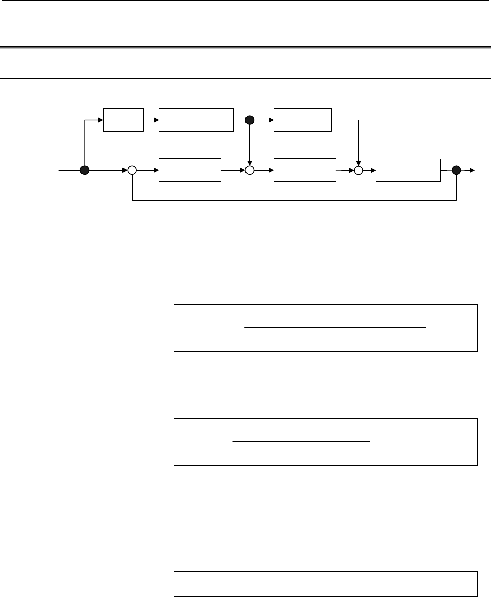
(1) Principle
α
• s
Position gain Velocity loop
+
+
−
Position
command
α
: Feed-forward coefficient (0 to 1)
VFF: Velocity loop feed-forward coefficient
Servo motor
Smoothing VFF • s
+
+
+
Fig. 4.6.1 (a) Feed-forward control block diagram
Adding feed-forward term α to the above servo system causes the
position error to be multiplied by (1 - α).
Feedrate (mm/s)
Position error = × (1 - α)
Minimum detection unit (mm) × position gain
Adding feed-forward term α also causes figure error ∆R1 (mm) due to
a radial delay of the servo system during circular cutting to be
multiplied by (1 - α
2
).
Feedrate
2
(mm/s)
2
∆R1 (mm) = × (1 - α
2
)
2 × position gain
2
× radius (mm)
(Example) If α = 0.7, ∆R1 is reduced to about 1/2.
Beside
∆R1, figure error ∆R2 (mm) may occur in a position command
when an acc./dec. time constant is applied after interpolation for two
axes.
Therefore, total radial figure error
∆R during circular cutting is:
∆R = ∆R1 + ∆R2
This section describes the conventional feed-forward function.
However, when using feed-forward for high-speed and high precision
machining, be sure to use advanced preview feed-forward described in
Subsec. 4.6.2 or RISC feed-forward described in Subsec. 4.6.3.
The shape error in the direction of the radius during circular cutting is
as shown in Fig. 4.6.1 (b) below.
Contents Summary of AC Servo Motor Alpha i/is, Beta is Series Parameter manual
- Page 1FANUC AC SERVO MOTOR @* series FANUC AC SERVO MOTOR #* series PARAMETER MANUAL B-65270EN/05
- Page 2• No part of this manual may be reproduced in any form. • All specifications and designs are subject to change without notice. In this manual we have tried as much as possible to describe all the various matters. However, we cannot describe all the matters which must not be done, or which cannot be
- Page 3B-65270EN/05 DEFINITION OF WARNING, CAUTION, AND NOTE DEFINITION OF WARNING, CAUTION, AND NOTE This manual includes safety precautions for protecting the user and preventing damage to the machine. Precautions are classified into Warning and Caution according to their bearing on safety. Also, supplem
- Page 4
- Page 5B-65270EN/05 TABLE OF CONTENTS TABLE OF CONTENTS DEFINITION OF WARNING, CAUTION, AND NOTE .................................s-1 1 OVERVIEW ............................................................................................. 1 1.1 SERVO SOFTWARE AND SERVO CARDS SUPPORTED BY EACH NC MODEL.....
- Page 6TABLE OF CONTENTS B-65270EN/05 4.1.1 Servo HRV2 Ccontrol ..........................................................................................110 4.2 HIGH-SPEED HRV CURRENT CONTROL ............................................... 114 4.2.1 Servo HRV3 Control .....................................
- Page 7B-65270EN/05 TABLE OF CONTENTS 4.9 SERIAL FEEDBACK DUMMY FUNCTIONS ............................................. 238 4.9.1 Serial Feedback Dummy Functions......................................................................238 4.9.2 How to Use the Dummy Feedback Functions for a Multiaxis Servo Ampl
- Page 8TABLE OF CONTENTS B-65270EN/05 4.18.10 Block Diagrams....................................................................................................353 4.19 SERVO TUNING TOOL SERVO GUIDE................................................... 355 4.19.1 SERVO GUIDE ..................................
- Page 9B-65270EN/05 TABLE OF CONTENTS G.5 HRV1 CONTROL PARAMETERS FOR α SERIES, β SERIES, AND CONVENTIONAL LINEAR MOTORS........................................................ 481 G.6 HRV2 CONTROL PARAMETERS FOR βM SERIES MOTORS................ 490 H DETAILS OF HIGH-SPEED AND HIGH-PRECISION ADJUSTMENT ...
- Page 10
- Page 11B-65270EN/05 1.OVERVIEW 1 OVERVIEW This manual describes the servo parameters of the following NC models using an FANUC AC SERVO MOTOR αi or βi series. The descriptions include the servo parameter start-up and adjustment procedures. The meaning of each parameter is also explained. -1-
- Page 121.OVERVIEW B-65270EN/05 1.1 SERVO SOFTWARE AND SERVO CARDS SUPPORTED BY EACH NC MODEL NC product name Series and edition of applicable servo software Servo card Series 21i-MODEL B (Note1) Series 9096/A(01) and subsequent editions 320C52 servo card Series 0i-MODEL B (Note1) (Supporting i series CNC a
- Page 13B-65270EN/05 1.OVERVIEW NOTE 2 The servo software Series 9096 is compatible with the conventional servo software Series 9090 except for the following function: - Electric gear box (EGB) function can not be used. 3 The servo software Series 90B0 is upwardly compatible with the conventional servo soft
- Page 141.OVERVIEW B-65270EN/05 1.2 ABBREVIATIONS OF THE NC MODELS COVERED BY THIS MANUAL In this manual, the NC product names are abbreviated as follows. NC product name Abbreviations FANUC Series 30i-MODEL A Series 30i-A Series 30i Series 30i FANUC Series 31i-MODEL A Series 31i-A Series 31i FS30i FANUC Se
- Page 15B-65270EN/05 1.OVERVIEW 1.3 RELATED MANUALS The following seven kinds of manuals are available for FANUC AC SERVO MOTOR αi or βi series. In the table, this manual is marked with an asterisk (*). Table 1.3 Related manuals of SERVO MOTOR αi/βi series Document Document name Major contents Major usage n
- Page 161.OVERVIEW B-65270EN/05 Other manufactures’ products referred to in this manual * IBM is registered trademark of International Business Machines Corporation. * MS-DOS and Windows are registered trademarks of Microsoft Corporation. All other product names identified throughout this manual are tradema
- Page 17B-65270EN/05 2. SETTING αiS/αiF/βiS SERIES SERVO PARAMETERS 2 SETTING αiS/αiF/βiS SERIES SERVO PARAMETERS -7-
- Page 182. SETTING αiS/αiF/βiS SERIES SERVO PARAMETERS B-65270EN/05 2.1 INITIALIZING SERVO PARAMETERS 2.1.1 Before Servo Parameter Initialization Before starting servo parameter initialization, confirm the following: <1> NC model (ex.: Series 16i-B) <2> Servo motor model (ex.: αiF8/3000) <3> Pulsecoder buil
- Page 19B-65270EN/05 2. SETTING αiS/αiF/βiS SERIES SERVO PARAMETERS 2.1.2 Parameter Initialization Flow On the servo setting and servo adjustment screens, set the following: In emergency stop state, switch on NC. Initialization bits 00000000 See (2) and (8)-(b)-3 in Subsec. 2.1.3. Motor No. See (3) in Subse
- Page 202. SETTING αiS/αiF/βiS SERIES SERVO PARAMETERS B-65270EN/05 2.1.3 Servo Parameter Initialization Procedure (1) Preparation Switch on the NC in an emergency stop state. Enable parameter writing (PWE = 1). Initialize servo parameters on the servo setting screen. For a Power Mate i with no CRT, specify
- Page 21B-65270EN/05 2. SETTING αiS/αiF/βiS SERIES SERVO PARAMETERS (2) Initialization Start initialization. Do not power off the NC until step (11). #7 #6 #5 #4 #3 #2 #1 #0 INITIAL SET BIT PRMC DGPR PLC0 ( Note) Reset initialization bit 1 to 0. DGPR(#1)=0 After initialization is completed, DGPR (#1) is set
- Page 222. SETTING αiS/αiF/βiS SERIES SERVO PARAMETERS B-65270EN/05 αiS series servo motor Motor Motor ID No. 90D0 90B5 Motor model 90B0 90B1 9096 specification HRV1 HRV2 90E0 90B6 αiS2/5000 0212 162 262 A H A A A αiS2/6000 0218 - 284 G - B B - αiS4/5000 0215 165 265 A H A A A αiS8/4000 0235 185 285 A H A A
- Page 23B-65270EN/05 2. SETTING αiS/αiF/βiS SERIES SERVO PARAMETERS αiS(HV) series servo motor Motor Motor ID No. 90D0 90B5 Motor model 90B0 90B1 9096 specification HRV1 HRV2 90E0 90B6 αiS2/5000HV 0213 163 263 A Q A A D αiS2/6000HV 0219 - 287 G - B B - αiS4/5000HV 0216 166 266 A Q A A D αiS8/4000HV 0236 186
- Page 242. SETTING αiS/αiF/βiS SERIES SERVO PARAMETERS B-65270EN/05 βiS series servo motor Motor Amplifier Motor ID No. 90D0 90B5 Motor model 90B0 90B1 9096 specification driving HRV1 HRV2 90E0 90B6 βiS0.2/5000 0111 4A - 260 A N A A * βiS0.3/5000 0112 4A - 261 A N A A * βiS0.4/5000 0114 20A - 280 A N A A *
- Page 25B-65270EN/05 2. SETTING αiS/αiF/βiS SERIES SERVO PARAMETERS Linear motor Linear motor parameters for servo HRV2 control Note: The following linear motors are driven by 200V. Motor 90D0 90B5 Motor model Motor ID No. 90B0 90B1 9096 specification 90E0 90B6 LiS300A1/4 0441-B200 351 G - B B - LiS600A1/4
- Page 262. SETTING αiS/αiF/βiS SERIES SERVO PARAMETERS B-65270EN/05 Linear motor parameters for servo HRV1 control Motor 90D0 90B5 Motor model Motor ID No. 90B0 90B1 9096 specification 90E0 90B6 LiS1500B1/4 0444-B210 90 A A A A A LiS3000B2/2 0445-B110 91 A A A A A LiS6000B2/2 0447-B110 92 A A A A A LiS9000B
- Page 27B-65270EN/05 2. SETTING αiS/αiF/βiS SERIES SERVO PARAMETERS (5) CMR setting Set CMR, Command Multiply Ratio, it converts the axis movement command into pulses- with the scale of a distance the NC instructs the machine to move. CMR = Command unit / Detection unit CMR 1/2 to 48 Setting value = CMR × 2
- Page 282. SETTING αiS/αiF/βiS SERIES SERVO PARAMETERS B-65270EN/05 Example of setting If the gear reduction ratio between the rotation axis motor and table is 10:1 and the detection unit is 1/1000 degrees The table rotates through 360/10 degrees when the motor makes one turn. The number of position pulses
- Page 29B-65270EN/05 2. SETTING αiS/αiF/βiS SERIES SERVO PARAMETERS (7) Motor rotation direction setting Set the direction in which the motor is to turn when a positive value is specified as a move command. For linear motors, set the parameter according to the description in Section 4.14, "LINEAR MOTOR PARA
- Page 302. SETTING αiS/αiF/βiS SERIES SERVO PARAMETERS B-65270EN/05 Example 1: Parallel type, serial linear scale If the ball screw used in direct coupling has a lead of 10 mm and the separate detector used has a resolution of 0.5 µm per pulse Number of position pulses = 10 / 0.0005 = 20,000 Example 2: Seri
- Page 31B-65270EN/05 2. SETTING αiS/αiF/βiS SERIES SERVO PARAMETERS (9) Reference counter setting Specify the reference counter. The reference counter is used in making a return to the reference position by a grid method. (a) Semi-closed loop Number of position pulses corresponding to a Count on the referen
- Page 322. SETTING αiS/αiF/βiS SERIES SERVO PARAMETERS B-65270EN/05 2622 (FS15i) Reference counter capacity (denominator) 2179 (FS30i, 16i) [Valid data range] 0 to 32767 A value up to around 100 is assumed to be set as the denominator of the reference counter capacity. Note that if a larger value is set, th
- Page 33B-65270EN/05 2. SETTING αiS/αiF/βiS SERIES SERVO PARAMETERS Making these modifications eliminates the difference between the number of position pulses corresponding to a single motor revolution and the reference counter setting. Number of position pulses corresponding to a single motor revolution =
- Page 342. SETTING αiS/αiF/βiS SERIES SERVO PARAMETERS B-65270EN/05 (b) Series30i,15i,16i, 0i,Power Mate i, and so on #7 #6 #5 #4 #3 #2 #1 #0 1815 OPTX ↑To be specified for every NC. OPTX(#1) The separate position detector is: 0: Not to be used 1: To be used NOTE For the Series 30i, 16i, 0i, Power Mate i, a
- Page 35B-65270EN/05 2. SETTING αiS/αiF/βiS SERIES SERVO PARAMETERS 2.1.4 Setting Servo Parameters when a Separate Detector for the Serial Interface is used (1) Overview When a separate detector of the serial output type is used, there is a possibility that the detection unit becomes finer than the detectio
- Page 362. SETTING αiS/αiF/βiS SERIES SERVO PARAMETERS B-65270EN/05 (d) RCN220, RCN223, RCN723, and RCN727 manufactured by Heidenhain Minimum resolution (Note 1) Model Backup 20 HEIDENHAIN 2 pulse/rev RCN220 Not required 223 pulse/rev RCN223, 723 Not required 227 pulse/rev RCN727 Not required NOTE 1 The min
- Page 37B-65270EN/05 2. SETTING αiS/αiF/βiS SERIES SERVO PARAMETERS (Example of parameter setting) [System configuration] • The Series 16i is used. • A linear scale with a minimum resolution of 0.1 µm is used. • The least input increment of the controller is 1 µm. • The amount of movement per motor revoluti
- Page 382. SETTING αiS/αiF/βiS SERIES SERVO PARAMETERS B-65270EN/05 #7 #6 #5 #4 #3 #2 #1 #0 2687 (FS15i) HP2048 2274 (FS30i, 16i) HP2048(#0) The 2048-magnification interpolation circuit (high-resolution serial output circuit H or C) is: 1: To be used 0: Not to be used NOTE This function bit can be used with
- Page 39B-65270EN/05 2. SETTING αiS/αiF/βiS SERIES SERVO PARAMETERS [Number of position pulses] Parameter No. 1891 (Series 15i) or No. 2024 (Series 30i, 16i, and so on) Number of position pulses = Amount of movement per motor revolution [mm] / minimum resolution of the detector [mm] * If the result of the a
- Page 402. SETTING αiS/αiF/βiS SERIES SERVO PARAMETERS B-65270EN/05 (c) Parameter setting for the serial output type rotary encoder * For explanations about the rotary encoders RCN220, RCN223, RCN723, and RCN727 made by Heidenhain, see "Parameter setting for the rotary encoders RCN220, RCN223, RCN723, and R
- Page 41B-65270EN/05 2. SETTING αiS/αiF/βiS SERIES SERVO PARAMETERS [Parameter setting] • To enable a separate detector, set bit 1 of parameter No. 1815 to 1. • Calculate the parameters for the flexible feed gear. Because flexible feed gear (N/M) =360 degrees /0.001 degrees /1,000,000 =36/100 No.2084=36, No
- Page 422. SETTING αiS/αiF/βiS SERIES SERVO PARAMETERS B-65270EN/05 (d) Parameter setting for the rotary encoders RCN220, RCN223, RCN723, and RCN727 made by Heidenhain (Series and editions of applicable servo software) To use high-resolution rotary encoder RCN220, RCN223, RCN723, or RCN727 manufactured by H
- Page 43B-65270EN/05 2. SETTING αiS/αiF/βiS SERIES SERVO PARAMETERS RCNCLR (#1) The number of revolution is: 1: To be cleared. (To use the RCN220, RCN223, RCN723, or RCN727, set the bit to 1.) 0: Not to be cleared. This function bit is to be set in combination with the number of data mask digits, described
- Page 442. SETTING αiS/αiF/βiS SERIES SERVO PARAMETERS B-65270EN/05 [Number of position pulses] Parameter No. 1891 (Series 15i) or No. 2024 (Series 30i, 16i, and so on) Number of position pulses = 100,000×(motor-to-table reduction ratio) * If the result of the above calculation does not fall in the setting
- Page 45B-65270EN/05 2. SETTING αiS/αiF/βiS SERIES SERVO PARAMETERS • Calculate the reference counter capacity. Reference counter capacity = 360 degrees/0.0001 degrees = 3,600,000 (About speed limit) When the RCN223, RCN723, or RCN727 is used as a separate detector, the maximum permissible speed that can be
- Page 462. SETTING αiS/αiF/βiS SERIES SERVO PARAMETERS B-65270EN/05 2.1.5 Setting Servo Parameters when an Analog Input Separate Interface Unit is used (1) Overview An analog input separate interface unit (analog SDU) can be connected directly to an encoder having an analog output signal of 1 Vp-p. This sub
- Page 47B-65270EN/05 2. SETTING αiS/αiF/βiS SERIES SERVO PARAMETERS 2628 (FS15i) Position pulse conversion coefficient (PSMPYL) 2185 (FS30i,16ii) This parameter is used when the calculation result of the number of position pulses is greater than 32767. (Equation for parameter calculation) Set this parameter
- Page 482. SETTING αiS/αiF/βiS SERIES SERVO PARAMETERS B-65270EN/05 2.1.6 Setting Parameters When a CZi Sensor is used (1) Overview CZi sensors may be used in the following two ways: <1> Used as a detector for a synchronous built-in servo motor <2> Used as a separate detector This subsection explains parame
- Page 49B-65270EN/05 2. SETTING αiS/αiF/βiS SERIES SERVO PARAMETERS [Setting flexible feed gear] 1977 (FS15i) Flexible feed gear (numerator) 2084 (FS30i,16i) 1978 (FS15i) Flexible feed gear (denominator) 2085 (FS30i,16i) Set the flexible feed gear according to the equation below. The number of pulses per de
- Page 502. SETTING αiS/αiF/βiS SERIES SERVO PARAMETERS B-65270EN/05 [Parameter setting] AMR=01011000 (88 in decimal representation) Flexible feed gear (N/M) = 360,000/500,000 = 18/25, so parameter No. 2084 = 18, and parameter No. 2085 = 25 Number of velocity pulses = 4096 Number of position pulses = 6235 Re
- Page 51B-65270EN/05 2. SETTING αiS/αiF/βiS SERIES SERVO PARAMETERS [Setting reference counter capacity] 1896 (FS15i) Reference counter capacity 1821 (FS30i,16i) Set the number of pulses per detector (detection unit) or a fraction of the integer value indicating the number of pulses per detector. (Example o
- Page 522. SETTING αiS/αiF/βiS SERIES SERVO PARAMETERS B-65270EN/05 2.1.7 Setting Parameters when the PWM Distribution Module is used (1) Overview The PWM distribution module (PDM) distributes a copy of a PWM command for one axis received from the CNC to more than one servo amplifier. When receiving current
- Page 53B-65270EN/05 2. SETTING αiS/αiF/βiS SERIES SERVO PARAMETERS (2) Series and editions of applicable servo software (Series 16i-B,18i-B,21i-B, Power Mate i) Series 90B1/A(01) and subsequent editions (*) When the PDM is used, it must be supported by the CNC system software. (With the system software ser
- Page 542. SETTING αiS/αiF/βiS SERIES SERVO PARAMETERS B-65270EN/05 #7 #6 #5 #4 #3 #2 #1 #0 2001 (FS16i) 0 AMR6 AMR5 AMR4 AMR3 AMR2 AMR1 AMR0 AMR0 to 6 (#0 to 6) Set the AMR value according to the number of motor poles. AMR Number of motor poles 6 5 4 3 2 1 0 16-pole servo motor 0 0 0 1 0 0 0 αiS2000/2000HV
- Page 55B-65270EN/05 2. SETTING αiS/αiF/βiS SERIES SERVO PARAMETERS 2.1.8 Actions for Illegal Servo Parameter Setting Alarms (1) Overview When a setting value is beyond an allowable range, or when an overflow occurs during internal calculation, an invalid parameter setting alarm is issued. This section expl
- Page 562. SETTING αiS/αiF/βiS SERIES SERVO PARAMETERS B-65270EN/05 (4) Method When an illegal parameter setting alarm detected by the servo software is issued, analyze the cause of the alarm by following the procedure explained below. * When more than one alarm is issued, one of the causes of these alarms
- Page 57B-65270EN/05 2. SETTING αiS/αiF/βiS SERIES SERVO PARAMETERS Table 2.1.8 Detail analysis of illegal parameter setting alarms Parameter No. Alarm Parameter No. (Series 30i, 16i, Cause Action detail No. (Series 15i) and so on) Parameter settings related to Change the parameter settings so 83 - 2008 lea
- Page 582. SETTING αiS/αiF/βiS SERIES SERVO PARAMETERS B-65270EN/05 Parameter No. Alarm Parameter No. (Series 30i, 16i, Cause Action detail No. (Series 15i) and so on) A positive value is not set as the Set a positive value as the flexible 853 1978 2085 flexible feed gear denominator. feed gear denominator.
- Page 59B-65270EN/05 2. SETTING αiS/αiF/βiS SERIES SERVO PARAMETERS Parameter No. Alarm Parameter No. (Series 30i, 16i, Cause Action detail No. (Series 15i) and so on) Keep the setting of this parameter within ±45. Alternatively, set bit 0 of parameter No. 2683 (for the Series 15i) or bit 0 of parameter The
- Page 602. SETTING αiS/αiF/βiS SERIES SERVO PARAMETERS B-65270EN/05 Parameter No. Alarm Parameter No. (Series 30i, 16i, Cause Action detail No. (Series 15i) and so on) The internal value of a parameter 10016 Do not use the runaway detection 1740#0 2200#0 related to runaway detection 10019 function. (Set bit
- Page 61B-65270EN/05 2. SETTING αiS/αiF/βiS SERIES SERVO PARAMETERS Parameter No. Alarm Parameter No. (Series 30i, 16i, Cause Action detail No. (Series 15i) and so on) An axis for which HRV3 is specified This error occurs if the specified exists on the same optical cable. 10113 1707#0 2013#0 current cycle d
- Page 622. SETTING αiS/αiF/βiS SERIES SERVO PARAMETERS B-65270EN/05 Supplementary 2: Control cycle setting There are four different types of control cycle setting (HRV1, HRV2, HRV3, and HRV4). Their settings are explained below. For Series 15i HRV1: No1809=0X000110 HRV2: No1809=0X000011, No1707#0=0 HRV3: No
- Page 63B-65270EN/05 2. SETTING αiS/αiF/βiS SERIES SERVO PARAMETERS (Example of setting) If the linear scale used has a minimum resolution of 0.1 µm and the distance to move per motor turn is 16 mm Set A and B, respectively, to 10000 and 16, because: Ns = distance to move per motor turn (mm)/detector minimu
- Page 642. SETTING αiS/αiF/βiS SERIES SERVO PARAMETERS B-65270EN/05 (ii) If the number of position pulses is larger than 131,000 Change the parameters according to the following table. In this table, letter E satisfies: Number of position feedback pulses/10/E < 13100 Parameter number Method for changing par
- Page 65B-65270EN/05 2. SETTING αiS/αiF/βiS SERIES SERVO PARAMETERS (a) For other than servo software Series 9096 #7 #6 #5 #4 #3 #2 #1 #0 1749 (FS15i) PGAT 2209 (FS16i) PGAT(#6) The position gain precision optimization function is: 1: To be enabled 0: To be disabled (conventional method) NOTE Specify this f
- Page 663. αiS/αiF/βiS SERIES PARAMETER ADJUSTMENT B-65270EN/05 3 αiS/αiF/βiS SERIES PARAMETER ADJUSTMENT This chapter describes parameter tuning for the FANUC AC SERVO MOTOR αiS, αiF, or βiS series. A servo tuning tool, SERVO GUIDE, is available which lets you perform parameter tuning smoothly. See Section
- Page 67B-65270EN/05 3. αiS/αiF/βiS SERIES PARAMETER ADJUSTMENT 3.1 SERVO TUNING SCREEN Display the servo tuning screen, and check the position error, actual current, and actual speed on the screen. Using the keys on the NC, enter values according to the procedure explained below. (The Power Mate i DPL/MDI
- Page 683. αiS/αiF/βiS SERIES PARAMETER ADJUSTMENT B-65270EN/05 <2> <14> <5> <15> <6> <16> <8> <17> <18> <7> Fig. 3.1(c) Series 15i servo tuning screen <9> <19> <10> <20> <11> <21> <12> <22> <13> Fig. 3.1 (d) Series 15i servo diagnosis screen The items on the servo tuning screen correspond to the following
- Page 69B-65270EN/05 3. αiS/αiF/βiS SERIES PARAMETER ADJUSTMENT Table 3.1 Correspondence between the servo tuning screen and diagnosis screen, and parameters Series 15i Series 30i, 16i, and so on <1> Function bit No. 1808 No. 2003 <2> Loop gain No. 1825 No. 1825 <3> Tuning start bit Not used at present <4>
- Page 703. αiS/αiF/βiS SERIES PARAMETER ADJUSTMENT B-65270EN/05 3.2 ACTIONS FOR ALARMS If a servo alarm occurs, detail alarm information is displayed on the diagnosis screen (Figs. 3.1 (b) and (d)). Based on this information, check the cause of the servo alarm and take appropriate action. For alarms with no
- Page 71B-65270EN/05 3. αiS/αiF/βiS SERIES PARAMETER ADJUSTMENT NOTE 1 For alarms with no action number indicated, refer to the Maintenance Manual. 2 OVL = 1, ALD = 1, and EXP = 1 indicate an overheat alarm using DI signals in a linear motor or a synchronous built-in servo motor and are set when bit 7 of pa
- Page 723. αiS/αiF/βiS SERIES PARAMETER ADJUSTMENT B-65270EN/05 Action 2: Overheat alarms If an overheat alarm occurs after long-time continuous operation, the alarm can be determined to have been caused by a temperature rise in the motor or amplifier. Stop operation for a while. If the alarm still occurs a
- Page 73B-65270EN/05 3. αiS/αiF/βiS SERIES PARAMETER ADJUSTMENT (2) Alarms related to the Pulsecoder and separate serial Pulsecoder (2-1) αi Pulsecoder These alarms are identified from alarms 1, 2, 3, and 5. The meanings of the bits are as follows: Alarm 3 Alarm 5 1 Alarm 2 Description Action CSA BLA PHA RC
- Page 743. αiS/αiF/βiS SERIES PARAMETER ADJUSTMENT B-65270EN/05 Action 2: Alarms that may occur due to noise When an alarm occurs intermittently or occurs after emergency stop is released, there is a high possibility that the alarm is caused by noise. Take thorough noise-preventive measures. If the alarm st
- Page 75B-65270EN/05 3. αiS/αiF/βiS SERIES PARAMETER ADJUSTMENT #7 #6 #5 #4 #3 #2 #1 #0 1808 (FS15i) TGAL 2003 (FS30i, 16i) TGAL (#1) 1: The level for detecting the software disconnection alarm is set by parameter. 1892 (FS15i) Software disconnection alarm level 2064 (FS30i, 16i) Standard setting 4: Alarm o
- Page 763. αiS/αiF/βiS SERIES PARAMETER ADJUSTMENT B-65270EN/05 Action 1: This alarm occurs when the move directions for the position detector and velocity detector are opposite to each other. Check the rotation direction of the separate detector. If the direction is opposite to the direction in which the m
- Page 77B-65270EN/05 3. αiS/αiF/βiS SERIES PARAMETER ADJUSTMENT 1971 (FS15i) Dual position feedback conversion coefficient (numerator) 2078 (FS30i, 16i) 1972 (FS15i) Dual position feedback conversion coefficient (denominator) 2079 (FS30i, 16i) Number of feedback pulses per motor revolution (detection unit)
- Page 783. αiS/αiF/βiS SERIES PARAMETER ADJUSTMENT B-65270EN/05 3.3 ADJUSTING PARAMETERS FOR HIGH-SPEED AND HIGH-PRECISION MACHINING 3.3.1 Servo HRV Control Adjustment Procedure (1) Overview For higher positioning precision, higher precision in machined surface and machining profile, shorter machining time,
- Page 79B-65270EN/05 3. αiS/αiF/βiS SERIES PARAMETER ADJUSTMENT The figure below shows the results of a gain adjustment for each servo HRV control type. The figure indicates that improvement in response speed of the current loop by servo HRV control further improves the response speed of velocity control an
- Page 803. αiS/αiF/βiS SERIES PARAMETER ADJUSTMENT B-65270EN/05 (3) Initialization of parameters related to high-speed and high-precision machining The parameter values to be set first before servo adjustments are made are listed below. Sufficient performance can be obtained just by setting these values. Fu
- Page 81B-65270EN/05 3. αiS/αiF/βiS SERIES PARAMETER ADJUSTMENT [Feed-forward and FAD(Fine acc./dec.)] Parameter No. Standard setting FS30i, 16i, Description FS15i value and so on 1951 #6 2007 #6 1 Enables FAD (Fine acc./dec.) (Note 1) 1749 #2 2209 #2 1 Enables FAD of linear type. 1702 2109 16 FAD time cons
- Page 823. αiS/αiF/βiS SERIES PARAMETER ADJUSTMENT B-65270EN/05 [Time Constant] Set the initial value of the time constant of acc./dec. according to the high-speed and high-precision function of the CNC used. Adjust the time constant of acc./dec. to an optimum value while checking the rapid traverse and cut
- Page 83B-65270EN/05 3. αiS/αiF/βiS SERIES PARAMETER ADJUSTMENT (4) Servo HRV control setting Set the type of servo HRV control. The setting of servo HRV2 is always required. So, load the standard parameters for servo HRV2 by following the description given below. Then, set HRV3 or HRV4 as necessary. (For S
- Page 843. αiS/αiF/βiS SERIES PARAMETER ADJUSTMENT B-65270EN/05 (c) Servo HRV4 control After setting servo HRV2 control, set the parameters listed below. Servo HRV4 control and servo HRV3 control cannot be set at the same time. [HRV4 parameters] Parameter No. Recommended Description FS30i value 2014#0 1 Ena
- Page 85B-65270EN/05 3. αiS/αiF/βiS SERIES PARAMETER ADJUSTMENT (a) Adjusting the velocity loop gain and the resonance elimination filter (when Tuning Navigator is used) For adjustment of the resonance elimination filter, Tuning Navigator of SERVO GUIDE can be used. On the main bar of SERVO GUIDE, press the
- Page 863. αiS/αiF/βiS SERIES PARAMETER ADJUSTMENT B-65270EN/05 Under 10dB Under -20dB Wide Tuning Navigator shows bode-plot of velocity loop and you can check the performance of velocity loop. Upper line in bode-plot shows gain characteristic and lower line shows phase characteristic. Important points of t
- Page 87B-65270EN/05 3. αiS/αiF/βiS SERIES PARAMETER ADJUSTMENT (b) Adjusting the velocity loop gain and the resonance elimination filter (when Tuning Navigator is not used) A)Adjustment by torque command waveform 1. Perform rapid traverse with a full stroke of the machine, and observe the torque command wh
- Page 883. αiS/αiF/βiS SERIES PARAMETER ADJUSTMENT B-65270EN/05 NOTE 1 The disturbance elimination filter (see Section 4.5) may be effective. 2 When the resonance elimination filter is used, set a narrow attenuation bandwidth (about 50 Hz or less) and a large damping attenuation factor (about 50% to 80%). 3
- Page 89B-65270EN/05 3. αiS/αiF/βiS SERIES PARAMETER ADJUSTMENT 5. After setting the resonance elimination filter in step 4, measure the torque command again. If there is still vibration left at the same frequency, decrease the damping setting. If vibration occurs at a frequency other than the set frequency
- Page 903. αiS/αiF/βiS SERIES PARAMETER ADJUSTMENT B-65270EN/05 The following graphs show how the time constant in rapid traverse is adjusted. Feedrate Feedrate TCMD TCMD Maximum current Maximum current - 80 -
- Page 91B-65270EN/05 3. αiS/αiF/βiS SERIES PARAMETER ADJUSTMENT [Parameter window main screen] [Acc./dec. + normal control] (7) Adjustment of the position gain Observe the torque command waveform at the time of acc./dec. during rapid traverse and cutting feed at the maximum cutting feedrate. When a low freq
- Page 923. αiS/αiF/βiS SERIES PARAMETER ADJUSTMENT B-65270EN/05 [Parameter window main screen] [Position control] (8) Adjustment by using an arc (adjustment of the feed-forward coefficient and adjustment of the servo function) (a) Feed-forward function For higher precision (higher performance) with small se
- Page 93B-65270EN/05 3. αiS/αiF/βiS SERIES PARAMETER ADJUSTMENT The following figure shows the effect of the feed-forward function. The figure indicates that an arc radius error of 250 µm, which was measured before the use of the feed-forward function, has been reduced to almost 0 after the use of the feed-
- Page 943. αiS/αiF/βiS SERIES PARAMETER ADJUSTMENT B-65270EN/05 (c) Adjusting backlash acceleration To reduce quadrant protrusions (errors generated where the axis move direction is reversed), the backlash acceleration function is used. While observing the quadrant protrusion size, change the backlash accel
- Page 95B-65270EN/05 3. αiS/αiF/βiS SERIES PARAMETER ADJUSTMENT (9) Adjustment by using a square figure (adjustment of the high-speed and high-precision function and adjustment of the servo function) (a) Setting the corner deceleration function When the automatic corner deceleration function is used, an err
- Page 963. αiS/αiF/βiS SERIES PARAMETER ADJUSTMENT B-65270EN/05 (b) Adjusting the time constant in cutting feed In automatic corner deceleration, the feedrate at which the tool moves along a corner is reduced according to the permissible acceleration set for acc./dec. before interpolation. When the automati
- Page 97B-65270EN/05 3. αiS/αiF/βiS SERIES PARAMETER ADJUSTMENT (c) Adjusting velocity feed-forward The velocity feed-forward function has the effect of helping the torque command start earlier at the time of acc./dec. This effect is reflected in corner figures. So, adjust the velocity feed-forward coeffici
- Page 983. αiS/αiF/βiS SERIES PARAMETER ADJUSTMENT B-65270EN/05 (10) Adjustment by using a square figure with 1/4 arcs (adjustment of the high-speed and high-precision function and adjustment of the servo function) When acceleration changes suddenly at an arc part, positional deviation occurs. To reduce thi
- Page 99B-65270EN/05 3. αiS/αiF/βiS SERIES PARAMETER ADJUSTMENT [Parameter window main screen] [Acc./dec. + AI contour control 2 (when AI contour control II is used)] When advanced preview control is used, the feedrate at a rounded portion is suppressed by setting the arc radius and feedrate. For example, w
- Page 1003. αiS/αiF/βiS SERIES PARAMETER ADJUSTMENT B-65270EN/05 The positional deviation in an arc part can be suppressed also by adjusting the velocity feed-forward coefficient. Since the positional deviation in an arc part is caused by velocity loop delay at the start and end of the arc, velocity feed-for
- Page 101B-65270EN/05 3. αiS/αiF/βiS SERIES PARAMETER ADJUSTMENT 3.3.2 High-Speed Positioning Adjustment Procedure (1) Overview This section describes the adjustment procedure for high-speed positioning required with a punch press and PC board drilling machine. (2) Adjustment procedure Make a high-speed posi
- Page 1023. αiS/αiF/βiS SERIES PARAMETER ADJUSTMENT B-65270EN/05 <2> Set a highest possible velocity loop gain according to Subsec. 3.3.1, "Gain Adjustment Procedure." ERR TCM D TCMD fluctuation is eliminated. Fig. 3.3.2(c) After velocity loop gain adjustment <3> Set a switch speed of 1500 (15 min-1) with th
- Page 103B-65270EN/05 3. αiS/αiF/βiS SERIES PARAMETER ADJUSTMENT <5> Make a fine PK1V adjustment to eliminate an overshoot and undershoot. If a large value is set for PK1V, a large undershoot occurs. ERR ERR 20 µm 210 m s TCM D TCMD When the value of PK1V is When the value of PK1V is increased, the amount of
- Page 1043. αiS/αiF/βiS SERIES PARAMETER ADJUSTMENT B-65270EN/05 3.3.3 Rapid Traverse Positioning Adjustment Procedure (1) Overview The fine acc./dec. function applies a filter to each axis in the servo software to reduce a shock associated with acc./dec. By combining the fine acc./dec. function with feed-fo
- Page 105B-65270EN/05 3. αiS/αiF/βiS SERIES PARAMETER ADJUSTMENT (Rapid traverse positioning when fine acc./dec. is used) For further reduction in the time required for rapid traverse positioning, a delay due to position gain needs to be minimized. For this purpose, feed-forward needs to be fully utilized. W
- Page 1063. αiS/αiF/βiS SERIES PARAMETER ADJUSTMENT B-65270EN/05 When the in-position width is 20 pulses, a time of about 180 ms is required from distribution completion to positioning. Reducing this time can speed up positioning. Command from the CNC Positional deviation In-position width Servo delay time o
- Page 107B-65270EN/05 3. αiS/αiF/βiS SERIES PARAMETER ADJUSTMENT <2> Velocity feed-forward adjustment When feed-forward is enabled, the time required for positioning can be reduced, but a swell may occur due to insufficient velocity loop response immediately before machining stops. A swell can be reduced by
- Page 1083. αiS/αiF/βiS SERIES PARAMETER ADJUSTMENT B-65270EN/05 If an adequate feed-forward coefficient is set, the in-position width is satisfied nearly at the same as distribution command completion, and shortest-time positioning is achieved as shown in Fig. 3.3.3 (j). Optimal adjustment in precision and
- Page 109B-65270EN/05 3. αiS/αiF/βiS SERIES PARAMETER ADJUSTMENT 3.3.4 Vibration in the Stop State Vibration generated only in the stop state is caused by the decreased load inertia in a backlash. Adjust the auxiliary functions for suppressing stop-time vibration. Vibration may be generated only in the stop
- Page 1103. αiS/αiF/βiS SERIES PARAMETER ADJUSTMENT B-65270EN/05 Function 3: Function for changing the proportional gain in the stop state #7 #6 #5 #4 #3 #2 #1 #0 1958 (FS15i) PK2VDN 2016 (FS30i, 16i) PK2VDN (#3) 1: Enables the function for changing the proportional gain in the stop state. In the stop state:
- Page 111B-65270EN/05 3. αiS/αiF/βiS SERIES PARAMETER ADJUSTMENT 3.3.5 Vibration during Travel Vibration is generated during travel by various causes. So, a most appropriate method must be selected after observing the vibration status carefully. <1> Is an auxiliary function set to increase the oscillation li
- Page 1123. αiS/αiF/βiS SERIES PARAMETER ADJUSTMENT B-65270EN/05 (Reference: Parameter numbers) For details, see Chapter 4, "Servo Function Details." Function 1: TCMD filter 1895 (FS15i) TCMD filter coefficient 2067 (FS30i, 16i) Function 2: Dual position feedback function #7 #6 #5 #4 #3 #2 #1 #0 1709 (FS15i)
- Page 113B-65270EN/05 3. αiS/αiF/βiS SERIES PARAMETER ADJUSTMENT 1702 (FS15i) Fine acc./dec. time constant 2109 (FS30i, 16i) NOTE In the Series 30i, 31i, and 32i, smooth acc./dec. is always performed by nano interpolation, so the fine acc./dec. function is ignored. - 103 -
- Page 1143. αiS/αiF/βiS SERIES PARAMETER ADJUSTMENT B-65270EN/05 3.3.6 Stick Slip When the time from the detection of a position error until the compensation torque is output is too long, a stick slip occurs during low-speed feed. Improvement in gain is required. However, for a machine with high friction and
- Page 115B-65270EN/05 3. αiS/αiF/βiS SERIES PARAMETER ADJUSTMENT 3.3.7 Overshoot When the machine is operated at high speed or with a detection unit of 0.1 µm or less, the problem of overshoots may arises. Select a most appropriate preventive method depending on the cause of the overshoot. <1> When the veloc
- Page 1164.SERVO FUNCTION DETAILS B-65270EN/05 4 SERVO FUNCTION DETAILS - 106 -
- Page 117B-65270EN/05 4.SERVO FUNCTION DETAILS 4.1 SERVO HRV CONTROL (1) Overview Servo HRV control is a digital servo control system based on high-speed, high-response current control and includes servo HRV1 control, servo HRV2 control, servo HRV3 control, and servo HRV4 control. Use of these control system
- Page 1184.SERVO FUNCTION DETAILS B-65270EN/05 (3) Features of servo HRV control (a) Servo HRV2 control Servo HRV control is a total control technology implemented by a servo motor, servo amplifier, and control systems as shown in the figure below. Servo HRV2 control has the following features: (1) HRV filte
- Page 119B-65270EN/05 4.SERVO FUNCTION DETAILS (c) Servo HRV4 control In addition to the features of servo HRV2 and servo HRV3, servo HRV4 control has the following features: (1) An improved servo HRV control system is employed. (Extended HRV function) (2) Improved thermal resistance in the high-speed DSP an
- Page 1204.SERVO FUNCTION DETAILS B-65270EN/05 4.1.1 Servo HRV2 Ccontrol (1) Series and editions of applicable servo software (Series 30i,31i,32i) Series 90D0/A(01) and subsequent editions Series 90E0/A(01) and subsequent editions (Series 15i-B,16i-B,18i-B,21i-B,0i-B,0i Mate-B, Power Mate i) Series 90B0/A(01
- Page 121B-65270EN/05 4.SERVO FUNCTION DETAILS αiF series servo motor Motor 90D0 90B5 Motor model Motor ID No. 90B0 90B1 specification 90E0 90B6 αiF1/5000 0202 252 A H A A αiF2/5000 0205 255 A H A A αiF4/4000 0223 273 A H A A αiF8/3000 0227 277 A H A A αiF12/3000 0243 293 A H A A αiF22/3000 0247 297 A H A A
- Page 1224.SERVO FUNCTION DETAILS B-65270EN/05 αiS series servo motor Motor Amplifier Motor ID 90D0 90B5 Motor model 90B0 90B1 specification driving No. 90E0 90B6 βiS0.2/5000 0111 4A 260 A N A A βiS0.3/5000 0112 4A 261 A N A A βiS0.4/5000 0114 20A 280 A N A A βiS0.5/5000 0115 20A 281 A N A A βiS0.5/6000 0115
- Page 123B-65270EN/05 4.SERVO FUNCTION DETAILS Linear motor (for 400-V driving) Motor 90D0 90B5 Motor model Motor ID No. 90B0 90B1 specification 90E0 90B6 LiS1500B1/4 0444-B210 358 G - B B LiS3000B2/2 0445-B110 361 G - B B LiS4500B2/2HV 0446-B010 363 G - B B LiS4500B2/2 0446-B110 365 G - B B LiS6000B2/2HV 04
- Page 1244.SERVO FUNCTION DETAILS B-65270EN/05 4.2 HIGH-SPEED HRV CURRENT CONTROL 4.2.1 Servo HRV3 Control (1) Series and editions of applicable servo software (Series 30i,31i,32i) Series 90D0/A(01) and subsequent editions Series 90E0/A(01) and subsequent editions (Series 15i-B,16i-B,18i-B,21i-B,0i-B, Power
- Page 125B-65270EN/05 4.SERVO FUNCTION DETAILS <4> Set the current loop gain magnification. 2747(FS15i) Current loop gain magnification in high-speed HRV current control mode 2334(FS30i,16i) [Unit of data] % [Valid data range] 100 to 270 [Recommended value] 150 This parameter is valid only for cutting feed i
- Page 1264.SERVO FUNCTION DETAILS B-65270EN/05 [Series30i,16i, and so on] High-speed HRV current control mode Feed Velocity loop gain [%] Rapid (1 + No. 2021 / 256) × 100 traverse Set (G5.4Q1 - G5.4Q0) (1 + No. 2021 / 256) × No. 2335 Cutting (High-speed HRV current control: Velocity loop feed gain magnificat
- Page 127B-65270EN/05 4.SERVO FUNCTION DETAILS (Series 90D0, 90E0) The servo amplifiers supporting the Series 30i and so on have advanced thermal resistance. So, unlike Series 90B0, 90B1, 90B6, and 90B5, there is no torque command limitation. (4) Servo HRV3 control hardware (a) Separate detector (Series 90B0
- Page 1284.SERVO FUNCTION DETAILS B-65270EN/05 [Number of controlled axes] When a type A card is used: Up to four servo HRV3 control axes When a type B card is used: Up to eight servo HRV3 control axes • When a type A card is used: Up to four axes plus one unit can be connected. FSSB-1 AMP AMP AMP AMP Separa
- Page 129B-65270EN/05 4.SERVO FUNCTION DETAILS NOTE When 10 or more servo amplifier axes or three separate detector units are used with servo HRV3 control, the Type-B card is required. When 13 or more servo amplifier axes or five separate detector interface units are used without servo HRV3 control, the Type
- Page 1304.SERVO FUNCTION DETAILS B-65270EN/05 4.2.2 Servo HRV4 Control (1) Series and editions of applicable servo software (Series 30i, 31i) Series 90D0/J(10) and subsequent editions (2) Setting parameters for servo HRV4 control <1> See Subsection 4.1.1, and make settings for servo HRV2 control. <2> Set se
- Page 131B-65270EN/05 4.SERVO FUNCTION DETAILS <5> Set the current loop gain magnification. - Current loop gain magnification in high-speed HRV current control mode 2334(FS30i, 31i) [Unit of data] % [Valid data range] 100 to 270 [Recommended value] 150 This parameter is valid only for cutting feed in the hig
- Page 1324.SERVO FUNCTION DETAILS B-65270EN/05 (3) Limitation on servo HRV4 control (a) Servo motor output torque During cutting operation in high-speed HRV current control, the torque command is automatically limited to 70% of the maximum current value of the servo amplifier. As a result, the torque command
- Page 133B-65270EN/05 4.SERVO FUNCTION DETAILS • Numbers of units that can be connected to the servo cards Series 90D0 servo Separate detector Servo card HRV4 control interface unit Servo card B13 A02B-0303-H084 Amplifier 3 axes 1 unit (Type-A card) Servo card B26 A02B-0303-H085 Amplifier 6 axes 2 units (Typ
- Page 1344.SERVO FUNCTION DETAILS B-65270EN/05 4.2.3 High-speed HRV Current Control (1) Starting the high-speed HRV current control mode The high-speed HRV current control mode is turned on and off by using a G code (G5.4). The high-speed HRV current control mode is set for cutting commands specified between
- Page 135B-65270EN/05 4.SERVO FUNCTION DETAILS 4.3 CUTTING/RAPID SWITCHING FUNCTION (1) Overview Increasing the gains of the position loop and velocity loop is effective in the improvement of cutting profiles. However, the maximum feedrate and the acceleration of acc./dec. in rapid traverse are generally hig
- Page 1364.SERVO FUNCTION DETAILS B-65270EN/05 <1> Cutting/rapid velocity loop gain switching function When TCMD is saturated during acceleration in rapid traverse, oscillation is easily generated in the velocity loop at the end of acceleration in rapid traverse. In some machines, as the feedrate becomes hig
- Page 137B-65270EN/05 4.SERVO FUNCTION DETAILS <2> Cutting/rapid fine acc./dec. switching function (including feed-forward switching) Although the optimum time constant of fine acc./dec. during cutting is about 16 ms, the time constant in rapid traverse should sometimes be set to 32 to 40 ms to reduce the im
- Page 1384.SERVO FUNCTION DETAILS B-65270EN/05 (b) Feed-forward, TCMD filter, 1/2 PI current control switching [Series and editions of applicable servo software] (Series 30i,31i,32i) Series 90D0/A(01) and subsequent editions Series 90E0/A(01) and subsequent editions (Series 15i-B,16i-B,18i-B,21i-B,0i-B,0i Ma
- Page 139B-65270EN/05 4.SERVO FUNCTION DETAILS 1895 (FS15i) TCMD filter coefficient 2067 (FS30i,16i) 1779 (FS15i) TCMD filter coefficient for rapid traverse 2156 (FS30i,16i) [Series30i, 16i, and so on] Cutting/rapid feed-forward switching function TCMD filter No. 2156=0 (disabled) Always No. 2067 Rapid trave
- Page 1404.SERVO FUNCTION DETAILS B-65270EN/05 #7 #6 #5 #4 #3 #2 #1 #0 1742 (FS15i) PIAL 2202 (FS30i,16i) 1: Always enables the current loop 1/2 PI control function. [Series30i, 16i, and so on] No. 2203#2=1 No. 2202#1 No. 2202#2 0 0 Always enables the current loop 1/2 PI control function. 1 1 Enables the cur
- Page 141B-65270EN/05 4.SERVO FUNCTION DETAILS 4.4 VIBRATION SUPPRESSION IN THE STOP STATE 4.4.1 Velocity Loop High Cycle Management Function (1) Overview This function improves the velocity loop gain oscillation threshold. This is done by performing velocity loop proportional calculation at high speed, whic
- Page 1424.SERVO FUNCTION DETAILS B-65270EN/05 (4) Performance comparison with the acceleration feedback function Velocity loop high cycle Acceleration feedback function management function Acceleration feedback is performed Only a velocity loop proportional Control method at high speed. calculation is made
- Page 143B-65270EN/05 4.SERVO FUNCTION DETAILS 4.4.2 Acceleration Feedback Function (1) Overview The acceleration feedback function is used to control velocity loop oscillation by using motor speed feedback signal multiplied by the acceleration feedback gain to compensate the torque command. This function ca
- Page 1444.SERVO FUNCTION DETAILS B-65270EN/05 (4) Caution and note CAUTION If the acceleration feedback gain is too large, abnormal sound or vibration can occur during acc./dec. To solve this problem, reduce the gain. NOTE This function is disabled when the velocity loop high cycle management function (see
- Page 145B-65270EN/05 4.SERVO FUNCTION DETAILS 4.4.3 Variable Proportional Gain Function in the Stop State (1) Overview The velocity gain or load inertia ratio is generally increased if a large load inertia is applied to a motor, or to improve the response. An excessively large velocity gain may cause the mo
- Page 1464.SERVO FUNCTION DETAILS B-65270EN/05 #7 #6 #5 #4 #3 #2 #1 #0 1747 (FS15i) PK2D50 2207 (FS30i, 16i) PK2D50 (#3) When the variable proportional gain function in the stop state enabled (K2VDN = 1): 0: The velocity loop proportional gain in the stop state is 75%. 1: The velocity loop proportional gain
- Page 147B-65270EN/05 4.SERVO FUNCTION DETAILS Error Velocity loop proportional gain ( PK2V) 100% Error = + (stop judgement level) Velocity loop Error = 0 proportional gain (PK2V) 75% or 50% Error = − (stop judgement level) Velocity loop proportional gain ( PK2V) 100% Fig. 4.4.3 Relationship between error an
- Page 1484.SERVO FUNCTION DETAILS B-65270EN/05 (d) When the cutting feed/rapid traverse switchable velocity loop gain function (Sec. 4.3) is used, Bit 3 of No. 1958 (Series 15i) or bit 3 of No. 2016 (Series 30i, 16i, and so on) = 1, Bit 3 of No. 1747 (Series 15i) or bit 3 of No. 2207 (Series 30i, 16i, and so
- Page 149B-65270EN/05 4.SERVO FUNCTION DETAILS 4.4.4 N Pulses Suppression Function (1) Overview Even a very small movement of the motor in the stop state may be amplified by a proportional element of the velocity loop, thus resulting in vibration. The N pulse suppression function suppresses this vibration in
- Page 1504.SERVO FUNCTION DETAILS B-65270EN/05 Motor position The function works at this point. N pulse suppression Stop position level parameter Point A (setting standard value is 1 pulse) Point B Torque by proportional element Time Fig. 4.4.4 (b) N pulse suppression function disabled (The N pulse suppressi
- Page 151B-65270EN/05 4.SERVO FUNCTION DETAILS 4.5 MACHINE RESONANCE ELIMINATION FUNCTION 4.5.1 Torque Command Filter (Middle-Frequency Resonance Elimination Filter) (1) Overview The torque command filter applies a primary low-pass filter to the torque command. If the machine resonates at one hundred Hz or o
- Page 1524.SERVO FUNCTION DETAILS B-65270EN/05 Use the torque command filter first when the mechanical system resonates at high frequency. If the resonance cannot be eliminated, use the observer. (5) Setting parameters 1895 (FS15i) Torque command filter (FILTER) 2067 (FS30i, 16i) [Setting value] 1166 (200 Hz
- Page 153B-65270EN/05 4.SERVO FUNCTION DETAILS 4.5.2 Resonance Elimination Filter Function (High-Frequency Resonance Elimination Filter) (1) Overview A filter function for removing high-speed resonance is added. With this function, high-speed resonance can be removed to set a higher velocity loop gain. (2) S
- Page 1544.SERVO FUNCTION DETAILS B-65270EN/05 (4) Setting parameters <1> Setting for resonance elimination filters 2 to 4 The resonance elimination filter has a function for cutting signals of a particular frequency band. Three parameters are used for this filter. They specify the center frequency of a rang
- Page 155B-65270EN/05 4.SERVO FUNCTION DETAILS <2> Setting for resonance elimination filter 1 Only resonance elimination filter 1 has the conventional specification if the damping is 0 and the improved specification if the damping is not 0. 1706 (FS15i) RE filter 1 : Attenuation center frequency 2113 (FS30i,
- Page 1564.SERVO FUNCTION DETAILS B-65270EN/05 For Series 15i Attenuation center Attenuation Damping frequency [Hz] bandwidth Resonance elimination filter 2 No.2773 No.2774 No.2775 Resonance elimination filter 3 No.2776 No.2777 No.2778 Resonance elimination filter 4 No.2779 No.2780 No.2781 Resonance eliminat
- Page 157B-65270EN/05 4.SERVO FUNCTION DETAILS Specify ACREF = 1, and set the center frequency of resonance elimination filter 1 to about (resonance frequency - 30 Hz). Make sure that after the emergency stop is released, resonance is eliminated immediately. If resonance cannot be eliminated immediately, set
- Page 1584.SERVO FUNCTION DETAILS B-65270EN/05 (5) Example of filter characteristics <1> Conventional resonance elimination filter Gain 0 -5 -10 -15 Center frequency = 300 Hz -20 10 1 10 2 10 3 10 4 Bandwidth = 30 Hz Phase Damping = 0 100 50 0 -50 -100 1 2 3 4 10 10 10 10 <2> Improved resonance elimination f
- Page 159B-65270EN/05 4.SERVO FUNCTION DETAILS 4.5.3 Disturbance Elimination Filter Function (Low-Frequency Resonance Elimination Filter) (1) Overview The disturbance elimination filter function estimates a disturbance by comparing a specified torque with the actual velocity, and feeds forward the estimation
- Page 1604.SERVO FUNCTION DETAILS B-65270EN/05 2731 (FS15i) Disturbance elimination filter gain (Kd) 2318 (FS30i, 16i) [Valid data range] 101 to 500 [Typical setting] 500 NOTE If a gain of 0 to 100 is set, the disturbance elimination filter function does not operate. 2732 (FS15i) Inertia ratio (Rj) (%) 2319
- Page 161B-65270EN/05 4.SERVO FUNCTION DETAILS 2735 (FS15i) Acceleration feedback limit (La) 2322 (FS30i, 16i) [Valid data range] 0 to 7282 [Typical setting] 1000 Set a limiter for a feedback torque calculated from acceleration. This parameter suppresses an excessive motion at the time of adjustment. The val
- Page 1624.SERVO FUNCTION DETAILS B-65270EN/05 (3) Set the disturbance elimination filter gain to 500, and check the frequency characteristics with SERVO GUIDE while increasing the gain for inverse model starting with 100 in steps of 100. Adjust the value so that the amplitude of the gain swell part becomes
- Page 163B-65270EN/05 4.SERVO FUNCTION DETAILS 4.5.4 Observer Function (1) Overview The observer is used to eliminate the high-frequency component and to stabilize a velocity loop when a mechanical system resonates at high frequency of several hundred Hertz. The observer is a status observer that estimates t
- Page 1644.SERVO FUNCTION DETAILS B-65270EN/05 The disturbance torque works on the actual motor. There is a time lag in the current loop. The POA1 value does not completely coincide with the actual motor. This is why the motor’s actual velocity differs from the motor speed estimated by an observer. The obser
- Page 165B-65270EN/05 4.SERVO FUNCTION DETAILS 1862 (FS15i) Observer coefficient (POK1) 2050 (FS30i, 16i) • When HRV1, HRV2, or HRV3 is used: [Setting value] Usually, use the standard setting. • When HRV4 is used: [Setting value] 956 → To be changed to 264 1863 (FS15i) Observer coefficient (POK2) 2051 (FS30i
- Page 1664.SERVO FUNCTION DETAILS B-65270EN/05 (7) Stop time observer disable function If the observer function is enabled, the machine may fluctuate and become unstable when it stops. Such a fluctuation or unstable operation can be prevented by disabling the observer function only in the stop state. (8) Set
- Page 167B-65270EN/05 4.SERVO FUNCTION DETAILS 4.5.5 Current Loop 1/2 PI Control Function (1) Overview To improve servo performance in high-speed and high-precision machining, high-speed positioning, ultrahigh-precision positioning, and so forth, a velocity loop gain as high as possible needs to be set stabl
- Page 1684.SERVO FUNCTION DETAILS B-65270EN/05 #7 #6 #5 #4 #3 #2 #1 #0 1742 (FS15i) VGCCR 2202 (FS30i, 16i) VGCCR (#1) 1: To enable the current loop 1/2 PI control function for cutting only (This function is used together with the cutting feed/rapid traverse velocity loop gain switch function.) <3> To enable
- Page 169B-65270EN/05 4.SERVO FUNCTION DETAILS 4.5.6 Vibration Damping Control Function (1) Overview In a closed-loop system, the Pulsecoder on the motor is used for velocity control and a separate detector is used for position control. During acc./dec., the connection between the motor and machine may be di
- Page 1704.SERVO FUNCTION DETAILS B-65270EN/05 (4) Setting parameters 1718 (FS15i) Number of position feedback pulses for vibration damping control 2033 (FS30i, 16i) conversion coefficient [Valid data range] -32767 to 32767 When 0 is set, this function is disabled. If a negative value is specified, it is int
- Page 171B-65270EN/05 4.SERVO FUNCTION DETAILS 4.5.7 Dual Position Feedback Function Optional function (1) Overview A machine with large backlash may cause vibrations in a closed loop system even if it works steadily in a semi–closed loop system. The dual position feedback function controls the machine so th
- Page 1724.SERVO FUNCTION DETAILS B-65270EN/05 (3) Series and editions of applicable servo software (Series 30i,31i,32i) Series 90D0/A(01) and subsequent editions Series 90E0/A(01) and subsequent editions (Series 15i-B,16i-B,18i-B,21i-B,0i-B,0i Mate-B, Power Mate i) Series 9096/A(01) and subsequent editions
- Page 173B-65270EN/05 4.SERVO FUNCTION DETAILS (Example) When the αi Pulsecoder is used with a tool travel of 10 mm/motor revolution (1 µm/pulse) Conversion Numerator 10 × 1000 1 coefficient ( ) = = Denominator 1,000,000 100 1973 (FS15i) Dual position feedback primary delay time constant 2080 (FS30i, 16i) [S
- Page 1744.SERVO FUNCTION DETAILS B-65270EN/05 HBPE (#4) The pitch error compensation is added to the error count of: 1: The semi-closed loop. 0: The closed loop. (Standard setting) #7 #6 #5 #4 #3 #2 #1 #0 1746 (FS15i) HBSF 2206 (FS30i, 16i) HBSF (#4) A backlash compensation and pitch error compensation are:
- Page 175B-65270EN/05 4.SERVO FUNCTION DETAILS Number of position feedback pulses per motor revolution n (Value after multiplication of F⋅FG) Reduce the following fraction: = d 1,000,000 n Is A = 8,000,000 × an integer? d No Yes Obtain the smallest m so that the result of m × A is an integer. Follow the sett
- Page 1764.SERVO FUNCTION DETAILS B-65270EN/05 4.5.8 Machine Speed Feedback Function (1) Overview In many full-closed systems, the machine position is detected by a separate detector and positioning was controlled according to the detected positioning information. The speed is controlled by detecting the mot
- Page 177B-65270EN/05 4.SERVO FUNCTION DETAILS (4) Adding the normalization function (a) Overview If an arc is drawn with the machine speed feedback function enabled, the arc may be elongated in the direction parallel to the axis to which the machine speed feedback function is applied. To solve this problem,
- Page 1784.SERVO FUNCTION DETAILS B-65270EN/05 • Other than flexible feed gear (No. 2084, 2085, 1977, 1978) = 1/1 (Setting range: 101 to 10000 or −101 to −10000) (Typical setting) When the normalization function MCNFB = 3000 to 10000 is not used: When the normalization function MCNFB = −3000 to −10000 is use
- Page 179B-65270EN/05 4.SERVO FUNCTION DETAILS 4.6 CONTOUR ERROR SUPPRESSION FUNCTION 4.6.1 Feed-forward Function (1) Principle α•s Smoothing VFF • s + + + Position Position gain Velocity loop Servo motor command − + + α: Feed-forward coefficient (0 to 1) VFF: Velocity loop feed-forward coefficient Fig. 4.6.
- Page 1804.SERVO FUNCTION DETAILS B-65270EN/05 Start point ∆R2 (Error as a result of acceleration and deceleration after interpolation.) ∆R1 (Error as a result of servo series delay.) Program path Command path Actual path Fig. 4.6.1 (b) Path error during circular cutting (2) Series and editions of applicable
- Page 181B-65270EN/05 4.SERVO FUNCTION DETAILS (3) Setting parameters <1> Enable PI control and the feed-forward function. #7 #6 #5 #4 #3 #2 #1 #0 1808 (FS15i) PIEN 2003 (FS30i, 16i) PIEN (#3) 1: To enable PI control #7 #6 #5 #4 #3 #2 #1 #0 1883 (FS15i) FEED 2005 (FS30i, 16i) FEED (#1) 1: To enable the feed-
- Page 1824.SERVO FUNCTION DETAILS B-65270EN/05 <5> By setting the parameter below, the feed-forward function can be used for cutting feed as well. #7 #6 #5 #4 #3 #2 #1 #0 1800 (FS15i) FFR 1800 (FS30i, 16i) FFR (#3) Specifies whether feed-forward control during rapid traverse is enabled or disabled. 1: Enable
- Page 183B-65270EN/05 4.SERVO FUNCTION DETAILS 4.6.2 Advanced Preview Feed-forward Function (1) Overview The advanced preview feed-forward function is part of the advanced preview control function. It enables high-speed and high precision machining. The function creates feed-forward data according to a comma
- Page 1844.SERVO FUNCTION DETAILS B-65270EN/05 #7 #6 #5 #4 #3 #2 #1 #0 1883 (FS15i) FEED 2005 (FS30i, 16i) FEED (#1) 1: The feed-forward function is enabled. 1962 (FS15i) Velocity feed-forward coefficient (VFFLT) 2069 (FS30i, 16i) [Recommended value] 50 (50 to 200) <2> Set the coefficient for advanced previe
- Page 185B-65270EN/05 4.SERVO FUNCTION DETAILS G code Mode CNC Mode ON Mode OFF G08P1 G08P0 Advanced preview control mode Series 16i, 18i, 21i Acc./dec. mode before look-ahead Series 15i interpolation G05.1Q1 G05.1Q0 AI nano-contour control mode Series 16i, 18i, 21i AI contour control mode Series 16i, 18i, 2
- Page 1864.SERVO FUNCTION DETAILS B-65270EN/05 4.6.3 RISC Feed-forward Function (1) Overview The feed-forward system is used during high precision contour control based on RISC (HPCC mode) or AI contour control (AICC mode) in order to shorten the interpolation cycle, improving the performance of high-speed,
- Page 187B-65270EN/05 4.SERVO FUNCTION DETAILS <3> By specifying a G code in the program, each mode is enabled, and the advanced preview feed-forward function set above is applied. G code Mode Applicable CNC Mode ON Mode OFF G05.1Q1 G05.1Q0 AI contour control mode Series 16i, 18i G05P10000 G05P0 HPCC mode Se
- Page 1884.SERVO FUNCTION DETAILS B-65270EN/05 4.6.4 Cutting/Rapid Feed-forward Switching Function (1) Overview To use a separate feed-forward coefficient for each of cutting feed and rapid traverse, the use of the cutting/rapid fine acc./dec. switching function has been required conventionally. The cutting
- Page 189B-65270EN/05 4.SERVO FUNCTION DETAILS <2> Next, set the cutting/rapid feed-forward switching function. #7 #6 #5 #4 #3 #2 #1 #0 2602 (FS15i) FFCHG 2214 (FS30i, 16i) FFCHG (#4) 1: The cutting/rapid feed-forward switching function is enabled. <3> With the setting of the parameters above, the parameters
- Page 1904.SERVO FUNCTION DETAILS B-65270EN/05 4.6.5 Feed-forward Timing Adjustment Function (1) Overview If the feed-forward function is applied with the aim of decreasing contour errors, the same feed-forward coefficient must be used for all axes. Even if a unified feed-forward coefficient is used, however
- Page 191B-65270EN/05 4.SERVO FUNCTION DETAILS (4) Setting parameters (*1) 1988 (FS15i) Feed-forward timing adjustment coefficient 2095 (FS30i, 16i) Specifying +4096 causes the feed-forward timing to advance by 1 ms. Specifying -4096 causes the feed-forward timing to delay by 1 ms. If you want to decrease th
- Page 1924.SERVO FUNCTION DETAILS B-65270EN/05 4.6.6 Backlash Acceleration Function (1) Overview If the influence of backlash and friction is large in the machine, a delay may be produced on reversal of motor, thus resulting in quadrant protrusion on circular cutting. This is a backlash acceleration function
- Page 193B-65270EN/05 4.SERVO FUNCTION DETAILS #7 #6 #5 #4 #3 #2 #1 #0 1884 (FS15i) FCBL 2006 (FS30i, 16i) FCBL (#0) 1: Do not reflect the backlash compensation in positions. Generally, for a machine in full-closed mode, backlash compensation is not reflected in positions, so this bit is set. (This parameter
- Page 1944.SERVO FUNCTION DETAILS B-65270EN/05 [Example] Example of setting the acceleration amount when a model such as the Series 16i is used Acceleration amount (parameter No. 2048) = 46, acceleration amount override (parameter No. 2114) = 23, limit of acceleration amount (parameter No. 2338) = 500 Backla
- Page 195B-65270EN/05 4.SERVO FUNCTION DETAILS Series 15i Direction-based Reverse Backlash Acceleration Limit of acceleration setting direction acceleration amount amount override amount None Common No. 1860 No. 1725 No .2751 From + to - Present From - to + No. 1987 No. 2753 No. 2754 <5> If a reverse cut occ
- Page 1964.SERVO FUNCTION DETAILS B-65270EN/05 <3> Finally, set the maximum acceleration, and observe the arc figure. If an undercut is generated at the switching point of quadrants, set the acceleration amount limit to prevent the acceleration amount from increasing excessively. • Setting method 2 (strict c
- Page 197B-65270EN/05 4.SERVO FUNCTION DETAILS With following series and editions of servo software, the bit shown below can also be used to enable the backlash acceleration function only during cutting. - Series 90B0/C(03) and subsequent editions - Series 90B6/A(01) and subsequent editions - Series 90B5/A(0
- Page 1984.SERVO FUNCTION DETAILS B-65270EN/05 4.6.7 Two-stage Backlash Acceleration Function (1) Overview When the machine reverses the direction of feed, two types of delay are likely to occur; one type due to friction in the motor and the other due to friction in the machine. The two-stage backlash accele
- Page 199B-65270EN/05 4.SERVO FUNCTION DETAILS (3) Setting parameters <1> With SERVO GUIDE, make settings for measuring the motor speed and estimated disturbance value. (See Sec. 4.19 for SERVO GUIDE.) <2> Turn on the power to the NC. <3> Specify the backlash compensation value. 1851 (FS15i) Backlash compens
- Page 2004.SERVO FUNCTION DETAILS B-65270EN/05 #7 #6 #5 #4 #3 #2 #1 #0 1957 (FS15i) BLAT 2015 (FS30i, 16i) BLAT (#6) 1: To enable the two-stage backlash acceleration function <6> Set the observer-related parameters. The procedure of this adjustment is the same as for an observer-related parameter adjustment
- Page 201B-65270EN/05 4.SERVO FUNCTION DETAILS The procedure for this adjustment is similar to the procedure for adjusting observer-related parameters in the unexpected disturbance torque detection function (Subsection 4.12.1). Make an adjustment by following steps <4> to <7> in (3), "Parameter adjustment me
- Page 2024.SERVO FUNCTION DETAILS B-65270EN/05 1987 (FS15i) First stage acceleration amount from negative direction to positive direction 2094 (FS30i, 16i) (%) [Unit of data] % Normally, this parameter is set to 0. If the quadrant protrusion varies with the reverse direction of the position command in the ma
- Page 203B-65270EN/05 4.SERVO FUNCTION DETAILS Before two-stage backlash acceleration adjustment (A delay in reverse motor rotation causes a protrusion at each area of quadrant switching.) First, set the value of [Typical setting]. Then, while viewing the arc figure, adjust the first stage acceleration amoun
- Page 2044.SERVO FUNCTION DETAILS B-65270EN/05 1982 (FS15i) Second stage end scale factor 2089 (FS30i, 16i) [Unit of data] In units of 0.1 [Valid data range] Series 90B0, 90B6, 90B5, 90D0, 90E0: 0 to 10279 (multiplication by 0 to 1027.9) Series 9096: 0 to 642 (multiplication by 0 to 64.2) [Typical setting] N
- Page 205B-65270EN/05 4.SERVO FUNCTION DETAILS (Second stage acceleration setting in the parameter window) Before start/end parameter adjustment Set the following: Start/end parameter = Value of [Typical setting] Second stage acceleration amount = 500 Then, adjust the start/end parameter while viewing the ti
- Page 2064.SERVO FUNCTION DETAILS B-65270EN/05 NOTE Note that the two-stage backlash acceleration cannot be used together with the backlash stop function. Second stage acceleration is not completed by nature until a distance specified by "Second stage end scale factor" is moved. For example, if only several
- Page 207B-65270EN/05 4.SERVO FUNCTION DETAILS 1790 (FS15i) Second stage offset for two-stage backlash acceleration 2167 (FS30i, 16i) Normally, set 0. Offset for the second stage acceleration amount. See Fig. 4.6.7 (a). The second stage acceleration amount is adjusted to eliminate protrusions and cuts. Befor
- Page 2084.SERVO FUNCTION DETAILS B-65270EN/05 If OVR8 = 1, a = 256 If OVR8 = 0, a = 4096 Here, let α be a circular acceleration, R be a radius (mm), F be a circular feedrate (mm/min), and P be a detection unit (mm). Then, α can be expressed as: 2 α = (F / 60 × 0.008)2 / P R So, the second stage over
- Page 209B-65270EN/05 4.SERVO FUNCTION DETAILS <11>Setting a limit to the second stage acceleration amount Making an optimum override setting for low-speed and high-speed ranges may result in an insufficient acceleration amount in a medium-speed range. To avoid this problem, adjust overriding for low-speed a
- Page 2104.SERVO FUNCTION DETAILS B-65270EN/05 2754 (FS15i) Second stage acceleration limit value for turn-over from the negative 2341 (FS30i, 16i) direction to the positive direction [Valid data range] 0 to 32767 Not used if the two-stage backlash second stage acceleration amount from the negative direction
- Page 211B-65270EN/05 4.SERVO FUNCTION DETAILS By using this bit, switching is enabled even when bit 3 of No. 1800 is set to 1. Backlash acceleration is enabled even at the hole bottom during rigid tapping. #7 #6 #5 #4 #3 #2 #1 #0 2611 (FS15i) BLCUT2 2223 (FS30i, 16i) BLCUT2(#7) 1: The backlash acceleration
- Page 2124.SERVO FUNCTION DETAILS B-65270EN/05 - Comparison with the conventional second stage acceleration Start of reverse operation Conventional second stage acceleration First stage acceleration Second stage acceleration Second stage start position (set in the detection unit) Second stage end position (s
- Page 213B-65270EN/05 4.SERVO FUNCTION DETAILS 1982(FS15i) Second stage end position 2089(FS30i,16i) [Valid data range] 0 to 32767 [Unit od data] Detection unit [Typical setting] 20 to 30 µm NOTE For the 2-stage backlash acceleration function type 2, the second stage end position is set directly in the detec
- Page 2144.SERVO FUNCTION DETAILS B-65270EN/05 4.6.8 Static Friction Compensation Function (1) Overview When a machine, originally in the stop state, is activated, the increase in speed may be delayed by there being a large amount of static friction. The backlash acceleration function (see Subsec. 4.6.6 and
- Page 215B-65270EN/05 4.SERVO FUNCTION DETAILS <2> Set adjustment parameters. 1964 (FS15i) Time during which the static friction compensation function is enabled (in 2071 (FS30i, 16i) 2-ms units) [Valid data range] 0 to 32767 [Recommended value] 10 1965 (FS15i) Static friction compensation 2072 (FS30i, 16i)
- Page 2164.SERVO FUNCTION DETAILS B-65270EN/05 4.6.9 Torsion Preview Control Function (1) Overview For relatively large machines having torsion, torsion occurs between the motor and the machine end during acceleration and deceleration. In machines of this type, positional deviation is caused by torsion durin
- Page 217B-65270EN/05 4.SERVO FUNCTION DETAILS (4) Setting parameters <1> Setting feed-forward Torsion preview control uses feed-forward processing. Therefore, the following parameter must be set: #7 #6 #5 #4 #3 #2 #1 #0 1883(FS15i) FEED 2005(FS16i) FEED(#1) The feed-forward function is: 0: Not used. 1: Used
- Page 2184.SERVO FUNCTION DETAILS B-65270EN/05 <2> Operation measurement and time constant setting To make adjustments, measure the velocity waveform and error amount. The waveform may be measured using either the waveform display screen or SERVO GUIDE. When operating the machine at a feedrate of about F10 m
- Page 219B-65270EN/05 4.SERVO FUNCTION DETAILS <3> Setting the acceleration In torsion preview control, three acceleration areas can be specified, and compensation coefficients can be set separately for these areas. In a machine having the spring characteristic assumed by torsion preview control, there are a
- Page 2204.SERVO FUNCTION DETAILS B-65270EN/05 - LSTAC1 Acceleration that is 3/4 of LSTAC2, 1000 ms taken to reach F12000 mm/min → Acceleration = 12000/60/1 = 200 mm/s2, therefore, LSTAC1 = 2000 - LSTAC3 LSTAC3 = 0 because LSTAC3 is not used. Compensation value Maximum compensation value K2 K1 Acceleration L
- Page 221B-65270EN/05 4.SERVO FUNCTION DETAILS Actual speed 60 45 100 pulses Position =10µm error Fig. 4.6.9(f) Position error at LSTAC1 Set the values measured in Fig. 4.6.9 (e) and Fig. 4.6.9 (f) above in the acceleration torsion compensation values shown below. (Acceleration torsion amount) 2799(FS15i) To
- Page 2224.SERVO FUNCTION DETAILS B-65270EN/05 Compensation value Compensation value Maximum compensation Maximum compensation value value K3 K2 K1 K1 K2 K3 Acceleration Acceleration Acceleration 1 Acceleration 2 Acceleration 3 Acceleration 1 Acceleration 2 Acceleration 3 Fig. 4.6.9(g) Compensation curve whe
- Page 223B-65270EN/05 4.SERVO FUNCTION DETAILS From Fig. 4.6.9 (e) and Fig. 4.6.9 (f), LSTK1 through LSTK3 and LSTK1N through LSTK3N are set as follows: LSTK1=60, LSTK2=100, LSTK3=0 LSTK1N=45, LSTK2N=90, LSTK3N=0 <5> Setting the maximum compensation value (enabling torsion preview control) 2795(FS15i) Torsio
- Page 2244.SERVO FUNCTION DETAILS B-65270EN/05 Compensation for torsion delay Coefficient depending on acceleration Acceleration torsion compensation + + Σ PG Velocity MCMD control TCMD VCMD - Position Position error gain Position FB Fig. 4.6.9(k) Compensation for torsion delay Actual speed Actual speed Posi
- Page 225B-65270EN/05 4.SERVO FUNCTION DETAILS <7> Setting the torsion torque compensation coefficient Torsion torque compensation is set when an adequate velocity loop gain cannot be obtained and acceleration torsion compensation does not work efficiently. The delay in velocity control can be compensated by
- Page 2264.SERVO FUNCTION DETAILS B-65270EN/05 4.7 OVERSHOOT COMPENSATION FUNCTION (1) Setting parameters #7 #6 #5 #4 #3 #2 #1 #0 1808 (FS15i) OVSC 2003 (FS30i, 16i) OVSC (#6) 1: To enable the overshoot compensation function 1857 (FS15i) Velocity loop incomplete integral gain (PK3V) 2045 (FS30i, 16i) [Valid
- Page 227B-65270EN/05 4.SERVO FUNCTION DETAILS + + TCMD PK1V/s Kt/ (Jm • s) VCMD − − Motor PK2V Velocity feedback PK1V: Velocity loop integral gain PK2V: Velocity loop proportional gain /s: Integrator Fig. 4.7 (b) Velocity loop configuration (b) When incomplete integration and overshoot compensation are not
- Page 2284.SERVO FUNCTION DETAILS B-65270EN/05 t0 t1 Move command 1 (MCMD) 1 Position Feedback Speed command Kp (VCMD) Velocity Feedback PK1V × 1 pulse Integrator TCMD1 Friction in the PK1V × 1 pulse machine system TCMD2 Torque command PK1V × 2 pulses (TCMD) Fig. 4.7 (c) Response to 1 pulse movement commands
- Page 229B-65270EN/05 4.SERVO FUNCTION DETAILS (c) Response to 1 pulse movement commands (i) Torque commands for standard settings (when there is no overshoot) Torque command (TCMD) TCMD1 Static friction PK1V × 1 pulse Non-static friction TCMD2 PK2V × 1 pulse Time Fig. 4.7 (d) Torque commands (when there is
- Page 2304.SERVO FUNCTION DETAILS B-65270EN/05 If this overshoot compensation function is used, it is possible to prevent overshoot so that the relationship between machine static and non–static friction and TCMD2 satisfies <1>, however the torque TCMD during machine stop is TCMD2 = 0 the servo rigidity duri
- Page 231B-65270EN/05 4.SERVO FUNCTION DETAILS (4) Improving overshoot compensation for machines using a 0.1-µm detection unit (a) Overview Conventional overshoot compensation performs imperfect integration only when the error is 0. A machine using a 0.1-µm detection unit, however, has a very short period in
- Page 2324.SERVO FUNCTION DETAILS B-65270EN/05 (b) Setting parameters #7 #6 #5 #4 #3 #2 #1 #0 1742 (FS15i) OVS1 2202 (FS30i, 16i) OVS1 (#3) 1: Overshoot compensation is enabled only once after the termination of a move command. Overshoot compensation (Conventional type: When OVS1 = 0) Very small vibration oc
- Page 233B-65270EN/05 4.SERVO FUNCTION DETAILS 4.8 HIGH-SPEED POSITIONING FUNCTION High-speed positioning is used in the following cases: <1> To perform point-to-point movement quickly, where the composite track of two or more simultaneous axes can be ignored such as, for example, in a punch press <2> To spe
- Page 2344.SERVO FUNCTION DETAILS B-65270EN/05 (3) Setting parameters <1> This parameter specifies whether to enable the position gain switching function as follows: #7 #6 #5 #4 #3 #2 #1 #0 1957 (FS15i) PGTW 2015 (FS30i, 16i) PGTW The position gain switching function is used. 1: Valid 0: Invalid <2> This par
- Page 235B-65270EN/05 4.SERVO FUNCTION DETAILS (b) Setting parameters In addition to the parameter of the position gain switching function described earlier, set the following parameter. #7 #6 #5 #4 #3 #2 #1 #0 1744 (FS15i) PGTWN2 2204 (FS30i, 16i) PGTWN2 (#5) Specifies whether to double the feed-forward-bas
- Page 2364.SERVO FUNCTION DETAILS B-65270EN/05 Velocity command When enabled When disabled Positional deviation Position gain Doubled area Fig. 4.8.1 (a) Position gain switching - 226 -
- Page 237B-65270EN/05 4.SERVO FUNCTION DETAILS 4.8.2 Low-speed Integral Function (1) Overview To ensure that the motor responds quickly, a small time constant must be set so that a command enabling quick startup is issued. If the time constant is too small, vibration or hunting occurs because of the delayed
- Page 2384.SERVO FUNCTION DETAILS B-65270EN/05 1715 (FS15i) Limit speed for enabling low-speed integral at deceleration 2030 (FS30i, 16i) The integral gain is validated during deceleration at a speed lower than or equal to the specified speed. [Unit of data] Rotational motor: 0.01 min-1 Linear motor: 0.01 mm
- Page 239B-65270EN/05 4.SERVO FUNCTION DETAILS 4.8.3 Fine Acceleration/Deceleration (FAD) Function (1) Overview The fine acceleration/deceleration (fine acc./dec.) function enables smooth acc./dec. This is done by using servo software to perform acc./dec. processing, which previously has been performed by th
- Page 2404.SERVO FUNCTION DETAILS B-65270EN/05 #7 #6 #5 #4 #3 #2 #1 #0 1749 (FS15i) FADL 2209 (FS30i, 16i) FADL 0: FAD bell-shaped 1: FAD linear type * Set 1 (linear type) usually . NOTE To enable this bit setting, the power must be turned off then back on. 1702 (FS15i) Fine acc./dec. time constant (ms) 2109
- Page 241B-65270EN/05 4.SERVO FUNCTION DETAILS #7 #6 #5 #4 #3 #2 #1 #0 1742 (FS15i) FADCH 2202 (FS30i, 16i) FADCH 1: Enables the fine acc./dec. function, used separately for cutting and rapid traverse. NOTE To enable this bit setting, the power must be turned off then back on. In cutting mode, the following
- Page 2424.SERVO FUNCTION DETAILS B-65270EN/05 Table 4.8.3 Feed-forward coefficient and fine acc./dec. time constant parameters classified by use Series 16i, 18i, 21i, 0i Parameter setting Parameters for cutting Parameters for rapid traverse Position Velocity Position Velocity No. 2005 No. 2007 No. 1800 No.
- Page 243B-65270EN/05 4.SERVO FUNCTION DETAILS (6) Cautions for combined use of fine acc./dec. and rigid tapping CAUTION Because this item was described before the development of the spindle FAD function, part of the description does not match the present situations. When using the spindle FAD function, see
- Page 2444.SERVO FUNCTION DETAILS B-65270EN/05 (Reference) With Series 16i and so on, two types of parameters are available for position gain setting. By setting the parameters as described below, a position gain match can be ensured between the servo axis and spindle. NOTE Do not make following setting when
- Page 245B-65270EN/05 4.SERVO FUNCTION DETAILS (7) Cautions for combined use of the synchronization function with the spindle axis and fine acc./dec. The restrictions listed below are imposed on the combined use of the synchronization function between the servo axis and spindle axis and the fine acc./dec. fu
- Page 2464.SERVO FUNCTION DETAILS B-65270EN/05 (8) Other specifications to note regarding the fine acc./dec. function • Advanced preview control and fine acc./dec. can be used together. (The time constants before and after advanced preview interpolation, and the fine acc./dec. time constant are effective.) •
- Page 247B-65270EN/05 4.SERVO FUNCTION DETAILS (9) Examples of applying the fine acc./dec. function Motor velocity Motor velocity Torque command Torque command Conventional control in which the When the feed-forward function is used feed-forward function is not used Motor velocity Motor velocity Torque comma
- Page 2484.SERVO FUNCTION DETAILS B-65270EN/05 4.9 SERIAL FEEDBACK DUMMY FUNCTIONS 4.9.1 Serial Feedback Dummy Functions (1) Overview The serial feedback dummy functions ignore servo alarms of non-servo axes. (2) Series and editions of applicable servo software (Series 30i,31i,32i) Series 90D0/A(01) and subs
- Page 249B-65270EN/05 4.SERVO FUNCTION DETAILS (4) Handling of dummy axes in the i series CNC Usually in the i series, the number of amplifiers must match that of axes. A dummy axis can be set normally if the axis to be set as the dummy axis has an amplifier. However, if an attempt is made to set an axis tha
- Page 2504.SERVO FUNCTION DETAILS B-65270EN/05 (5) Separate detector-based dummy feedback The separate detector-based dummy feedback function is intended to ignore alarms for an axis when the separate detector has been disconnected from the axis temporarily. Set the following bit. #7 #6 #5 #4 #3 #2 #1 #0 174
- Page 251B-65270EN/05 4.SERVO FUNCTION DETAILS 4.10 BRAKE CONTROL FUNCTION (1) Overview This function prevents the tool from dropping vertically when a servo alarm or emergency stop occurs. The function prevents the motor from being immediately deactivated, instead keeping the motor activated for the period
- Page 2524.SERVO FUNCTION DETAILS B-65270EN/05 NOTE If you want to control the brake for an axis with a two- or three-axis amplifier, specify the brake control parameter for all axes on the multiaxis amplifier including the target axis. If an alarm is generated for any of the axes connected to the two- or th
- Page 253B-65270EN/05 4.SERVO FUNCTION DETAILS <2> Activation delay 1976 (FS15i) Brake control timer 2083 (FS30i, 16i) [Increment system] msec [Valid data range] 0 to 16000 (Example) To specify an activation delay of 200 ms, set the brake control timer usually with 200 (appropriately). Do not set it with 500
- Page 2544.SERVO FUNCTION DETAILS B-65270EN/05 Alarm or emergency stop signal Mechanical brake Servo amplifier MCC off Delay (Td) *ESP signal to PSM (+24 V) The tool drops vertically. Fig. 4.10 (c) Alarm or emergency stop signal 50 to 100 ms (approximately) Mechanical brake Servo amplifier MCC off Brake cont
- Page 255B-65270EN/05 4.SERVO FUNCTION DETAILS 4.11 QUICK STOP FUNCTION The functions described below prevent the tool from colliding with the machine or workpiece by reducing the distance required for the motor to come to a stop if a usual emergency stop condition occurs or if a separate detector disconnect
- Page 2564.SERVO FUNCTION DETAILS B-65270EN/05 (Brake control function) #7 #6 #5 #4 #3 #2 #1 #0 1883 (FS15i) BRKC 2005 (FS30i, 16i) BRKC (#6) Specifies whether to enable brake control function as follows: 1: To enable 0: To disable 1976 (FS15i) Brake control timer 2083 (FS30i, 16i) [Unit of data] ms [Setting
- Page 257B-65270EN/05 4.SERVO FUNCTION DETAILS 4.11.2 Quick Stop Type 2 at Emergency Stop (1) Overview This function returns a servo motor to a position where an emergency stop signal is detected for the servo motor, thereby assuring a shorter stop distance than with quick stop type 1 at emergency stop. Diag
- Page 2584.SERVO FUNCTION DETAILS B-65270EN/05 4.11.3 Lifting Function Against Gravity at Emergency Stop (1) Overview This function is intended to lift and stop the vertical axis (Z-axis) of a vertical machining center when the machine comes to an emergency stop or power failure. (2) Series and editions of a
- Page 259B-65270EN/05 4.SERVO FUNCTION DETAILS NOTE 1 If the brake is in use, it starts working while the vertical axis is being lifted. So the distance through which the axis is actually lifted differs from the setting. 2 Whether the parameter values is positive or negative matches whether the machine coord
- Page 2604.SERVO FUNCTION DETAILS B-65270EN/05 • Motor position waveform Time specified in the brake control timer Distortion easing function: Decreases the machine elastic strain that increases The vertical axis is lifted. when the vertical axis is lifted. The distortion easing function decreases the shock
- Page 261B-65270EN/05 4.SERVO FUNCTION DETAILS It is necessary to specify the time longer than or equal to the brake control timer value. If the brake control timer value is 100 ms, for example, specify ESPTM1 (bit 6) and ESPTM2 (bit 5) to be, respectively, 0 and 1 (100 ms). NOTE For a multiaxis amplifier, t
- Page 2624.SERVO FUNCTION DETAILS B-65270EN/05 NOTE 1 In this example, positive coordinates of the machine coordinate system correspond to the direction in which the axis is lifted. 2 Variation occurs in the position where the Z-axis stops depending on the direction in which the Z-axis is moving before an em
- Page 263B-65270EN/05 4.SERVO FUNCTION DETAILS 4.11.4 Quick Stop Function for Hardware Disconnection of Separate Detector (1) Overview This function reduces the stop distance by resetting the velocity command for a servo motor to 0 when the separate detector for the servo motor encounters a hardware disconne
- Page 2644.SERVO FUNCTION DETAILS B-65270EN/05 NOTE 1 When applying this function to axes under synchronous control (including simple synchronous control), follow the steps below: 1) Change the servo axis setting (No. 1023) for two axes subjected to simple synchronous control so that the two axes can be cont
- Page 265B-65270EN/05 4.SERVO FUNCTION DETAILS 4.11.5 Quick Stop Function at OVL and OVC Alarm (1) Overview This function reduces the stop distance for a servo motor when an OVL (motor overheat or amplifier overheat) or OVC alarm condition is detected for the servo motor. It also causes the other axes to sto
- Page 2664.SERVO FUNCTION DETAILS B-65270EN/05 4.11.6 Overall Use of the Quick Stop Functions To sum up, setting up the following parameters as stated can reduce the stop distance for an emergency stop, separate detector hardware disconnection, and OVL and OVC alarm occurrence. <1> Specify the unexpected dis
- Page 267B-65270EN/05 4.SERVO FUNCTION DETAILS 4.12 UNEXPECTED DISTURBANCE TORQUE DETECTION FUNCTION Optional function 4.12.1 Unexpected Disturbance Torque Detection Function (1) Overview When a tool collides with the machine or workpiece, or when a tool is faulty or damaged, a load torque greater than that
- Page 2684.SERVO FUNCTION DETAILS B-65270EN/05 (3) Parameter adjustment methods <1> Use SERVO GUIDE to observe the motor speed (SPEED) and estimated disturbance torque (DTRQ). (Example of channel settings on SERVO GUIDE) (See Sec. 4.19 for detailed descriptions about how to use the SERVO GUIDE.) <2> Switch o
- Page 269B-65270EN/05 4.SERVO FUNCTION DETAILS Set up the parameters related to the observer. 1862 (FS15i) Observer gain 2050 (FS30i, 16i) • When HRV1, HRV2, or HRV3 control is used: [Standard setting value] 956 → To be changed to 3559. • When HRV4 control is used: [Standard setting value] 264 → To be change
- Page 2704.SERVO FUNCTION DETAILS B-65270EN/05 Make adjustments on the POA1 parameter so that neither an overshoot nor an undershoot will not be observed on the estimated disturbance value at acc./dec. After adjustment, the waveforms shown below should be obtained. (A clear waveform like the one shown below
- Page 271B-65270EN/05 4.SERVO FUNCTION DETAILS <6> For the vertical axis, adjust the torque offset. (This is unnecessary for the horizontal axis.) For the vertical axis, the estimated disturbance value is not centered at level 0. Torque offset adjustment is done to center the estimated disturbance value at l
- Page 2724.SERVO FUNCTION DETAILS B-65270EN/05 If the torque offset parameter is specified, be sure to specify the following parameter also. #7 #6 #5 #4 #3 #2 #1 #0 2603 (FS15i) TCPCLR 2215 (FS30i, 16i) TCPCLR(#1) The function for setting a value for canceling the torque offset at an emergency stop in the ve
- Page 273B-65270EN/05 4.SERVO FUNCTION DETAILS (Example of setting for a rotary motor) - Suppose that the estimated disturbance value at 1000 min-1 is 1 [Ap] (the maximum amplifier current value is 40 [Ap]). Dynamic friction compensation coefficient = 1/40 × 440 = 11 Dynamic friction compensation Dynamic fri
- Page 2744.SERVO FUNCTION DETAILS B-65270EN/05 NOTE This method can be used with the following servo software: (Series 30i, 31i, 32i) Series 90D0/A(01) and subsequent editions Series 90E0/A(01) and subsequent editions (Series 15i-B, 16i-B, 18i-B, 21i-B, 0i-B, 0i Mate-B, Power Mate i) Series 90B0/E(05) and su
- Page 275B-65270EN/05 4.SERVO FUNCTION DETAILS Finally, measure an estimated disturbance value when a movement is made at a maximum feedrate on the axis, then set the results of calculations made according to the table below in "dynamic friction compensation limit value". Dynamic friction |Estimated disturba
- Page 2764.SERVO FUNCTION DETAILS B-65270EN/05 Conceptual diagram illustrating retrace The tool plunges in at full torque. No unexpected disturbance torque detected The tool go beyond slightly, and returns to Unexpected disturbance torque the location where the unexpected detected, but no retrace is performe
- Page 277B-65270EN/05 4.SERVO FUNCTION DETAILS (Series and editions of applicable servo software) (Series 30i,31i,32i) Series 90D0/A(01) and subsequent editions Series 90E0/A(01) and subsequent editions (Series 15i-B,16i-B,18i-B,21i-B,0i-B,0i Mate-B,Power Mate i) Series 90B0/E(05) and subsequent editions Ser
- Page 2784.SERVO FUNCTION DETAILS B-65270EN/05 4.12.2 Cutting/Rapid Unexpected Disturbance Torque Detection Switching Function (1) Overview An alarm threshold for unexpected disturbance torque detection is set separately for cutting and rapid traverse. (2) Series and editions of applicable servo software (Se
- Page 279B-65270EN/05 4.SERVO FUNCTION DETAILS Alarm thresholds for unexpected disturbance torque detection are set in the following parameters: 1997 (FS15i) Unexpected disturbance torque detection threshold for cutting 2104 (FS30i, 16i) (This parameter is used both in not switching mode and in switching mod
- Page 2804.SERVO FUNCTION DETAILS B-65270EN/05 4.13 FUNCTION FOR OBTAINING CURRENT OFFSETS AT EMERGENCY STOP (1) Overview A current offset is an offset value arising from an analog offset voltage associated with an current detector. If such an offset value is not obtained correctly, the feedback current of t
- Page 281B-65270EN/05 4.SERVO FUNCTION DETAILS 4.14 LINEAR MOTOR PARAMETER SETTING 4.14.1 Procedure for Setting the Initial Parameters of Linear Motors (1) Overview The following describes the procedure for setting the digital servo parameters to enable the use of a FANUC linear motor. (2) Series and edition
- Page 2824.SERVO FUNCTION DETAILS B-65270EN/05 Table 4.14.1 (a) Examples of usable linear encoders (incremental) Encoder maker Signal pitch (µm) Model FUTABA 20 FTV, FMV CORPORATION Sony Precision 20 SH12, SH52 Technology Inc. Absolute type The linear encoder of absolute type is directly connected to a servo
- Page 283B-65270EN/05 4.SERVO FUNCTION DETAILS Parameter setting procedure (1) Procedure (1) can be used to initialize the parameters (such as current gain) necessary to drive a linear motor. After initialization, parameters depending on the linear encoder resolution (or the value obtained by dividing the si
- Page 2844.SERVO FUNCTION DETAILS B-65270EN/05 Motor ID number 1874 (FS15i) Motor ID number 2020 (FS30i, 16i) Standard parameters are prepared for the linear motors listed below as of February, 2005. When the standard parameters are not included in the servo software used, see the parameter list shown in thi
- Page 285B-65270EN/05 4.SERVO FUNCTION DETAILS Motor 90B1 90B6 90D0 Motor model Motor ID No. specification 90B8 90B5 90E0 L11000C2/2HVis 0455-B010 387 B(02) B(02) G(07) L11000C2/2is 0455-B110 389 B(02) B(02) G(07) L15000C2/3HVis 0456-B010 391 B(02) B(02) G(07) L10000C3/2is 0457-B110 397 B(02) B(02) G(07) L17
- Page 2864.SERVO FUNCTION DETAILS B-65270EN/05 NOTE 1 With position detection circuit H (A860-0333-T201 or A860-0333-T202), the interpolation magnification can be changed using setting pin SW3. The pin is factory-set to B to set the interpolation magnification to 2048. (When the pin is set to A, the interpol
- Page 287B-65270EN/05 4.SERVO FUNCTION DETAILS #7 #6 #5 #4 #3 #2 #1 #0 1804 (FS15i) PLC0 2000 (FS30i, 16i) PLC0(#0) The number of velocity pulses and the number of position pulses are: 0: Used without being modified. 1: Used after being multiplied by 10 If the number of velocity pulses is lager than 32767, s
- Page 2884.SERVO FUNCTION DETAILS B-65270EN/05 Setting AMR conversion coefficients Calculate the number of feedback pulses per pole-to-pole span of the linear motor, and find AMR conversion coefficients 1 and 2 expressed by the equation shown below. Number of pulses per pole-to-pole span = pole-to-pole span
- Page 289B-65270EN/05 4.SERVO FUNCTION DETAILS [Small motors] (pole-to-pole span: 30mm) Number of velocity pulses / FFG(No.2084/No.2085) AMR conversion PLC0 Number of position pulses, Signal pitch coefficient 1 or 2 0.1-µm (2000#0) Conversion coefficient 1-µm detection (No.2112, 2138) detection (No.2023 / No
- Page 2904.SERVO FUNCTION DETAILS B-65270EN/05 Setting the AMR offset • When the learning control function is used (Series 90B3 and 90B7), see "Learning Function Operator's Manual". • When the learning control function is not used (Series 9096, 90B0, 90B6, 90B5, 90D0, and 90E0), set the AMR offset as follows
- Page 291B-65270EN/05 4.SERVO FUNCTION DETAILS Measuring the activating phase (1) Connect SERVO GUIDE to the CNC, and set channel data as shown below. Select the target axis for measurement, and set the data type to "ROTOR". * For a linear motor, a value from 0 to 360 degrees is read each time a motion is ma
- Page 2924.SERVO FUNCTION DETAILS B-65270EN/05 (3) Set the AMR offset parameter with A (or A - 360). * The parameter setting range is: -45 degrees to +45 degrees (when AMR60 = 0) -60 degrees to +60 degrees (when AMR60 = 1) When the value of A does not lie within the setting range, the installation position o
- Page 293B-65270EN/05 4.SERVO FUNCTION DETAILS (3) For activating phase measurement, set the parameter below. 1726 (FS15i) Parameter for internal data measurement 2115 (FS16i) Series 9096: 326 for an odd-numbered axis and 966 for an even-numbered axis Series 90B0, 90B1, 90B5, or 90B6: 326 for an odd-numbered
- Page 2944.SERVO FUNCTION DETAILS B-65270EN/05 (1) For activating phase adjustment, set the parameter below. • For Series 9096, 90B0, 90B6, 90B5, or 90B1 1726 (FS15i) For internal data measurement 2115 (16i) Series 9096: 320 for an odd-numbered axis, 960 for an even-numbered axis Series 90B0, 90B1, 90B5, or
- Page 295B-65270EN/05 4.SERVO FUNCTION DETAILS (3) Detach the linear motor power line from the servo amplifier, then connect the power line to the DC power supply. Connect the + terminal of the DC power supply to phase U of the power line, and connect the - terminal of the DC power supply to phase V and phas
- Page 2964.SERVO FUNCTION DETAILS B-65270EN/05 (7) Based on activating phase data measured with up to step 6) above, set the AMR offset parameter as described below. * In the description below, the parenthesized values assume AMR60 = 1. When 0 ≤ Value of DGN No. 353 ≤ 32 (42) AMR offset setting = -1 × (value
- Page 297B-65270EN/05 4.SERVO FUNCTION DETAILS (Supplement) Method for checking the activating phase value in the Series 15i The diagnosis screen of the Series 15i has no data that corresponds to No. 353 on the diagnosis screen of the Series 16i and so on. So, display an arbitrary data screen by making the f
- Page 2984.SERVO FUNCTION DETAILS B-65270EN/05 (For Series 30i/31i/32i-A) Refer to the CNC connection manual (B-63943EN). All software series and editions are applicable. (For Series 15i-MB) Refer to the CNC specifications (A-79233E). All software series and editions are applicable. (For Series 16i/18i/21i-B
- Page 299B-65270EN/05 4.SERVO FUNCTION DETAILS - Distance 2 from the scale mark origin to the reference position 1884 (FS30i, 16i) Specify 0. (2) Turn the CNC power off and on again. (3) Follow this procedure to establish a reference position at an appropriate point. Select the JOG mode, and set the manual r
- Page 3004.SERVO FUNCTION DETAILS B-65270EN/05 Parameter setting procedure (5) Procedure (5) can be used to set parameters according to the cooling method used for linear motors. Change the following parameters as listed in Table 4.14.1 (f). For self-cooling linear motors, the parameters need not be set here
- Page 301B-65270EN/05 4.SERVO FUNCTION DETAILS Cooling Rated Model POVC1 POVC2 POVCLMT RTCURR OVCSTP method (N) No cooling 1500 32687 1010 799 658 0 LiS7500B2/4 Water cooling 3000 32446 4026 3197 1316 0 No cooling 1800 32707 758 1199 805 0 LiS9000B2/2 Water cooling 3600 32526 3023 4794 1611 0 No cooling 1800
- Page 3024.SERVO FUNCTION DETAILS B-65270EN/05 Cooling Rated Model POVC1 POVC2 POVCLMT RTCURR OVCSTP method (N) No cooling 1500 32709 739 658 596 0 LiS7500B2/2 Water 3000 32532 2949 2631 1193 0 cooling No cooling 1800 32709 737 947 716 0 LiS9000B2/2 Water 3600 32533 2940 3788 1432 140 cooling No cooling 660
- Page 303B-65270EN/05 4.SERVO FUNCTION DETAILS Cooling Rated Model POVC1 POVC2 POVCLMT RTCURR method (N) No cooling 1800 32729 491 1457 888 9000B/2 Air cooling 2160 32711 707 2098 1065 (160-A driving) Water cooling 3600 32611 1962 5827 1776 No cooling 1800 32737 388 1151 789 9000B/4 Air cooling 2160 32723 55
- Page 3044.SERVO FUNCTION DETAILS B-65270EN/05 Parameter setting procedure (6) Procedure (6) provides supplementary information when servo HRV2 is applied with a conventional linear motor. When initialization has been performed with a motor ID number for servo HRV2 control in procedure (1), parameter setting
- Page 305B-65270EN/05 4.SERVO FUNCTION DETAILS (5) Invalid-parameter alarm when linear motors are used The following invalid-parameter alarm checks are added when linear motors are used (they are not issued for rotational motors). Parameter error alarm Description detail No. No separate detector can be used
- Page 3064.SERVO FUNCTION DETAILS B-65270EN/05 |PK2V parameter| × (load inertia ratio + 256) × 2000 A= Larger than 32767 (Number of velocity pulses) × 64 larger than 32767? Not larger than 32767 B = A × (velocity loop gain override [%] (*1) )/100 Larger than 32767 larger than 32767? Not larger than 32767 Ove
- Page 307B-65270EN/05 4.SERVO FUNCTION DETAILS 4.14.2 Detection of an Overheat Alarm by Servo Software When a Linear Motor and a Synchronous Built-in Servo Motor are Used (1) Overview When a linear motor and a synchronous built-in servo motor are used, the motor overheat signal cannot be posted to the CNC vi
- Page 3084.SERVO FUNCTION DETAILS B-65270EN/05 (2) Series and editions of applicable servo software (Series 15i-B,16i-B,18i-B,21i-B,0i-B,Power Mate i) Series 90B6/B(02) and subsequent editions (Series 0i-C, 20i-B) Series 90B5/B(02) and subsequent editions Although Series 90B1, 90D0, and 90E0 do not support t
- Page 309B-65270EN/05 4.SERVO FUNCTION DETAILS (4) Signals Overheat status signals input via the PMC SVDI61 to SVDI68
#7 #6 #5 #4 #3 #2 #1 #0 G326 SVDI68 SVDI67 SVDI66 SVDI65 SVDI64 SVDI63 SVDI62 SVDI61 [Classification] Input signal [Function] Thermostat signals are input via the PMC. An independent si - Page 3104.SERVO FUNCTION DETAILS B-65270EN/05 4.14.3 Smoothing Compensation for Linear Motor (1) Overview Smoothing compensation for linear motors improves the smoothness in feed of a linear motor by producing a sinusoidal compensation torque with a cycle of 1/2, 1/4, or 1/6 of the pole-to-pole span produce
- Page 311B-65270EN/05 4.SERVO FUNCTION DETAILS Setting the correction gain of the following parameters with a nonzero value can switch between the negative direction smoothing compensation and the positive direction smoothing compensation. In this case, the smoothing compensation parameter explained above ap
- Page 3124.SERVO FUNCTION DETAILS B-65270EN/05 Channel 2: Torque command Select the target axis for measurement, and set "TCMD" as the data type. As the conversion coefficient, set the maximum current of the amplifier used for the target axis. <2> Create a program that performs back and forth motion at a fee
- Page 313B-65270EN/05 4.SERVO FUNCTION DETAILS <6> The compensation parameters slightly vary depending on the measurement situation. So, repeat a data measurement and a press of the [Add] button several times in a similar manner while keeping the dialog box open. (Up to five candidates can be registered.) If
- Page 3144.SERVO FUNCTION DETAILS B-65270EN/05 Activating phase (ROTOR) (Adjustment example) Before smoothing compensation adjustment After smoothing compensation adjustment Torque command (TCMD) (*) For details on the use of SERVO GUIDE, refer to the online help of SERVO GUIDE. If using SD (servo tuning sof
- Page 315B-65270EN/05 4.SERVO FUNCTION DETAILS <2>-a When using A06B-6057-H620 (digital check board), set the DIP switches on the check board as follows: To measure an odd-numbered axis: A06B-6057-H620 CNB CNB CNB CNB CNS Axis 2 Axis 1 Outputs for PIO-48W PC-Card Output to Analog Spindle Input from JA8A CN13
- Page 3164.SERVO FUNCTION DETAILS B-65270EN/05 <4> Start the "SD" software, and make the following setting. DOS prompt > SD INIT [Enter] o (Origin of position) F9 (System setting) 0 (CH0) 2 [Enter] (TCMD) 1.0 [Enter] (1.0A) 1 (CH1) 2 [Enter] (TCMD) 40 [Enter] (Maximum current for servo amplifier to be used)
- Page 317B-65270EN/05 4.SERVO FUNCTION DETAILS TCMD Activating phase angle θ <8> Pressing [CTRL]+[L] causes the correction parameter values to be calculated as shown below. Enter the displayed parameter values. Usually, use the correction parameter values displayed on the top row. The parameter values displa
- Page 3184.SERVO FUNCTION DETAILS B-65270EN/05 When specifying the smoothing compensation (negative direction) parameters (Nos. 2782 to 2784 (Series 15i) or Nos. 2369 to 2371 (Series 16i and so on)), it is impossible to use the parameter values stated on the previous pages without modifying them. It is neces
- Page 319B-65270EN/05 4.SERVO FUNCTION DETAILS (b) Measured waveform where parameter value calculation is impossible (No. 1) Two activating phase angle-based sine waves cannot be acquired because of insufficient measurement time. (c) Measured waveform where parameter value calculation is impossible (No. 2) T
- Page 3204.SERVO FUNCTION DETAILS B-65270EN/05 4.15 TORQUE CONTROL FUNCTION (1) Overview In PMC axis control, the torque control function can be used. The servo motor produces a torque as specified by the NC. Note that the user can switch between position control and torque control. (2) Control types Two typ
- Page 321B-65270EN/05 4.SERVO FUNCTION DETAILS (3) Series and editions of applicable servo software (Series 30i,31i,32i) Series 90D0/A(01) and subsequent editions Series 90E0/A(01) and subsequent editions (Series 15i-B,16i-B,18i-B,21i-B,0i-B,0i Mate-B,Power Mate i) Series 9096/A(01) and subsequent editions S
- Page 3224.SERVO FUNCTION DETAILS B-65270EN/05 #7 #6 #5 #4 #3 #2 #1 #0 1808 (FS15i) PIEN 2003 (FS30i, 16i) PIEN (#3) The velocity control method to be used is: 0: I-P control 1: PI control ← To be set 1998 (FS15i) Torque constant 2105 (FS30i, 16i) This parameter is used to specify a motor-specific torque con
- Page 323B-65270EN/05 4.SERVO FUNCTION DETAILS 4.16 TANDEM DISTURBANCE ELIMINATION CONTROL (POSITION TANDEM) Optional function (1) Overview This function suppresses vibration caused by interference between the main axis and sub-axis in position tandem (simple synchronous or synchronous) control. NC Servo Dis
- Page 3244.SERVO FUNCTION DETAILS B-65270EN/05 (4) Setting parameters Tcmd(M) Velocity fbm Tandem disturbance elimination control 2325(M) Ki 1/s + + Phase compensation + - Kc 2036(S) 2325(S) 2036(M) M : main axis Tcmd(S) S : slave axis Velocity fbs #7 #6 #5 #4 #3 #2 #1 #0 1709 (FS15i) TANDMP 2019 (FS30i, 16i
- Page 325B-65270EN/05 4.SERVO FUNCTION DETAILS 1721 (FS15i) Phase compensation coefficient α 2036 (FS30i, 16i) (Set this parameter for the sub-axis only.) [Valid data range] 51 to 512 (0.1< α <1) [Typical setting] 0 (512 internally) This parameter has the same function as damping compensation of the tandem c
- Page 3264.SERVO FUNCTION DETAILS B-65270EN/05 (5) Adjustment method • Check the torque commands for the main axis and sub-axis and velocity feedback vibration by using a check board. (See Item (6).) • If the vibration phase is shifted by 180 degrees, the cause of resonance is assumed to be inter-axis interf
- Page 327B-65270EN/05 4.SERVO FUNCTION DETAILS (a) Setting parameters related to disturbance input Parameters related to the disturbance input function are set for the sub-axis. (About the disturbance input function) The disturbance input function applies vibration to an axis by inputting a sine wave disturb
- Page 3284.SERVO FUNCTION DETAILS B-65270EN/05 CAUTION 1 Disable the functions that operate only in the stop state, such as the variable proportional gain function in the stop state and the overshoot compensation function. 2 When characteristics at the time of cutting are measured, cutting/rapid switching fu
- Page 329B-65270EN/05 4.SERVO FUNCTION DETAILS (c) Setting for sampling Set the sampling cycle to 250 µs. - 319 -
- Page 3304.SERVO FUNCTION DETAILS B-65270EN/05 (d) Usage When the rising edge of the disturbance input bit (DSTIN) is detected, application of vibration is started. Vibration is automatically stopped after a sine sweep is performed from the start frequency to the end frequency. The operation is stopped by a
- Page 331B-65270EN/05 4.SERVO FUNCTION DETAILS 4.17 SYNCHRONOUS AXES AUTOMATIC COMPENSATION (1) Overview With synchronized axes having a long stroke, a machine twist may occur due to the absolute precision of the scale and thermal expansion of the machine. In such a case, the master motor and slave motor of
- Page 3324.SERVO FUNCTION DETAILS B-65270EN/05 (3) Setting parameters • The following parameters are all set for the slave axis (the axis for which an even number is set in parameter No. 1023) only. #7 #6 #5 #4 #3 #2 #1 #0 2688 (FS15i) ASYN 2275 (FS16i) ASYN (#3) Synchronous axes automatic compensation funct
- Page 333B-65270EN/05 4.SERVO FUNCTION DETAILS 2818 (FS15i) Synchronous axes automatic compensation: Filter coefficient 2405 (FS16i) [Valid data range] 32700 to 32767 [Typical setting] 0 (equivalent to a time constant of 1 second) Set the time constant for reflecting the twist in position compensation. As a
- Page 3344.SERVO FUNCTION DETAILS B-65270EN/05 (4) Application example The figure below shows how synchronous axes automatic compensation works effectively. When the master axis and slave axis, which are synchronized axes connected mechanically, indicate different positions as position B, the master axis and
- Page 335B-65270EN/05 4.SERVO FUNCTION DETAILS 4.18 TORQUE TANDEM CONTROL FUNCTION Optional function (1) Overview If a single motor is not capable of producing sufficient torque to drive a large table, for example, tandem control allows two motors to produce movement along one axis. A motor of the same speci
- Page 3364.SERVO FUNCTION DETAILS B-65270EN/05 Gear Main motor Table Ball screw Sub- motor Fig. 4.18 (b) Example of tandem control application (2) Servo amplifier Servo amplifier FB cable Slider Slider Magnet Fig. 4.18 (c) Example of exercising tandem control (linking linear motors) Power Servo supply amplif
- Page 337B-65270EN/05 4.SERVO FUNCTION DETAILS (3) Start-up procedure To start tandem control, follow the procedure below. Start-up procedure Set tandem axis (See <1> in Sec. 4.18(3)) Set direction of motor rotation (See <2> in Sec. 4.18(3)) Set position feedback (See <3> in Sec. 4.18(3)) Winding tandem? Yes
- Page 3384.SERVO FUNCTION DETAILS B-65270EN/05 1021 (FS15i) Parallel-axis name (for Series 15i only) - Specify 77 and 83 for the main axis and sub-axis, respectively. 1023 (FS15i) Servo axis arrangement 1023 (FS30i, 16i) This parameter specifies servo axis arrangement. Set an odd number for a main axis, and
- Page 339B-65270EN/05 4.SERVO FUNCTION DETAILS <2> Direction of motor rotation 1879 (FS15i) Direction of motor rotation (DIRCT) 2022 (FS30i, 16i) Main axis: With a forward direction specified, 111 specifies that the main axis motor rotates counterclockwise as viewed from the motor shaft side, while -111 spec
- Page 3404.SERVO FUNCTION DETAILS B-65270EN/05 Example of setting The example shown in Fig. 4.18 (a) is used. Assume that the inertia of each section applied to the motor shaft as follows: • Inertias of the reducers of the main- and sub-axes: J1m, J1s • Inertias of the pinions of the main- and sub-axes: J2m,
- Page 341B-65270EN/05 4.SERVO FUNCTION DETAILS 4.18.1 Preload Function By applying an offset to the torque controlled by position (velocity) feedback, torques of opposite directions can be applied to the main- (main motor) and sub-axes (sub-motor) to maintain tension at all times. This function can reduce th
- Page 3424.SERVO FUNCTION DETAILS B-65270EN/05 Torque command Torque limit Main motor +preload Required +preload torque Required torque = −preload (drive torque)/2 (Drive torque)/2 = (main + sub)/2 Sub-motor − Torque limit Fig. 4.18.1 (b) Relationship between required torque and torque command for each motor
- Page 343B-65270EN/05 4.SERVO FUNCTION DETAILS When movement of the table is stopped, check whether the system is in tension. If not, increase this value gradually. WARNING When two motors are not connected, always set a preload value of 0. The sub-axis motor may rotate at extremely high speed, which is very
- Page 3444.SERVO FUNCTION DETAILS B-65270EN/05 4.18.2 Damping Compensation Function To enable more stable tandem control, a torque offset can be applied to the sub-axis, or to both the main- and sub-axes to eliminate a difference in speed, if any, between the main- and sub-axes. This function is particularly
- Page 345B-65270EN/05 4.SERVO FUNCTION DETAILS 1721 (FS15i) Damping compensation gain Kc (ABPGL) 2036 (FS30i, 16i) Set this parameter for the main axis only. [Valid data range] 0 to 32767 [Setting method] Kc × 32768 (0 ≤ Kc < 0.5) A function bit is not supported for the damping compensation function; the dam
- Page 3464.SERVO FUNCTION DETAILS B-65270EN/05 - Adjustment procedure for damping compensation 1 Enable the velocity feedback average function. [No. 1952#2 (Series 15i), No. 2008#2 (Series 30i, 16i, and so on) = 1] 2 Set an adequate preload value. [No. 1980 (Series 15i), No. 2087 (Series 30i, 16i, and so on)
- Page 347B-65270EN/05 4.SERVO FUNCTION DETAILS 4.18.3 Velocity Feedback Average Function As can be seen from the tandem control block diagram shown in Fig. 4.18.10(a) in Subsec. 4.18.10, velocity control is not applied to the sub-axis motor. For this reason, the sub-axis may vibrate and become unstable due t
- Page 3484.SERVO FUNCTION DETAILS B-65270EN/05 Conventionally, however, it was impossible to use "PSM cut-off based on the VRDY OFF alarm invalidation signal" along with the "servo alarm 2-axis simultaneous monitor function." This is because the "servo alarm 2-axis simultaneous monitor function" holds an ala
- Page 349B-65270EN/05 4.SERVO FUNCTION DETAILS #7 #6 #5 #4 #3 #2 #1 #0 1960 (FS15i) PFBCPY 2018 (FS30i, 16i) PFBCPY (#7) 1: The motor feedback signal for the main axis is shared with the sub-axis motor. (Set this parameter for the sub-axis only.) NC Feedback cable Main axis feedback Linear motor Linear motor
- Page 3504.SERVO FUNCTION DETAILS B-65270EN/05 - Servo block diagram (full preload function) Preload (main) > 0 Main Torque + Position command + command Position and Current Motor velocity control + control − Position Rotor feedback position Velocity feedback Motor position feedback Position Machine feedback
- Page 351B-65270EN/05 4.SERVO FUNCTION DETAILS • Preload torque signs to be set when the full preload function is used The polarity of a preload value must always be the same as that of the output torque. So, set the polarities as follows: When SPPCHG = 0 Main-side preload value ≥ 0 Sub-side preload value ≤
- Page 3524.SERVO FUNCTION DETAILS B-65270EN/05 Table 4.18.6(a) Example of setting (1) Synchronous axis Tandem axis Motor name SPPCHG Preload value Main Xm 0 + Master Sub X2 - Main X3 1 - Slave Sub X4 + Another example is given below. Table 4.18.6(b) Example of setting (2) Synchronous axis Tandem axis Motor n
- Page 353B-65270EN/05 4.SERVO FUNCTION DETAILS Tcmd 40 Torque limit 20 Main axis Main axis preload value 0 Sub-axis preload value −20 Sub-axis −40 0 0.2 0.4 0.6 0.8 1 Velocity Time Fig. 4.18.6 (f) Tcmd at acc./dec. time (when the full preload function is used) - 343 -
- Page 3544.SERVO FUNCTION DETAILS B-65270EN/05 4.18.7 Position Feedback Switching Function When the full preload function is enabled, low servo rigidity can result in vibration, as shown in Fig. 4.18.7 (a), only in the case of driving by the sub-axis. In such a case, stable operation can be achieved by using
- Page 355B-65270EN/05 4.SERVO FUNCTION DETAILS - Notes on the position feedback switching function • Reference position return operation and positioning are performed with the main axis only. Note, however, that during movement (command ≠ 0), position feedback on the driving side is used for position control
- Page 3564.SERVO FUNCTION DETAILS B-65270EN/05 NC Main axis motor FB Main motor Sub-axis motor FB Separate FB cable Main axis separate FB Scale Copy Sub motor Sub-axis separate FB Fig. 4.18.7 (d) Full-closed feedback sharing function NOTE Absolute-position communication is not possible with the axis for whic
- Page 357B-65270EN/05 4.SERVO FUNCTION DETAILS 4.18.8 Adjustment (1) Examples of parameter setting This section gives examples of parameter setting. <1> Full-closed loop system using a 1-µm increment system, 8080P/motor revolution for scale feedback, a scale detection unit of 0.5 µm/P, and an α1000i Pulsecod
- Page 3584.SERVO FUNCTION DETAILS B-65270EN/05 <2> Semi-closed loop system using a 1-µ° increment system, rotary axis with a gear reduction ratio of 1/984, and an α64 Pulsecoder (conventional tandem) Series 30i, 16i, and so on Series 15i Main Sub • Tandem axis No. 1817#6 No. 1817#1 1 1 • Semi-closed loop No.
- Page 359B-65270EN/05 4.SERVO FUNCTION DETAILS (2) Back-feed confirmation method “Back-feed” means the feasibility that the axis can be driven not only from motor side but also from machine table side. (a) Check whether back-feed is possible when the machine is connected and the power line is removed. If bac
- Page 3604.SERVO FUNCTION DETAILS B-65270EN/05 (3) Adjustment items If vibration occurs: • Check the position feedback setting (<3> in Sec. 4.18(3)). • With SERVO GUIDE, check VCMD, TCMD, and SPEED. (When using the check board, check Vcmd (CH1), Tcmd (CH2 and CH4), and speed (CH5 and CH6). (a) A higher gear
- Page 361B-65270EN/05 4.SERVO FUNCTION DETAILS 4.18.9 Cautions for Controlling One Axis with Two Motors (1) Tandem control and synchronous control (position tandem control) selection criteria Two control methods are supported to enable the control of one axis using two motors: tandem control and synchronous
- Page 3624.SERVO FUNCTION DETAILS B-65270EN/05 (2) Notes on velocity loop high cycle management (Torque command) Velocity loop high cycle management can be used for tandem control in the following editions: - Series 90B0/A(01) and subsequent editions - Series 90B1/A(01) and subsequent editions - Series 90B6/
- Page 363B-65270EN/05 4.18.10 Preload (main) Torque Velocity command command Command + (1) Tandem control Torque command + + + Position Velocity (main) Current Servo − control control − control amplifier - + Semi-closed loop Velocity feedback Block Diagrams Main 0 motor 1 Full-closed loop + 0 + 1/2 Damping 1
- Page 364Preload (main) Full preload Torque Command command + Torque command + + + + (main) Position Velocity Current Servo control control control amplifier − − + + − Semi-closed loop Velocity feedback Main 0 motor 4.SERVO FUNCTION DETAILS 1 Full-closed + loop 0 + Damping 1 1/2 compensation Scale + − Veloci
- Page 365B-65270EN/05 4.SERVO FUNCTION DETAILS 4.19 SERVO TUNING TOOL SERVO GUIDE 4.19.1 SERVO GUIDE (1) Overview The servo tuning tool SERVO GUIDE has the following features. • PC-based integrated tuning tool for servo spindles • Can be connected easily with a PCMCIA-LAN card from the front of the CNC • GUI
- Page 3664.SERVO FUNCTION DETAILS B-65270EN/05 (2) Operating environment The following table lists operating environments for the servo tuning tool SERVO GUIDE. The operating environment must be configured with the listed hardware and software. Series 30i, 31i, 32i -MODEL A or later Series 16i, 18i, 21i, 20i
- Page 367B-65270EN/05 4.SERVO FUNCTION DETAILS Series 31i-A5 G121/01 and subsequent editions, G131/01 and subsequent editions (SERVO GUIDE Ver. 3.00 or later) Series 32i-A G201/01 and subsequent editions (SERVO GUIDE Ver. 3.00 or later) Series 16i-MB B0H1/05 and subsequent editions Series 16i-TB B1H1/06 and
- Page 3684.SERVO FUNCTION DETAILS B-65270EN/05 For Series 310is, 310is, 320is WindowsCE.NET customized OS A02B-0207-J594 1.2 and subsequent editions WindowsCE.NET FOCAS2/HSSB library A02B-0207-J808 1.2 and subsequent editions WindowsCE.NET standard application/library A02B-0207-J809 1.2 and subsequent editio
- Page 369B-65270EN/05 4.SERVO FUNCTION DETAILS Note 2 It has yet to be verified whether SERVO GUIDE operates on Windows 95. Note 3 To use this software on Windows NT 4.0, install Service Pack 3 or later. Service Pack is available from Microsoft. Note 4 On Windows 98/Me, opening multiple parameter and graph w
- Page 3704.SERVO FUNCTION DETAILS B-65270EN/05 If you are using an HSSB, you may probably use an optical cable to connect between the CNC and PC as shown below. Using SERVO GUIDE does not require any additional connection. * Even if you are using a CNC display unit with PC functions, such as the 160i, no add
- Page 371B-65270EN/05 4.SERVO FUNCTION DETAILS Overshoot improvement Setting for overshoot correction Setting of FAD + advanced preview feed-forward and High-speed positioning position gain line graph Setting related to brake control and quick stop at Stop emergency stop Unexpected disturbance Estimated dist
- Page 3724.SERVO FUNCTION DETAILS B-65270EN/05 (b) Graph window • Data measurement and display - Horizontal axis time mode Ordinary mode, first-order differential mode, second-order differential mode (YT mode) Feed smoothness measurement mode (DXDY mode) Tangential velocity display mode (XTVT mode) Synchroni
- Page 373B-65270EN/05 4.SERVO FUNCTION DETAILS • Linear motor smoothing compensation parameter determination function (Can be used with SERVO GUIDE Ver. 2.00 or later) This function allows easy determination of the parameters for the "smoothing compensation function", which is a function for improving the sm
- Page 3744.SERVO FUNCTION DETAILS B-65270EN/05 (c) Program window • Test program creation assistance - One-axis linear acc./dec. - Arc - Rectangle - Rectangle with rounded corners - Rigid tapping - Cs contour • Test program path display • Sending test programs to NC memory and executing them (The operator mu
- Page 375B-65270EN/05 4.SERVO FUNCTION DETAILS (d) Tuning navigator • Conditions for use SERVO GUIDE Ver. 2.00 or later Servo software Series 90B0/20 and subsequent editions, Series 90B6, Series 90B5, Series 90B1, Series 90D0, Series 90E0 NOTE Series 9096 is not supported. - Automatic tuning of velocity loop
- Page 3764.SERVO FUNCTION DETAILS B-65270EN/05 [High-speed and high-precision function setup support] In a program for a square with corner rounding, the support adjusts the parameters for high-speed and high-precision functions while confirming overshoots. High-speed and high-precision functions have multip
- Page 377B-65270EN/05 5.DETAILS OF PARAMETERS 5 DETAILS OF PARAMETERS - 367 -
- Page 3785.DETAILS OF PARAMETERS B-65270EN/05 5.1 DETAILS OF THE SERVO PARAMETERS FOR Series 30i, 31i, 32i, 15i, 16i, 18i, 21i, 0i, 20i, Power Mate i (SERIES 90D0, 90E0, 90B0, 90B1, 90B6, 90B5, AND 9096) The descriptions of parameters follow. For parameters for which a specification method is not described,
- Page 379B-65270EN/05 5.DETAILS OF PARAMETERS PRMC (#3) Do not change. ( ) PGEX (#4) The position gain range is: 0: Not expanded . 1: Expanded by 8 times. [Reference item] Subsection 2.1.5 #7 #6 #5 #4 #3 #2 #1 #0 1806 (FS15i) 0 AMR6 AMR5 AMR4 AMR3 AMR2 AMR1 AMR0 2001 (FS30i, 16i) AMR0 to ARM7 (#0 to #7) Spec
- Page 3805.DETAILS OF PARAMETERS B-65270EN/05 NPSP (#4) The N pulse suppression function is: 0: Not used. 1: Used. [Reference item] Subsection 4.4.4 [Related parameters] 1992 (15i), 2099 (16i etc.) BLEN (#5) The backlash acceleration function is: 0: Not used. 1: Used. [Reference item] Subsections 4.6.6 and 4
- Page 381B-65270EN/05 5.DETAILS OF PARAMETERS SFCM (#7) The static friction compensation function is: 0: Not used. 1: Used. [Reference item] Subsection 4.6.8 [Related parameters] 1808 (15i), 2003 (16i etc.), 1965 (15i), 2072 (16i etc.), 1966 (15i), 2073 (16i etc.) #7 #6 #5 #4 #3 #2 #1 #0 1884 (FS15i) ACCF PK
- Page 3825.DETAILS OF PARAMETERS B-65270EN/05 #7 #6 #5 #4 #3 #2 #1 #0 1952 (FS15i) LAXDMP PFBSWC VCMDTM SPPCHG SPPRLD VFBAVE TNDM 2008 (FS30i, 16i) TNDM (#1) This bit is automatically set to 1 when bit 6 (tandem axis) of parameter No. 1817 is set to 1. (In the Series 15i, this bit is kept at 0.)This bit cann
- Page 383B-65270EN/05 5.DETAILS OF PARAMETERS ANALOG(#4) Analog servo interface function is: 0: Not used 1: Used [Reference item] Appendix A BLCU(#6) The function that validates the backlash acceleration function only at cutting is: 0: Invalidated. 1: Validated. [Reference item] Subsections 4.6.6 and 4.6.7 B
- Page 3845.DETAILS OF PARAMETERS B-65270EN/05 #7 #6 #5 #4 #3 #2 #1 #0 1955 (FS15i) TMPABS RCCL FFAL EGB 2011 (FS30i, 16i) EGB (#0) The EGB function is: 0: Not used. 1: Used. FFAL (#1) Feed-forward control always is: 1: Enabled in all modes. [Reference item] Subsection 4.6.1 [Related parameters] 1961 (15i), 2
- Page 385B-65270EN/05 5.DETAILS OF PARAMETERS STNG (#7) In velocity command mode, a software disconnection alarm is: 0: Detected. 1: Ignored. #7 #6 #5 #4 #3 #2 #1 #0 1707 (FS15i) APTG HRV3 2013 (FS30i, 16i) HRV3 (#0) HRV3 current control is: 0: Not used. 1: Used. [Reference item] Subsection 4.2.1 APTG (#7) T
- Page 3865.DETAILS OF PARAMETERS B-65270EN/05 BZNG (#7) When a separate detector is used, the battery alarm for the built-in Pulsecoder is: 0: Not ignored. 1: Ignored . #7 #6 #5 #4 #3 #2 #1 #0 1958 (FS15i) PK2VDN ABNT 2016 (FS30i, 16i) ABNT (#0) The unexpected disturbance torque detection function (option) i
- Page 387B-65270EN/05 5.DETAILS OF PARAMETERS #7 #6 #5 #4 #3 #2 #1 #0 1960 (FS15i) PFBCPY OVR8 MOVOBS RVRSE 2018 (FS30i, 16i) RVRSE (#0) The signal direction for the separate detector is: 0: Not reversed. 1: Reversed. Series 90B0 supports the serial type and incremental parallel type. MOVOBS (#1) The disable
- Page 3885.DETAILS OF PARAMETERS B-65270EN/05 ABG0(#3) 1: When an unexpected disturbance torque is detected, a threshold is set separately for cutting and rapid traverse. [Reference item] Subsection 4.12.2 [Related parameters] 1997 (15i), 2104 (16i etc.), 1765 (15i), 2142 (16i etc.) RISCMC (#5) When a RISC p
- Page 389B-65270EN/05 5.DETAILS OF PARAMETERS PIAL (#2) When rapid traverse is selected by the cutting/rapid velocity loop gain switching function, the 1/2 PI control function is: 0: Automatically disabled. 1: Always enabled. [Reference item] Subsection 4.5.5 OVS1 (#3) 1: Overshoot compensation is valid only
- Page 3905.DETAILS OF PARAMETERS B-65270EN/05 DBS2 (#7) Quick stop type 2 at emergency stop is: 0: Not used. 1: Used. [Reference item] Subsection 4.11.2 #7 #6 #5 #4 #3 #2 #1 #0 1745 (FS15i) HDIS HD2O FULDMY 2205 (FS30i, 16i) FULDMY (#2) The dummy separate detector function is: 0: Not used. 1: Used. [Referenc
- Page 391B-65270EN/05 5.DETAILS OF PARAMETERS #7 #6 #5 #4 #3 #2 #1 #0 1749 (FS15i) PGAT FADPGC FADL 2209 (FS30i, 16i) FADL (#2) 0: FAD bell-shaped type 1: FAD linear type [Reference item] Subsection 4.8.3 [Related parameters] 1702 (15i), 2109 (16i etc.) FADPGC (#3) 0: Synchronization is not established in th
- Page 3925.DETAILS OF PARAMETERS B-65270EN/05 #7 #6 #5 #4 #3 #2 #1 #0 2602 (FS15i) FFCHG 2214 (FS30i, 16i) FFCHG (#4) The cutting/rapid feed-forward switching function is: 0: Not used. 1: Used. [Reference item] Subsection 4.6.4 #7 #6 #5 #4 #3 #2 #1 #0 2603 (FS15i) ABT2 TCPCLR 2215 (FS30i, 16i) TCPCLR (#1) A
- Page 393B-65270EN/05 5.DETAILS OF PARAMETERS #7 #6 #5 #4 #3 #2 #1 #0 2613(FS15i) TSA05 TCMD05 2225 (FS30i, 16i) TCMD05 (#1) The check board output voltage of the TCMD signal is: 0: As usual (default). 1: Halved. [Reference item] Appendix I TSA05 (#2) The check board output voltage of the SPEED signal is: 0:
- Page 3945.DETAILS OF PARAMETERS B-65270EN/05 #7 #6 #5 #4 #3 #2 #1 #0 2686 (FS15i) DBTLIM EGBFFG EGBEX POA1NG WSVCP 2273 (FS30i, 16i) WSVCP (#0) When the simple synchronous control is used, the loop integrator of the master axis : 0: Can not be copied to the slave axis. 1: Can be copied to the slave axis. (S
- Page 395B-65270EN/05 5.DETAILS OF PARAMETERS RCNCLR (#1) The speed data is: 0: Not cleared. 1: Cleared. (To use the RCN223 or RCN723, set it to 1.) [Reference item] Subsection 2.1.4 [Related parameters] 2807 (15i), 2394 (16i etc.) ASYN (#3) Synchronous axes automatic compensation function is: 0: Disabled. 1
- Page 3965.DETAILS OF PARAMETERS B-65270EN/05 ☆: Parameters set up automatically at initialization ★: Parameters that can be kept at the automatically set values Parameter number Series 30i, 16i, Details Series 15i and so on 1896 1821 Reference counter capacity →2.1.3 1825 1825 Position loop gain (position g
- Page 397B-65270EN/05 5.DETAILS OF PARAMETERS ☆: Parameters set up automatically at initialization ★: Parameters that can be kept at the automatically set values Parameter number Series 30i, 16i, Details Series 15i and so on Current dead-band compensation (PDDP) 1866 2054 ★ Motor-specific The standard settin
- Page 3985.DETAILS OF PARAMETERS B-65270EN/05 ☆: Parameters set up automatically at initialization ★: Parameters that can be kept at the automatically set values Parameter number Series 30i, 16i, Details Series 15i and so on 1990 2097 Static friction compensation stop parameter ☆ → 4.6.8 1991 2098 Current ph
- Page 399B-65270EN/05 5.DETAILS OF PARAMETERS ☆: Parameters set up automatically at initialization ★: Parameters that can be kept at the automatically set values Parameter number Series 30i, 16i, Details Series 15i and so on 1769 2146 Two-stage backlash acceleration end timer → 4.6.7 Deceleration decision le
- Page 4005.DETAILS OF PARAMETERS B-65270EN/05 ☆: Parameters set up automatically at initialization ★: Parameters that can be kept at the automatically set values Parameter number Series 30i, 16i, Details Series 15i and so on 2-stage backlash acceleration function : stage-2 acceleration 2752 2339 →4.6.7 amoun
- Page 401B-65270EN/05 5.DETAILS OF PARAMETERS ☆: Parameters set up automatically at initialization ★: Parameters that can be kept at the automatically set values Parameter number Series 30i, 16i, Details Series 15i and so on 2804 2391 Torsion preview control: acceleration torsion compensation →4.6.9 value K1
- Page 4026.PARAMETER LIST B-65270EN/05 6 PARAMETER LIST - 392 -
- Page 403B-65270EN/05 6.PARAMETER LIST 6.1 PARAMETERS FOR HRV1 CONTROL Februay, 2005 Series 9096 Series 90B0 - 393 -
- Page 4046.PARAMETER LIST B-65270EN/05 LiS1500B1 LiS3000B2 LiS6000B2 LiS9000B2 LiS15000C2 LiS3000B2 LiS6000B2 LiS9000B2 LiS15000C2 LiS300A1 LiS600A1 Motor model /4 /2 /2 /2 /2 /4 /4 /4 /3 /4 /4 Motor 444-B210 445-B110 447-B110 449-B110 456-B110 445-B210 447-B210 449-B210 456-B210 441-B200 442-B200 specificat
- Page 405B-65270EN/05 6.PARAMETER LIST LiS900A1 LiS6000B2 LiS9000B2 LiS9000B2 LiS15000C2 Motor model /4 /4 /2 /4 /2 Motor 443-B200 (160A) (160A) (360A) (360A) specification Motor ID No. 126 127 128 129 130 Symbol FS15i FS16i,etc 1808 2003 00001000 00001000 00001000 00001000 00001000 1809 2004 00000110 000001
- Page 4066.PARAMETER LIST B-65270EN/05 Motor model βiS2 αiF1 βiS2 β2is αiF2 βiS4 β4iS βiS8 β8iS α2iS α2iS 4000HV 5000 4000 SVPM40A 5000 4000 SVPM40A 3000 SVPM40A 5000 5000HV Motor 0062 0202 0061 0061 0205 0063 0063 0075 0075 0212 0213 specification Motor ID No. 151 152 153 154 155 156 157 158 159 162 163 Sym
- Page 407B-65270EN/05 6.PARAMETER LIST β4iS α4iS α4iS β8iS β12iS αC4 β12iS α4iF βiS22 αiF4 αC8 Motor model 4000HV 5000 5000HV 3000HV 3000HV 3000i 3000 4000 2000 4000HV 2000i Motor 0064 0215 0216 0076 0079 0221 0078 0223 0085 0225 0226 specification Motor ID No. 164 165 166 167 170 171 172 173 174 175 176 Sym
- Page 4086.PARAMETER LIST B-65270EN/05 α8iF β22iS α8iF β0.5iS β1iS α8iS α8iS α12iS α12iS αC12 α12iF Motor model 3000 2000HV 3000HV 6000 6000 4000 4000HV 4000 4000HV 2000i 3000 Motor 0227 0086 0229 0115 0116 0235 0236 0238 0239 0241 0243 specification Motor ID No. 177 178 179 181 182 185 186 188 189 191 193 S
- Page 409B-65270EN/05 6.PARAMETER LIST Motor model α12iF αC22 α22iF α22iF αC30 α30iF α40iF α40iF α22iS α22iS α30iS 3000HV 2000i 3000 3000HV 1500i 3000 3000 3000 Fan 4000 4000HV 4000 Motor 0245 0246 0247 0249 0251 0253 0257 0258 0265 0266 0268 specification Motor ID No. 195 196 197 199 201 203 207 208 215 216
- Page 4106.PARAMETER LIST B-65270EN/05 α30iS α40iS α40iS α50iS α50iS α50iS α50iS α100iS α100iS α200iS α200iS Motor model 4000HV 4000 4000HV 3000 3000 Fan 3000HV Fan 3000HV 2500 2500HV 2500 2500HV Motor 0269 0272 0273 0274 0275 0276 0277 0285 0286 0288 0289 specification Motor ID No. 219 222 223 224 225 226 2
- Page 411B-65270EN/05 6.PARAMETER LIST α300iS α500iS α500iS α1000iS Motor model 2000HV 2000 2000HV 2000HV Motor 0293 0295 0296 0298 specification Motor ID No. 243 245 246 248 Symbol FS15i FS16i,etc 1808 2003 00001000 00001000 00001000 00001000 1809 2004 01000110 00000110 01000110 01000110 1883 2005 00000000
- Page 4126.PARAMETER LIST B-65270EN/05 6.2 PARAMETERS FOR HRV2 CONTROL Februay, 2005 Series 90B0 Series 90B6, 90B5 Series 90D0, 90E0 - 402 -
- Page 413B-65270EN/05 6.PARAMETER LIST Motor model β2iS α1iF β2iS β2iS α2iF β4iS β4iS β8iS β8iS β0.2iS β0.3iS 4000HV 5000 4000 SVPM40A 5000 4000 SVPM40A 3000 SVPM40A 5000 5000 Motor 0062 0202 0061 0061 0205 0063 0063 0075 0075 0111 0112 specification Motor ID No. 251 252 253 254 255 256 257 258 259 260 261 S
- Page 4146.PARAMETER LIST B-65270EN/05 α2iS α2iS β4iS α4iS α4iS β8iS β12iS αC4 β12iS α4iF β22iS Motor model 5000 5000HV 4000HV 5000 5000HV 3000HV 3000HV 3000i 3000 4000 2000 Motor 0212 0213 0064 0215 0216 0076 0079 0221 0078 0223 0085 specification Motor ID No. 262 263 264 265 266 267 270 271 272 273 274 Sym
- Page 415B-65270EN/05 6.PARAMETER LIST Motor model α4iF αC8 α8iF β22iS α8iF β0.4iS β0.5iS β1iS α2iS α8iS α8iS 4000HV 2000i 3000 2000HV 3000HV 5000 6000 6000 6000 4000 4000HV Motor 0225 0226 0227 0086 0229 0114 0115 0116 0218 0235 0236 specification Motor ID No. 275 276 277 278 279 280 281 282 284 285 286 Sym
- Page 4166.PARAMETER LIST B-65270EN/05 α2iS α12iS α12iS α8iS αC12 α8iS α12iF α12iF αC22 α22iF α22iF Motor model 6000HV 4000 4000HV 6000 2000i 6000HV 3000 3000HV 2000i 3000 3000HV Motor 0219 0238 0239 0232 0241 0233 0243 0245 0246 0247 0249 specification Motor ID No. 287 288 289 290 291 292 293 295 296 297 29
- Page 417B-65270EN/05 6.PARAMETER LIST Motor model αC30 α30iF α40iF α40iF α22iS α22iS α30iS α30iS α40iS α40iS α50iS 1500i 3000 3000 3000 Fan 4000 4000HV 4000 4000HV 4000 4000HV 3000 Motor 0251 0253 0257 0258 0265 0266 0268 0269 0272 0273 0274 specification Motor ID No. 301 303 307 308 315 316 318 319 322 323
- Page 4186.PARAMETER LIST B-65270EN/05 α50iS α50iS α50iS α100iS α100iS α200iS α200iS α2000iS α300iS α300iS α500iS Motor model 3000 Fan 3000HV Fan 3000HV 2500 2500HV 2500 2500HV 2000HV 2000 2000HV 2000 Motor 0275 0276 0277 0285 0286 0288 0289 0290 0292 0293 0295 specification Motor ID No. 325 326 327 335 336
- Page 419B-65270EN/05 6.PARAMETER LIST α500iS α1000iS Motor model 2000HV 2000HV Motor 0296 0298 specification Motor ID No. 346 348 Symbol FS15i FS30i,16i,etc 1808 2003 00001000 00001000 1809 2004 01000011 01000011 1883 2005 00000000 00000000 1884 2006 00000000 00000000 1951 2007 00000000 00000000 1952 2008 0
- Page 4206.PARAMETER LIST B-65270EN/05 Motor model i L S300A1/4 i L SL600A1/4 i L S900A1/4 i L S1500B1/4 i L S1500B1/4 i L S3000B2/2 i L S3000B2/2 i L S3000B2/4 i L S4500B2 i L S4500B2/2 i L S4500B2/2 (200V) (200V) (200V) (200V) (400V) (200V) (400V) (200V) /2HV(400V) (200V) (400V) Motor 0441-B200 0442-B200 0
- Page 421B-65270EN/05 6.PARAMETER LIST Motor model i L S6000B2 i i i L S6000B2/2 L S6000B2/2 L S6000B2/4 i L S7500B2 i i i i i i L S7500B2/2 L S7500B2/2 L S7500B2/4 L S9000B2/2 L S9000B2/2 L S9000B2/4 /2HV(400V) (200V) (400V) (200V) /2HV(400V) (200V) (400V) (200V) (200V) (400V) (200V) Motor 0447-B010 0447-B1
- Page 4226.PARAMETER LIST B-65270EN/05 Motor model i i i i L S3300C1/2 L S3300C1/2 L S9000C2/2 L S9000C2/2 i i i i i i i L S11000C2 L S11000C2/2 L S11000C2/2 L S15000C2 L S15000C2/2 L S15000C2/3 L S10000C3/2 (200V) (400V) (200V) (400V) /2HV(400V) (200V) (400V) /3HV(400V) (200V) (200V) (200V) Motor 0451-B110
- Page 423B-65270EN/05 6.PARAMETER LIST Motor model i i i L S10000C3/2 L S17000C3/2 L S17000C3/2 (400V) (200V) (400V) Motor 0457-B110 0459-B110 0459-B110 specification Motor ID No. 397 400 401 Symbol FS15i FS30i,16i,etc 1808 2003 00001000 00001000 00001000 1809 2004 00000011 00000011 00000011 1883 2005 000000
- Page 4246.PARAMETER LIST B-65270EN/05 6.3 PARAMETERS FOR HRV1 CONTROL (FOR Series 0i-A) August, 2003 9066 series (Series 0i-A) NOTE The parameters listed below cannot be loaded automatically. In parameter No. 2020 for entering a motor ID number, enter an appropriate number (15, for example), and perform aut
- Page 425B-65270EN/05 6.PARAMETER LIST Motor α1iF α2iF αC4 α4iF α4iF αC8 α8iF α8iF βM0.5 βM1 αC12 i α12 F model 5000 5000 3000i 4000 4000HV 2000i 3000 3000HV 2000i 3000 Motor 0202 0205 0221 0223 0225 0226 0227 0229 0115 0116 0241 0243 specification Motor ID No. Symbol 0iM-A 2003 00001000 00001000 00001000 00
- Page 4266.PARAMETER LIST B-65270EN/05 Motor αiF12 αC22 i α F22 αiF22 αC30 i α F30 i α40 F α40iF model 3000HV 2000i 3000 3000HV 1500i 3000 3000 3000 Fan Motor 0245 0246 0247 0249 0251 0253 0257 0258 specification Motor ID No. Symbol 0iM-A 2003 00001000 00001000 00001000 00001000 00001000 00001000 00001000 00
- Page 427APPENDI
- Page 428
- Page 429B-65270EN/05 APPENDIX A.ANALOG SERVO INTERFACE SETTING PROCEDURE A ANALOG SERVO INTERFACE SETTING PROCEDURE (1) Overview This section describes how to specify parameters for using the analog servo function with the analog servo interface unit. This analog servo function is supported in the Series 15
- Page 430A.ANALOG SERVO INTERFACE SETTING PROCEDURE APPENDIX B-65270EN/05 (b) Directly enter all parameters listed in the following table. Before doing this, understand the meaning of each parameter sufficiently. For detailed descriptions about parameter setting, refer to the respective CNC Connection Manual
- Page 431B-65270EN/05 APPENDIX A.ANALOG SERVO INTERFACE SETTING PROCEDURE NOTE 1 The FSSB settings for the analog servo interface unit are also used for the separate detector interface unit. (Bits 6, 7, 1, and 2 of parameter No. 1905 or bits 6 and 7 of parameter No. 1093 are used in common.) 2 The slave numb
- Page 432A.ANALOG SERVO INTERFACE SETTING PROCEDURE APPENDIX B-65270EN/05 (Reference) FSSB setting example where an analog servo interface unit is used [Setting example 1: Two analog servo axes] Let the analog servo interface unit be slave 1. Assume that analog amplifiers are connected behind the analog serv
- Page 433B-65270EN/05 APPENDIX A.ANALOG SERVO INTERFACE SETTING PROCEDURE [Setting example 2: One digital servo axis + one analog servo axis] The digital servo amplifier and analog servo interface unit are slaves 1 and 2, as in the sequence in which they are connected to the FSSB. Assuming that the axis conn
- Page 434A.ANALOG SERVO INTERFACE SETTING PROCEDURE APPENDIX B-65270EN/05 [Setting example 3: Five analog servo axes + two digital servo axes] The first analog servo interface unit (including expansion) is slave 1, two digital servo amplifiers are slaves 2 and 3, the second analog servo interface unit is sla
- Page 435B-65270EN/05 APPENDIX A.ANALOG SERVO INTERFACE SETTING PROCEDURE Parameter No. 1080 1081 1082 1083 1084 1085 1086 1087 1088 1089 (FS15i) Parameter No. 1910 1911 1912 1913 1914 1915 1916 1917 1918 1919 (FS16i, PMi) Set value 16 4 5 48 0 1 2 3 6 40 Parameter No. 14349 to 14340 14341 14342 14343 14344
- Page 436A.ANALOG SERVO INTERFACE SETTING PROCEDURE APPENDIX B-65270EN/05 (5) Servo parameter initialization For axes connected to an analog servo circuit, initialize the servo parameters as listed below. Parameter number Name Set value FS15i FS30i,16i, others 1804 2000 Initialization bit 00000000 50 (for HR
- Page 437B-65270EN/05 APPENDIX A.ANALOG SERVO INTERFACE SETTING PROCEDURE 1788 (FS15i) Maximum amplifier current 2165 (FS30i,16i) Specify 0 for the axis to be connected to an analog servo circuit. - 427 -
- Page 438B.PARAMETERS SET WITH VALUES IN DETECTION UNITS APPENDIX B-65270EN/05 B PARAMETERS SET WITH VALUES IN DETECTION UNITS If the detection unit is changed with a CMR or flexible feed gear, it is also necessary to change the parameters that are set with values in detection units. This appendix lists thes
- Page 439B-65270EN/05 APPENDIX B.PARAMETERS SET WITH VALUES IN DETECTION UNITS B.1 PARAMETERS FOR Series 15i No. Description 1718 For vibration damping control : position pulses conversion coefficient 1730 Variable proportional gain function in the stop state : stop judgement level 1827 Effective area (in-po
- Page 440B.PARAMETERS SET WITH VALUES IN DETECTION UNITS APPENDIX B-65270EN/05 No. Description 5473 Compensation γ at compensation point number c for individual axis 5474 Compensation ε at compensation point number d for individual axis 5504 Compensation point number d for movement axis 1 subjected to straig
- Page 441B-65270EN/05 APPENDIX B.PARAMETERS SET WITH VALUES IN DETECTION UNITS B.2 PARAMETERS FOR Series 16i, 18i, AND 21i No. Description 1821 Reference counter capacity for individual axis 1826 Effective area (in-position check) for individual axis 1827 Effective area (in-position check) for individual axi
- Page 442B.PARAMETERS SET WITH VALUES IN DETECTION UNITS APPENDIX B-65270EN/05 No. Description 5764 Compensation at compensation point number d for movement axis 1 (straightness compensation) 5771 Compensation at compensation point number a for movement axis 2 (straightness compensation) 5772 Compensation at
- Page 443B-65270EN/05 APPENDIX B.PARAMETERS SET WITH VALUES IN DETECTION UNITS B.3 PARAMETERS FOR THE Power Mate i No. Description 1821 Reference counter capacity for individual axis 1826 Effective area (in-position check) for individual axis 1827 Effective area (in-position check) for individual axis at cut
- Page 444B.PARAMETERS SET WITH VALUES IN DETECTION UNITS APPENDIX B-65270EN/05 The parameter No. indicated with an asterisk (*) is related to a function unique to the Power Mate. The parameter No. suffixed with "(D)" are related to the functions dedicated to the Power Mate i-D. The parameter No. suffixed wit
- Page 445B-65270EN/05 APPENDIX B.PARAMETERS SET WITH VALUES IN DETECTION UNITS B.4 PARAMETERS FOR Series 30i, 31i, AND 32i No. Description 1821 Reference counter capacity for individual axis 1826 Effective area (in-position check) for individual axis 1827 Effective area (in-position check) for individual axi
- Page 446B.PARAMETERS SET WITH VALUES IN DETECTION UNITS APPENDIX B-65270EN/05 No. Description 5356 Third-spindle rigid tapping position error limit for tapping axis at stop 5358 Fourth-spindle rigid tapping position error limit for tapping axis during movement 5360 Fourth-spindle rigid tapping position erro
- Page 447B-65270EN/05 APPENDIX C.FUNCTION-SPECIFIC SERVO PARAMETERS C FUNCTION-SPECIFIC SERVO PARAMETERS : Parameters set up automatically or cleared at initialization Parenthesized parameters : Common parameters that are also used for other functions Parameter number Meaning FS15i FS30i,16i,etc. [Servo init
- Page 448C.FUNCTION-SPECIFIC SERVO PARAMETERS APPENDIX B-65270EN/05 : Parameters set up automatically or cleared at initialization Parenthesized parameters : Common parameters that are also used for other functions Parameter number Meaning FS15i FS30i,16i,etc. 2773 2360 Resonance elimination filter 2 : atten
- Page 449B-65270EN/05 APPENDIX C.FUNCTION-SPECIFIC SERVO PARAMETERS : Parameters set up automatically or cleared at initialization Parenthesized parameters : Common parameters that are also used for other functions Parameter number Meaning FS15i FS30i,16i,etc. 1956#1 2012#1 Machine speed feedback function →
- Page 450C.FUNCTION-SPECIFIC SERVO PARAMETERS APPENDIX B-65270EN/05 : Parameters set up automatically or cleared at initialization Parenthesized parameters : Common parameters that are also used for other functions Parameter number Meaning FS15i FS30i,16i,etc. (1860) (2048) First stage acceleration amount Fi
- Page 451B-65270EN/05 APPENDIX C.FUNCTION-SPECIFIC SERVO PARAMETERS : Parameters set up automatically or cleared at initialization Parenthesized parameters : Common parameters that are also used for other functions Parameter number Meaning FS15i FS30i,16i,etc. Torsion preview control: acceleration torsion co
- Page 452C.FUNCTION-SPECIFIC SERVO PARAMETERS APPENDIX B-65270EN/05 : Parameters set up automatically or cleared at initialization Parenthesized parameters : Common parameters that are also used for other functions Parameter number Meaning FS15i FS30i,16i,etc. 2786 2373 Lifting function against gravity at em
- Page 453B-65270EN/05 APPENDIX C.FUNCTION-SPECIFIC SERVO PARAMETERS : Parameters set up automatically or cleared at initialization Parenthesized parameters : Common parameters that are also used for other functions Parameter number Meaning FS15i FS30i,16i,etc. 1743#4 2203#4 Torque control type 2 → 4.15 1998
- Page 454C.FUNCTION-SPECIFIC SERVO PARAMETERS APPENDIX B-65270EN/05 : Parameters set up automatically or cleared at initialization Parenthesized parameters : Common parameters that are also used for other functions Parameter number Meaning FS15i FS30i,16i,etc. 1: Enables the four-times torque command output.
- Page 455B-65270EN/05 APPENDIX D.PARAMETERS RELATED TO HIGH-SPEED AND HIGH-PRECISION OPERATIONS D PARAMETERS RELATED TO HIGH-SPEED AND HIGH-PRECISION OPERATIONS The i series CNCs are provided with some functions for high-speed and high-precision operations. This appendix lists parameters categorized by model
- Page 456D.PARAMETERS RELATED TO HIGH-SPEED AND HIGH-PRECISION OPERATIONS APPENDIX B-65270EN/05 D.1 MODEL-SPECIFIC INFORMATION D.1.1 Series 15i-MB [Functions related to high-speed and high-precision operations] Look-ahead acc./dec. High-speed high precision functions Fine HPCC before interpolation Series 15i
- Page 457B-65270EN/05 APPENDIX D.PARAMETERS RELATED TO HIGH-SPEED AND HIGH-PRECISION OPERATIONS • Parameters that need tuning based on the machine type Standard setting value Parameter Standard Speed Speed Description No. setting priority I priority II Allowable speed difference (mm/min) in acceleration-depe
- Page 458D.PARAMETERS RELATED TO HIGH-SPEED AND HIGH-PRECISION OPERATIONS APPENDIX B-65270EN/05 Parameter Standard Description No. setting value Region 2 override (%) for the cutting load-based deceleration function (needn't be 7591 80 specified if bit 4 of parameter No. 7565 = 0) Region 3 override (%) for t
- Page 459B-65270EN/05 APPENDIX D.PARAMETERS RELATED TO HIGH-SPEED AND HIGH-PRECISION OPERATIONS D.1.2 Series 16i/18i/21i/0i/0i Mate-MB, 0i/0i Mate-MC/20i-FB [Functions related to high-speed and high-precision operations] AI nano AI AI nano High AI high high Advanced advanced AI contour contour precision prec
- Page 460D.PARAMETERS RELATED TO HIGH-SPEED AND HIGH-PRECISION OPERATIONS APPENDIX B-65270EN/05 • Standard settings (precision priority) When there is vibration or significant impact, or when machining is to be performed more precisely, make settings based on the standard settings. • Cutting time-first setti
- Page 461B-65270EN/05 APPENDIX D.PARAMETERS RELATED TO HIGH-SPEED AND HIGH-PRECISION OPERATIONS (1) Advanced preview control • Parameters that need tuning based on the machine type Standard setting value Parameter Standard Speed Speed Description No. setting priority I priority II 1432 - - - Maximum cutting
- Page 462D.PARAMETERS RELATED TO HIGH-SPEED AND HIGH-PRECISION OPERATIONS APPENDIX B-65270EN/05 (2) AI advanced preview control • Parameters that need tuning based on the machine type Standard setting value Parameter Standard Speed Speed Description No. setting priority I priority II 1432 - - - Maximum cutti
- Page 463B-65270EN/05 APPENDIX D.PARAMETERS RELATED TO HIGH-SPEED AND HIGH-PRECISION OPERATIONS (3) AI contour control • Parameters that need tuning based on the machine type Standard setting value Parameter Standard Speed Speed Description No. setting priority I priority II 1432 - - - Maximum cutting feedra
- Page 464D.PARAMETERS RELATED TO HIGH-SPEED AND HIGH-PRECISION OPERATIONS APPENDIX B-65270EN/05 (4) AI nano contour control • Parameters that need tuning based on the machine type Standard setting value Parameter Standard Speed Speed Description No. setting priority I priority II 1432 - - - Maximum cutting f
- Page 465B-65270EN/05 APPENDIX D.PARAMETERS RELATED TO HIGH-SPEED AND HIGH-PRECISION OPERATIONS (5) High-precision contour control • Parameters that need tuning based on the machine type Standard setting value Parameter Standard Speed Speed Description No. setting priority I priority II 1432 - - - Maximum cu
- Page 466D.PARAMETERS RELATED TO HIGH-SPEED AND HIGH-PRECISION OPERATIONS APPENDIX B-65270EN/05 Parameter Standard setting Description No. value Region 3 override (%) for the cutting load-based deceleration function) 8457 70 (needn’t be specified if bit 4 of parameter No. 8451 = 0) Region 4 override (%) for
- Page 467B-65270EN/05 APPENDIX D.PARAMETERS RELATED TO HIGH-SPEED AND HIGH-PRECISION OPERATIONS (6) AI high precision contour control, AI nano high precision contour control • Parameters that need tuning based on the machine type Standard setting value Parameter Standard Speed Speed Description No. setting p
- Page 468D.PARAMETERS RELATED TO HIGH-SPEED AND HIGH-PRECISION OPERATIONS APPENDIX B-65270EN/05 Parameter Standard setting Description No. value 8480#4 0 To be set to the standard setting value. 8480#5 0 To be set to the standard setting value. 8480#6 0 To be set to the standard setting value. To be set to 1
- Page 469B-65270EN/05 APPENDIX D.PARAMETERS RELATED TO HIGH-SPEED AND HIGH-PRECISION OPERATIONS D.1.3 Series 30i/31i/32i-A, 31i-A5 [Functions related to high-speed and high-precision operations] AI contour control II High-speed and high precision AI contour AI contour control II (Note 1) + function control I
- Page 470D.PARAMETERS RELATED TO HIGH-SPEED AND HIGH-PRECISION OPERATIONS APPENDIX B-65270EN/05 • Standard settings (precision priority) When there is vibration or significant impact, or when machining is to be performed more precisely, make settings based on the standard settings. • Cutting time-first setti
- Page 471B-65270EN/05 APPENDIX D.PARAMETERS RELATED TO HIGH-SPEED AND HIGH-PRECISION OPERATIONS Parameter Standard setting Description No. value Region 1 override (%) for the cutting load-based deceleration function 19516 80 (needn’t be specified if bit 4 of parameter No. 8451 or bit 1 of parameter No. 19515
- Page 472D.PARAMETERS RELATED TO HIGH-SPEED AND HIGH-PRECISION OPERATIONS APPENDIX B-65270EN/05 D.2 SERVO PARAMETERS RELATED TO HIGH-SPEED AND HIGH PRECISION OPERATIONS Described below are the servo parameters that need setting and tuning for high-speed and high precision operations. To specify parameters, f
- Page 473B-65270EN/05 APPENDIX D.PARAMETERS RELATED TO HIGH-SPEED AND HIGH-PRECISION OPERATIONS (1) When HRV2 and fine ACC./Dec. is used (Series 16i/18i/21i/20i/0i) • Using advanced preview control in the Series 16i/18i/21i • Using AI advanced preview control in the Series 21i/20i/0i (servo software Series 9
- Page 474D.PARAMETERS RELATED TO HIGH-SPEED AND HIGH-PRECISION OPERATIONS APPENDIX B-65270EN/05 (2) When HRV2 is used, but fine acc./dec. is not (Series 30i/31i/32i/15i/16i/18i/21i/0i) When using AI contour control I, AI contour control II, look-ahead acc./dec. before interpolation, Fine HPCC, AI nano high p
- Page 475B-65270EN/05 APPENDIX D.PARAMETERS RELATED TO HIGH-SPEED AND HIGH-PRECISION OPERATIONS (3) When using HRV1 and FAD (Series 21i/0i) To use AI advanced preview control in the Series 21i/0i (servo software Series 9096), make the following settings for using HRV1 control and fine acc./dec. • Parameters
- Page 476D.PARAMETERS RELATED TO HIGH-SPEED AND HIGH-PRECISION OPERATIONS APPENDIX B-65270EN/05 (4) Parameters common to all CNC models (requiring tuning) • Parameters requiring tuning for finding optimum values Parameter No. FS30i ,16i, etc. Setting at tuning start Description Items to be referenced in tuni
- Page 477B-65270EN/05 APPENDIX D.PARAMETERS RELATED TO HIGH-SPEED AND HIGH-PRECISION OPERATIONS (5) Parameters common to all CNC models (parameters needed to use HRV3) • Parameters that do not usually need tuning so often and can be left at fixed values Parameter No. FS30i ,16i, etc. Standard setting value D
- Page 478D.PARAMETERS RELATED TO HIGH-SPEED AND HIGH-PRECISION OPERATIONS APPENDIX B-65270EN/05 (6) Parameters for Series 30i and 31i (parameters needed to use HRV4) • Parameters that do not usually need tuning so often and can be left at fixed values Parameter No. Standard setting value Description FS30i 0X
- Page 479B-65270EN/05 APPENDIX E.VELOCITY LIMIT VALUES IN SERVO SOFTWARE E VELOCITY LIMIT VALUES IN SERVO SOFTWARE (1) Overview The feed axis velocity is subject to the feedrate limits that depend on the internal processing of the system itself and that of the servo software. These velocity limit values on t
- Page 480E.VELOCITY LIMIT VALUES IN SERVO SOFTWARE APPENDIX B-65270EN/05 (3) Position feedback (axis feedrate) limits The following feedrate limits may be applied according to each of the functions because of a weight on data that is handled in detection units within the servo software. (Series 15i-B, 16i-B,
- Page 481B-65270EN/05 APPENDIX E.VELOCITY LIMIT VALUES IN SERVO SOFTWARE (*1) If conventional feed-forward is used, the permissible feedrate is decreased. To avoid this from occurrence, the following techniques are thought to be necessary: - Avoid using feed-forward when not using a high precision function.
- Page 482F.SERVO FUNCTIONS APPENDIX B-65270EN/05 F SERVO FUNCTIONS Servo software series 9 9 9 9 9 9 9 0 0 00 0 0 0 Reference items in 9 B BB B D E this manual Name of function 6 0 65 1 0 0 [Servo initial setting] Flexible feed gear function A A A A A A 2.1 Position feedback pulses conversion coefficient - A
- Page 483B-65270EN/05 APPENDIX F.SERVO FUNCTIONS Servo software series 9 9 9 9 9 9 9 0 0 00 0 0 0 Reference items in 9 B BB B D E this manual Name of function 6 0 65 1 0 0 Current loop 1/2 PI control function always enabled A A A A A A 4.5.5 Current loop PI control function current control PI ratio variable
- Page 484F.SERVO FUNCTIONS APPENDIX B-65270EN/05 Servo software series 9 9 9 9 9 9 9 0 0 00 0 0 0 Reference items in 9 B BB B D E this manual Name of function 6 0 65 1 0 0 Cutting/rapid unexpected disturbance torque detection switching A A A A A A 4.12.2 function Current offset acquisition at an emergency st
- Page 485B-65270EN/05 APPENDIX G.PARAMETERS FOR α AND OTHER SERIES G PARAMETERS FOR α AND OTHER SERIES The motor ID numbers necessary to automatically set parameters for the α series, β series, and conventional linear motors are explained below. Search for the motor ID number of the motor used, based on the
- Page 486G.PARAMETERS FOR α AND OTHER SERIES APPENDIX B-65270EN/05 G.1 MOTOR NUMBERS OF α SERIES MOTORS α series servo motor Motor Motor model Motor ID No. 90B0 9096 specification α1/3000 0371 61 A A α2/2000 0372 46 A A α2/3000 0373 62 A A α3/3000 0123 15 A A α6/2000 0127 16 A A α6/3000 0128 17 A A α12/2000
- Page 487B-65270EN/05 APPENDIX G.PARAMETERS FOR α AND OTHER SERIES αL series servo motor Motor Motor model Motor ID No. 90B0 9096 specification αL3/3000 0561 68 A A αL6/3000 0562 69 A A αL9/3000 0564 70 A A αL25/3000 0571 59 A A αL50/2000 0572 60 A A The motor ID numbers are for servo HRV1. αC series servo m
- Page 488G.PARAMETERS FOR α AND OTHER SERIES APPENDIX B-65270EN/05 G.2 MOTOR NUMBERS OF β SERIES MOTORS β series servo motor Motor Motor model Motor ID No. 90B0 9096 specification β0.5/3000 0113 14 (20-A driving) N D β1/3000 0031 11 (20-A driving) N D β2/3000 0032 12 (20-A driving) N D β3/3000 0033 33 A A β6
- Page 489B-65270EN/05 APPENDIX G.PARAMETERS FOR α AND OTHER SERIES G.3 MOTOR NUMBERS OF CONVENTIONAL LINEAR MOTORS Linear motor Motor Motor model Motor ID No. 90B0 9096 specification 300D/4 0421 124 A A 600D/4 0422 125 A A 900D/4 0423 126 A A 1500A/4 0410 90 A A 3000B/2 0411 91 A A 3000B/4 0411-B811 120 A A
- Page 490G.PARAMETERS FOR α AND OTHER SERIES APPENDIX B-65270EN/05 G.4 PARAMETERS FOR SERVO HRV2 CONTROL By converting parameter settings as shown below, servo HRV1 control parameters can be changed to parameters for servo HRV2 control. NOTE This section explains the conversion method to be applied when only
- Page 491B-65270EN/05 APPENDIX G.PARAMETERS FOR α AND OTHER SERIES G.5 HRV1 CONTROL PARAMETERS FOR α SERIES, β SERIES, AND CONVENTIONAL LINEAR MOTORS The HRV1 control parameters for the α series, β series, and conventional linear motors are given in the table below. 9096 series 90B0 series - 481 -
- Page 492G.PARAMETERS FOR α AND OTHER SERIES APPENDIX B-65270EN/05 Motor model α3HV α6HV α12HV α22HV α30HV αC3 αC6 αC12 αC22 β1/3 β2/3 Motor 0171 0172 0176 0177 0178 0121 0126 0141 0145 0031 0032 specification (40A) (40A) (20A) (20A) Motor ID No. 1 2 3 4 5 7 8 9 10 11 12 Symbol FS15i FS16i,et 1808 2003 00001
- Page 493B-65270EN/05 APPENDIX G.PARAMETERS FOR α AND OTHER SERIES Motor model β0.5/3 β0.5/3 α3/3 α6/2 α6/3 α12/2 α12/3 α22/2 α22/3 α30/2 α30/3 Motor specification 0113 0113 0123 0127 0128 0142 0143 0147 0148 0152 0153 (12A) (20A) Motor ID No. 13 14 15 16 17 18 19 20 21 22 23 Symbol FS15i FS16i,etc. 1808 200
- Page 494G.PARAMETERS FOR α AND OTHER SERIES APPENDIX B-65270EN/05 Motor model αM3 αM6 αM9 α22/1.5 α30/1.2 α40/FAN α40/2 β3/3 β6/2 β1/3 β2/3 Motor specification 0161 0162 0163 0146 0151 0158 0157 0033 0034 0031 0032 (12A) (12A) Motor ID No. 24 25 26 27 28 29 30 33 34 35 36 Symbol FS15i FS16i,etc 1808 2003 00
- Page 495B-65270EN/05 APPENDIX G.PARAMETERS FOR α AND OTHER SERIES Motor model α65/2 α100/2 α150/2 α2/2 αL25 αL50 α1/3 α2/3 αL3 αL6 αL9 Motor specification 0331 0332 0333 0372 0571 0572 0371 0373 0561 0562 0564 Motor ID No. 39 40 41 46 59 60 61 62 68 69 70 Symbol FS15i FS16i,etc. 1808 2003 00001000 00001000
- Page 496G.PARAMETERS FOR α AND OTHER SERIES APPENDIX B-65270EN/05 Motor model 1500A 3000B 6000B 9000B 15000C αM2 αM2.5 αM22 αM30 α22/3HV α30/3HV Motor specification 0410 0411 0412 0413 0414 0376 0377 0165 0166 0177 0178 Linear Linear Linear Linear Linear Motor ID No. 90 91 92 93 94 98 99 100 101 102 103 Sym
- Page 497B-65270EN/05 APPENDIX G.PARAMETERS FOR α AND OTHER SERIES Motor model αM6HV αM9HV αM22HV αM30HV α α α α300/1.2 α400/1.2 α300/2 α400/2 Motor specification 0182 0183 0185 0186 0170 0170 0169 0135 0136 0137 0138 Motor ID No. 104 105 106 107 108 109 110 113 114 115 116 Symbol FS15i FS16i,etc. (360A) (24
- Page 498G.PARAMETERS FOR α AND OTHER SERIES APPENDIX B-65270EN/05 Motor model α1000/2 α40HV αM40HV 3000B/4N 6000B/4N 9000B/4N 15000C/3N 300D/4 600D/4 900D/4 6000B/4N Motor specification 0131 0179 0189 0411-B811 0412-B811 0413-B811 0414-B811 0421 0422 0423 0412-B811 Linear Linear Linear Linear Linear Linear
- Page 499B-65270EN/05 APPENDIX G.PARAMETERS FOR α AND OTHER SERIES Motor model 9000B 9000B/4N 15000C βM0.5 ΒM1 Motor specification 0413 0413-B811 0414 0115 0116 Linear Linear Linear Motor ID No. 128 129 130 181 182 Symbol FS15i FS16i,etc. (160A) (360A) (360A) 1808 2003 00001000 00001000 00001000 00001000 000
- Page 500G.PARAMETERS FOR α AND OTHER SERIES APPENDIX B-65270EN/05 G.6 HRV2 CONTROL PARAMETERS FOR βM SERIES MOTORS December, 2002 The HRV2 control parameters for the βM series motors are given in the table below. 90B0 series NOTE The parameters cannot be used with Series 9096. - 490 -
- Page 501B-65270EN/05 APPENDIX G.PARAMETERS FOR α AND OTHER SERIES Motor model βM0.2 βM0.3 βM0.4 βM0.5 βM1 Motor specification 0111 0112 0114 0115 0116 Motor ID No. 260 261 280 281 282 Symbol FS15i FS16i,etc. 1808 2003 00001000 00001000 00001000 00001000 00001000 1809 2004 00000011 00000011 00000011 00000011
- Page 502H.DETAILS OF HIGH-SPEED AND HIGH-PRECISION ADJUSTMENT APPENDIX B-65270EN/05 H DETAILS OF HIGH-SPEED AND HIGH-PRECISION ADJUSTMENT (1) Overview This chapter explains in detail the adjustment procedure described in Section 3.3, "ADJUSTING PARAMETERS FOR HIGH-SPEED AND HIGH-PRECISION MACHINING". (2) Fe
- Page 503B-65270EN/05 APPENDIX H.DETAILS OF HIGH-SPEED AND HIGH-PRECISION ADJUSTMENT [Actual adjustment] Create a program as indicated below for circular movement by R10/F4000, and measure the path with SERVO GUIDE. G08P1 and G08P0 in the program are G codes for starting and ending the advanced preview contr
- Page 504H.DETAILS OF HIGH-SPEED AND HIGH-PRECISION ADJUSTMENT APPENDIX B-65270EN/05 Swell Quadrant protrusion Specified arc Fig. H (a) Feed-forward adjustment Fig. H (b) Feed-forward adjustment Velocity loop gain: 100% Velocity loop gain: 100% Advanced preview feed-forward coefficient: 95% Advanced preview
- Page 505B-65270EN/05 APPENDIX H.DETAILS OF HIGH-SPEED AND HIGH-PRECISION ADJUSTMENT (3) Velocity feed-forward coefficient adjustment (example using a square figure with 1/4 arcs) [Purpose of adjustment] Feed-forward coefficient adjustment can reduce positional deviation and figure errors. If the response of
- Page 506H.DETAILS OF HIGH-SPEED AND HIGH-PRECISION ADJUSTMENT APPENDIX B-65270EN/05 Actual path Specified path Fig. H (f) Specified path and actual path When advanced preview feed-forward is disabled, a figure error of hundreds µm occurs as shown in Fig. H (f), and therefore can be viewed even in the XY mod
- Page 507B-65270EN/05 APPENDIX H.DETAILS OF HIGH-SPEED AND HIGH-PRECISION ADJUSTMENT In Fig. H (i), excessively large velocity feed-forward coefficients are specified, so that the protrusions shown in Fig. H (g) have changed to cuts, and the cuts have changed to protrusions. This means that optimum velocity
- Page 508H.DETAILS OF HIGH-SPEED AND HIGH-PRECISION ADJUSTMENT APPENDIX B-65270EN/05 Swells in the arc areas can be reduced by increasing the velocity loop gain (Fig. H (l)). However, figure errors that occur at the joints of straight lines and arcs cannot be fully eliminated. Swells can be additionally redu
- Page 509B-65270EN/05 APPENDIX H.DETAILS OF HIGH-SPEED AND HIGH-PRECISION ADJUSTMENT Feedrate F Acceleration in the normal Radius R direction In the figure at left, let R be the radius of the arc, and F be the feedrate. Then, the acceleration in the normal direction is F2/R. The arc radius based feedrate cla
- Page 510H.DETAILS OF HIGH-SPEED AND HIGH-PRECISION ADJUSTMENT APPENDIX B-65270EN/05 [Guideline for adjustment value setting] Empirically, the values below are adequate. For the parameter numbers, refer to the parameter manual of each CNC. High-rigidity small machines: F4000 for R5 (889 mm/sec2) Medium-size
- Page 511B-65270EN/05 APPENDIX H.DETAILS OF HIGH-SPEED AND HIGH-PRECISION ADJUSTMENT [Guideline for setting] For the parameter number, refer to the parameter manual of each CNC. Small machines with a high rigidity: F400 Medium-size or small machining centers with a relatively high rigidity: F300 Large machin
- Page 512H.DETAILS OF HIGH-SPEED AND HIGH-PRECISION ADJUSTMENT APPENDIX B-65270EN/05 O vershoot 0.01 m m Fig. H (q) Reduced corner feedrate F1000 Fig. H (r) Reduced corner feedrate F300 Feedrate along the X-axis Acceleration/deceleration with the time constant for fine Reduced corner feedrate acceleration/de
- Page 513B-65270EN/05 APPENDIX H.DETAILS OF HIGH-SPEED AND HIGH-PRECISION ADJUSTMENT (6) Frequency characteristic measurement method (a) Using SERVO GUIDE To measure the frequency characteristic, follow this procedure. NOTE 1 Basically, no CNC parameter setting is required. 1 On the graph window menu, select
- Page 514H.DETAILS OF HIGH-SPEED AND HIGH-PRECISION ADJUSTMENT APPENDIX B-65270EN/05 (b) When SERVO GUIDE is not used Using the disturbance input function enables you to get frequency characteristics. Disturbance input function The disturbance input function is a function that lets you apply vibration to axe
- Page 515B-65270EN/05 APPENDIX H.DETAILS OF HIGH-SPEED AND HIGH-PRECISION ADJUSTMENT 2739 (FS15i) Disturbance input gain 2326 (FS30i, 16i) [Default value] 0 [Valid data range] 0 to 7282 (to be set in Tcmd units; a value of 7282 corresponds to an amplifier maximum current.) Usually, specify 500 to apply vibra
- Page 516H.DETAILS OF HIGH-SPEED AND HIGH-PRECISION ADJUSTMENT APPENDIX B-65270EN/05 <4> Setting for outputting input/output data to the check board Make the following settings so that the disturbance input frequency and current command can be observed on the check board. 1726 (FS15i) Shift amount 2115 (FS30
- Page 517B-65270EN/05 APPENDIX H.DETAILS OF HIGH-SPEED AND HIGH-PRECISION ADJUSTMENT (7) Adjustment of backlash acceleration NOTE The examples given below show the adjustment of backlash acceleration in the Series 30i and 16i. Even with other CNCs, the adjustment procedure is the same. When using the Series
- Page 518H.DETAILS OF HIGH-SPEED AND HIGH-PRECISION ADJUSTMENT APPENDIX B-65270EN/05 These parameters can be set in the parameter window of SERVO GUIDE. (c) Adjusting backlash acceleration The following figure shows an arc figure before servo adjustment. Quadrant protrusions of about 4 µm appear on the X- an
- Page 519B-65270EN/05 APPENDIX H.DETAILS OF HIGH-SPEED AND HIGH-PRECISION ADJUSTMENT (c)-1 Determining the end of adjustment First, it is necessary to understand when the backlash acceleration adjustment is ended. The figure below shows the result of an adjustment made by setting parameter No. 2048 to 200. A
- Page 520H.DETAILS OF HIGH-SPEED AND HIGH-PRECISION ADJUSTMENT APPENDIX B-65270EN/05 (c)-2 Effect of gain adjustment According to the description in 3-1), the final value of parameter No. 2048 must be determined to be 100. However, small protrusions are still left at the reverse points. This is because the g
- Page 521B-65270EN/05 APPENDIX H.DETAILS OF HIGH-SPEED AND HIGH-PRECISION ADJUSTMENT After a thorough gain adjustment, backlash acceleration can be adjusted easily. The figure shown below is the result obtained after the initial parameters of backlash acceleration listed in 2) are set. Thanks to the effect o
- Page 522H.DETAILS OF HIGH-SPEED AND HIGH-PRECISION ADJUSTMENT APPENDIX B-65270EN/05 (c)-3 Override function The two figures shown below indicate the difference by feedrate. In this example, the same acceleration amount (parameter No. 2048 is set to 100) is used, but the results are completely reversed. This
- Page 523B-65270EN/05 APPENDIX H.DETAILS OF HIGH-SPEED AND HIGH-PRECISION ADJUSTMENT Backlash acceleration amount No.2338 No.2114 No.2048 Acceleration (1) Determining parameter No. 2048 To determine parameter No. 2048, an adjustment must be made at low feedrate. This example assumes a feedrate of F500 mm/min
- Page 524H.DETAILS OF HIGH-SPEED AND HIGH-PRECISION ADJUSTMENT APPENDIX B-65270EN/05 (3) Determining parameter No. 2338 Finally, set parameter No.2338. With an override coefficient determined using a middle feedrate, a large acceleration amount is output when the feedrate is set to a high feedrate. For this
- Page 525B-65270EN/05 APPENDIX H.DETAILS OF HIGH-SPEED AND HIGH-PRECISION ADJUSTMENT (d) Acceleration amount for each direction There may be difference in size between the right and left quadrant protrusions or between the top and bottom quadrant protrusions. In such a case, an acceleration amount must be se
- Page 526H.DETAILS OF HIGH-SPEED AND HIGH-PRECISION ADJUSTMENT APPENDIX B-65270EN/05 (e) Disabling backlash acceleration after stop The optimum acceleration amount after a long stop may slightly be different from that at the time of adjustment using an arc. This phenomenon is due to the difference in frictio
- Page 527B-65270EN/05 APPENDIX I.SERVO CHECK BOARD OPERATING PROCEDURE I SERVO CHECK BOARD OPERATING PROCEDURE (1) Overview The servo check board enables digital control values used in a digital servo section to be observed from the outside. The digital control values can be observed in either analog or digi
- Page 528I.SERVO CHECK BOARD OPERATING PROCEDURE APPENDIX B-65270EN/05 (3) Servo check board connection CAUTION When connecting the servo check board to an NC, keep the NC power supply switched off. When the servo check board is directly connected not via an adapter board, the circuitry of both of the CNC an
- Page 529B-65270EN/05 APPENDIX I.SERVO CHECK BOARD OPERATING PROCEDURE Series 15i, Power Mate i * A dedicated cable is used to connect the CA54 connector of the CNC with the adapter. Adapter board + dedicated i series cable A02B-0236-K822 CNC Straight cable Dedicated i series A06B-6050-K872 cable CNI3 TESTA
- Page 530I.SERVO CHECK BOARD OPERATING PROCEDURE APPENDIX B-65270EN/05 GNDTSALTSAM CH1 CH2 CH3 CH4 CH5 CH6 CH7 CH8 GND NOTE Install a jumper pin on the 5 MHz side at S1 (clock) on the check board. Rotary switch SW Do not use check CN2 CN1 2.5 MHz 55MHz pins TSAL and S1 RS1 TSAM. A16B-1600-0320 Fig. I (c) Con
- Page 531B-65270EN/05 APPENDIX I.SERVO CHECK BOARD OPERATING PROCEDURE (b) Servo check board B (digital type) Set the DIP switches as explained below. A06B-6057-H620 Set DIP switches 1 and CNB1 CNB2 CNB3 CNB4 CNS1 Outputs for PIO-48W PC-Card Output to Analog Spindle 0 according to the Input from JA8A CN13 DI
- Page 532I.SERVO CHECK BOARD OPERATING PROCEDURE APPENDIX B-65270EN/05 (5) VCMD signal When the feed-forward function is not used, the VCMD signal conveys a velocity command. With this signal, it is possible to measure very slight vibration in the motor and its motion irregularity. When the feed-forward func
- Page 533B-65270EN/05 APPENDIX I.SERVO CHECK BOARD OPERATING PROCEDURE The following table lists the number of positional deviation pulses for a VCMD voltage of 5 V. Table I (c) Number of positional deviation pulses for a VCMD voltage of 5 V for semi-closed loop Number of positional deviation pulses for a VC
- Page 534I.SERVO CHECK BOARD OPERATING PROCEDURE APPENDIX B-65270EN/05 (6) TCMD signal The TCMD signal conveys a torque command for the motor. When a motor is running at high speed, its actual currents (IR and IS) may differ from the rating because of back electromotive force. The output voltage of the signa
- Page 535B-65270EN/05 APPENDIX I.SERVO CHECK BOARD OPERATING PROCEDURE (7) SPEED signal The SPEED signal conveys the rotation speed of the motor. Signal conversion 3750 min-1/5 V Linear motor (Incremental : P= signal pitch[µm]) (Absolute : P= resolution [µm] × 512) Signal conversion 15.36 × P (m/min)/5 V Whe
- Page 536I.SERVO CHECK BOARD OPERATING PROCEDURE APPENDIX B-65270EN/05 #7 #6 #5 #4 #3 #2 #1 #0 No. 1743 (FS15i) TCMD4X No. 2203 (FS16i) TCMD4X(#5) The voltage of the TCMD signal output to the check board is: 0 : Unchanged (default) 1 : Multiplied by 4 Using these function bits changes the output ranges of th
- Page 537B-65270EN/05 APPENDIX I.SERVO CHECK BOARD OPERATING PROCEDURE (a) Connection between a servo check board and a personal computer (IBM PC/AT compatible) Connect servo check board connector CNA1 to the printer port of a personal computer. The printer port must support bidirectional communication mode.
- Page 538I.SERVO CHECK BOARD OPERATING PROCEDURE APPENDIX B-65270EN/05 <2> To change the type of data to be measured and the unit of conversion for it, press the F9 key on the main screen to display the system setting screen. Use numeric keys 0 to 3 to specify a signal to be observed on each measurement chan
- Page 539B-65270EN/05 APPENDIX I.SERVO CHECK BOARD OPERATING PROCEDURE <3> To specify measurement intervals, press the F5 key to display the parameter setting screen. Pressing numeric keys 1, 2, 5, and 0 can change the setting. Usually select 1 ms. Use numeric keys 1, 2, 5, and 0 to specify a measurement int
- Page 540
- Page 541B-65270EN/05 INDEX INDEX
ABBREVIATIONS OF THE NC MODELS COVERED Feed-forward Function ..................................................169 BY THIS MANUAL.........................................................4 Feed-forward Timing Adjustment Function..................180 Acceleration Feedb - Page 542INDEX B-65270EN/05
Observer Function......................................................... 153 SERIAL FEEDBACK DUMMY FUNCTIONS ...........238 Overall Use of the Quick Stop Functions...................... 256 Serial Feedback Dummy Functions...............................238 Overshoot ..... - Page 543B-65270EN/05 INDEX TORQUE CONTROL FUNCTION.............................. 310 TORQUE TANDEM CONTROL FUNCTION .......... 325 Torsion Preview Control Function ................................ 206 Two-stage Backlash Acceleration Function .................. 188 Unexpected Disturbance Torque Detection
- Page 544
- Page 545Revision Record FANUC AC SERVO MOTOR αi/βi series PARAMETER MANUAL (B-65270EN) • Applied to Series30i/31i/32i • Addition of HRV4 control 05 May., 2005 • Total revision of chapter of Parameter Adjustment • Addition of functions • Correction of errors • Addition of the SERVO MOTOR βis series 04 Oct.,
- Page 546
- Page 547Notice of the Update of Digital Servo Software for Series 16i etc. (90B1/03) 1. Type of applied documents Name FANUC AC SERVO MOTOR αi/ βi series Parameter manual Spec. No./Ver. B-65270EN/05 2. Summary of Change Group Name / Outline New, Add Applicable Correct, Del Date Basic Function 1. Setting ser
- Page 548Notice of the Update of Digital Servo Software for Series 16i etc. (90B1/03) . 1. Update Edition ROM series New edition Available CNC 90B1 03 FS15i , 16i, 18i, 21i, 0i -B, 0i Mate –B, PMi-D, PMi -H (with servo card equipped with 320C5410) 2. Contents of change - Setting servo parameters when an anal
- Page 549Attached 1. Setting Servo Parameters when an Analog Input Separate Interface Unit is Used (1) Overview An analog input separate interface unit (analog SDU) can be connected directly to an encoder having an analog output signal of 1 Vp-p. This attachment explains parameter settings to be made when th
- Page 550[Setting the number of position pulses] 1891 (FS15i) Number of position pulses (PPLS) 2024 (FS30i,16i) Set the number of position pulses according to the following equation: (Equation for parameter calculation) Amount of movement per motor revolution [mm] Number of position pulses = Detector signal
- Page 5514µm F15.4m/min TITLE Notice of the Update of Digital Servo Software for Series 16i etc. (90B1/03) DRAW. No. CUST. 01 2005.07.15 Ma Newly designed B-65270EN/05-001 SHEET Ed Date Design. Description FANUC LTD 5/19
- Page 552Attached 2. About Overheat Alarm Detected by Servo Soft when Linear Motor or Synchronous Built-in is Used (1) Overview When a linear motor and a synchronous built-in servo motor are used, the motor overheat signal cannot be posted to the CNC via a detector. Therefore, to detect a motor overheat, ala
- Page 553(2) Series and editions of applicable servo software (Series 30i,31i,32i) Series 90D0/J(10) and subsequent editions Series 90E0/J(10) and subsequent editions (Series 15i-B,16i-B,18i-B,21i-B,0i-B,Power Mate i) Series 90B1/C(03) and subsequent editions Series 90B6/B(02) and subsequent editions (Series
- Page 554(4) Signals Overheat status signals input via the PMC SVDI61 to SVDI68
#7 #6 #5 #4 #3 #2 #1 #0 G326 SVDI68 SVDI67 SVDI66 SVDI65 SVDI64 SVDI63 SVDI62 SVDI61 [Classification] Input signal [Function] Thermostat signals are input via the PMC. An independent signal is provided for each axis, and th - Page 555Attached 3. Changes of Standard Parameter Table The standard parameters for new model βiS(HV) series have been added. HRV1 HRV2,3 Motor Model Motor ID No. Motor ID No. βiS2/4000HV 151 251 βiS4/4000HV 164 264 βiS8/3000HV 167 267 βiS12/3000HV 170 270 βiS22/2000HV 178 278 *Please refer to Table 1 about
- Page 556LiS1500B1/4 357 LiS4500B2/2 365 LiS3000B2/2 360 LiS6000B2/2HV 367 LiS3000B2/4 362 LiS6000B2/2 369 LiS4500B2/2 364 LiS7500B2/2HV 371 LiS6000B2/2 368 LiS7500B2/2 373 LiS6000B2/4 370 LiS9000B2/2 377 LiS7500B2/2 372 LiS3300C1/2 381 LiS7500B2/4 374 LiS9000C2/2 385 LiS9000B2/2 376 LiS11000C2/2HV 387 LiS90
- Page 557Table1) Add standard parameter table for new model β S(HV) series i HRV1 Control HRV2,3 Control βiS2 βiS4 βiS8 βiS12 βiS22 βiS2 βiS4 βiS8 βiS12 βiS22 Motor model 4000HV 4000HV 3000HV 3000HV 2000HV 4000HV 4000HV 3000HV 3000HV 2000HV Motor Specification 0062 0064 0076 0079 0086 0062 0064 0076 0079 008
- Page 558Table2) Following model’s parameters are changed for improving stability during motor deceleration αiF4 αiS12 αiF12 Motor Model 4000HV 4000HV 3000HV Motor Specification 0225 0239 0245 Motor Type No 175 189 195 Symbol FS15i FS16i,18i,20i, 21i, 0i,PMi 1808 2003 00001000 00001000 00001000 1809 2004 000
- Page 559Table3) Changed standard parameter table for linear motor (HRV1 control) Motor Model LiS1500B1 LiS3000B2 LiS6000B2 LiS9000B2 LiS15000C2 LiS3000B2 LiS6000B2 /4 /2 /2 /2 /2 /4 /4 Motor Specification 444-B210 445-B110 447-B110 449-B110 456-B110 445-B210 447-B210 Motor Type No 90 91 92 93 94 120 121 Sym
- Page 560Motor Model LiS9000B2 LiS15000C2 LiS300A1 LiS600A1 LiS900A1 LiS6000B2 LiS9000B2 LiS9000B2 LiS15000C2 /4 /3 /4 /4 /4 /4 /2 /4 /2 Motor Specification 449-B210 456-B210 441-B200 442-B200 443-B200 (160A) (160A) (360A) (360A) Motor Type No 122 123 124 125 126 127 128 129 130 Symbol FS15i FS16i,18i,20i, 2
- Page 561Table4) Added standard parameter table for linear motor (HRV2,3 control) Motor Model LiS300A1 LiS600A1 LiS900A1 LiS1500B1 LiS1500B1 LiS3000B2 LiS3000B2 LiS3000B2 LiS4500B2 LiS4500B2 LiS4500B2 /4 /4 /4 /4 /4 /2 /2 /4 /2HV /2 /2 (200V) (200V) (200V) (200V) (400V) (200V) (400V) (200V) (400V) (200V) (40
- Page 562MAXCRT 1788 2165 25 45 45 45 45 45 45 85 45 85 85 Motor Model LiS6000B2 LiS6000B2 LiS6000B2 LiS6000B2 LiS7500B2 LiS7500B2 LiS7500B2 LiS7500B2 LiS9000B2 LiS9000B2 LiS9000B2 /2HV /2 /2 /4 /2HV /2 /2 /4 /2 /2 /4 (400V) (200V) (400V) (200V) (400V) (200V) (400V) (200V) (200V) (400V) (200V) Motor Specific
- Page 563Motor Model LiS3300C1 LiS3300C1 LiS9000C2 LiS9000C2 LiS11000C2 LiS11000C2 LiS11000C2 LiS15000C2 LiS15000C2 LiS15000C2 LiS10000C3 /2 /2 /2 /2 /2HV /2 /2 /3HV /2 /3 /2 (200V) (400V) (200V) (400V) (400V) (200V) (400V) (400V) (200V) (200V) (200V) Motor Specification 0451-B110 0451-B110 0454-B110 0454-B1
- Page 564MAXCRT 1788 2165 85 85 165 185 85 165 185 185 365 365 165 Motor Model LiS10000C3 LiS17000C3 LiS17000C3 /2 /2 /2 (400V) (200V) (400V) Motor Specification 0457-B110 0459-B110 0459-B110 Motor Type No 397 400 401 Symbol FS15i FS16i,18i,20i, 21i, 0i,PMi 1808 2003 00001000 00001000 00001000 1809 2004 0000
- Page 565TITLE Notice of the update of Digital Servo Software 90B1 series DRAW. No. CUST. 1 2005.7.15 Ma Newly designed B-65270EN/05-001 SHEET Ed Date Design. Description FANUC LTD 19/19
- Page 566Notice of the Update of Digital Servo Software for Series 30i/31i/32i (90D0/10 & 90E0/10) 1. Type of applied documents Name FANUC AC SERVO MOTOR αi / βi series Parameter manual Spec. No./Ver. B-65270EN/05 2. Summary of Change Group Name / Outline New, Add Applicable Correct, Del Date Basic Function
- Page 567Notice of the Update of Digital Servo Software for Series 30i/31i/32i (90D0/10 & 90E0/10) . 1. Update Edition ROM series New edition Available CNC 90D0 10 FS30i /31i /32i (For HRV4 control) 90E0 10 FS30i /31i /32i (For HRV2 and HRV3 control) 2. Contents of change - The Speed limitation is extended i
- Page 568The Speed Limitation is Extended in the Least Input Increments D(IS-D) and E(IS-E). (1) Overview The speed limitation in Series-30i/31i/32i CNC is extended when the least input increment D(IS-D) or E(IS-E) is selected. It is possible to realize maximum speed command of 100m/min when using IS-D or IS
- Page 569If you use the Feed-forward function, please set the next parameter to 1 #7 #6 #5 #4 #3 #2 #1 #0 2282(FS30i) ISE64 ISE64(#3) The speed limitation of the Feed-forward (N2005#1(FEED)=1)is: 1: Extended. 0: Not extended. When ISE64 is set to 1, the speed limit of Feed-forward is extended to 100m/min. (5
- Page 570Detection of an Overheat Alarm by Servo Software when Linear Motor and Synchronous Built-in Servo Motor are used. (1) Overview When a linear motor and a synchronous built-in servo motor are used, the motor overheat signal cannot be posted to the CNC via a detector. Therefore, to detect a motor overh
- Page 571(2) Series and editions of applicable servo software (Series 30i,31i,32i) Series 90D0/J(10) and subsequent editions Series 90E0/J(10) and subsequent editions (Series 15i-B,16i-B,18i-B,21i-B,0i-B,Power Mate i) Series 90B1/C(03) and subsequent editions Series 90B6/B(02) and subsequent editions (Series
- Page 572TITLE Notice of the Update of Digital Servo Software for Series 30i/31i /32i (90D0/10 & 90E0/10) DRAW. No. 01 1 2005.7.15 Takayama Newly designed B-65270EN/05-002 CUST. SHEET Ed Date Design. Description FANUC LTD 7/16
- Page 573(4) Signals Overheat status signals input via the PMC SVDI61 to SVDI68
#7 #6 #5 #4 #3 #2 #1 #0 G326 SVDI68 SVDI67 SVDI66 SVDI65 SVDI64 SVDI63 SVDI62 SVDI61 [Classification] Input signal [Function] Thermostat signals are input via the PMC. An independent signal is provided for each axis, and th - Page 574Feed-forward Timing adjustment function: The Compatible Setting with Series 16i (1) Overview Parameter No.2095 is prepared for adjusting the feed-forward timing. The default value of the parameter has been set to 0 (=no adjustment) in Series-30i/31i/32i CNC. We add the function bit which can enable
- Page 575Refer to FANUC AC SERVO MOTOR αi/ βi series PARAMETER MANUAL (B65270EN/05) Section 4.6.5 about No.2095. The Direction-based Static Friction Compensation Function (1) Overview The static friction compensation function is upgraded by enabling the setting of different compensation values based the dire
- Page 576Parameter Setting for Using αiCZ 768S Sensor Some descriptions about αiCZ 768S sensor to section 2.1.6 in FANUC AC SERVO MOTOR αi/ βi series PARAMETER MANUAL (B-65270EN/05) are added. 2.1.6 Setting Parameters When a αiCZ Sensor Is Used (1) Overview αiCZ sensors may be used in the following two ways:
- Page 577Series 90E0/J(10) and subsequent editions (*) With Series 90B0, 90B5, and 90B6, a αiCZ sensor cannot be used as the detector for a synchronous built-in servo motor. (The αiCZ sensor can be used as a separate detector.) (3) Setting parameters (<1> Used as the detector for a Synchronous Built-in Servo
- Page 578αiCZ 1024S 0 0 [Setting flexible feed gear] 1977 (FS15i) Flexible feed gear (numerator) 2084 (FS30i,16i) 1978 (FS15i) Flexible feed gear (denominator) 2085 (FS30i,16i) Set the flexible feed gear according to the equation below. The number of pulses per detector rotation is as follows: Detector Numbe
- Page 579[Setting reference counter capacity] 1896 (FS15i) Reference counter capacity 1821 (FS30i,16i) Set a value listed in the following table according to the detector used. Detector Reference counter capacity αiCZ 512S Set the number of pulses per motor revolution (detection unit) or the fraction that th
- Page 580(3) Setting parameters (<2> Used as a separate detector) After performing the initialization procedure (full-closed loop) described in FANUC AC SERVO MOTOR αi/ βi series PARAMETER MANUAL (B65270EN/05) Subsection 2.1.3, change the settings described below according to the signal pitch of the detector
- Page 5812628 (FS15i) Conversion coefficient for the number of position feedback pulses (PSMPYL) 2185 (FS30i,16i) This parameter is used when the calculated number of position pulses is greater than 32767. (Equation for parameter calculation) Set this parameter so that the following equation is satisfied: Nu
- Page 582Notice of the Update of Digital Servo Software for Series 16i /18i /21i etc. (90B5/D, 90B6/D) 1. Type of applied documents Name FANUC AC SERVO MOTOR αi/ βi series Parameter manual Spec. No./Ver. B-65270EN/05 2. Summary of Change Group Name / Outline New, Add Applicable Correct, Del Date Basic Functi
- Page 583Notice of the update of Digital Servo Software for Series 16i /18i /21i etc. (90B5/D, 90B6/D) . 1. Update Edition ROM series New edition Available CNC 90B6 04 FS15i , 16i, 18i, 21i, 0i -B, 0i Mate -B, PMi -D, PMi -H (with servo card equipped with 320C5410) 90B5 04 FS0i -C, 0i Mate-C, FS20i -B (with
- Page 584Attached 1. Changes of Standard Parameter Table The standard parameters for the following motor models have been changed. HRV1 HRV2,3 Motor Model Motor ID No. Motor ID No. αiS 50/3000 224 324 αiS 50/3000HV Fan 225 325 αiS 50/3000HV 226 326 αiS 50/3000HV Fan 227 327 *Please refer to Table 1 about the
- Page 585Table1) Standard parameter table for αiS 50/3000 and αiS 50/3000HV (Note: Changed parameters in gray area) HRV1 Control HRV2,3 Control αiS 50 αiS 50 αiS 50 αiS 50 αiS 50 αiS 50 αiS 50 αiS 50 Motor model /3000 /3000 Fan /3000HV /3000HV Fan /3000 /3000 Fan /3000HV /3000HV Fan Motor Specification 0274
- Page 586TECHNICAL REPORT (MANUAL) No. TMS 05/ Date General Manager of Servo Laboratory Notice of Update of Digital Servo Software for Series 16i etc. (90B1/05) 1. Communicate this report to: Your information GE Fanuc-N, GE Fanuc-E Fanuc Robotics MILACRON Machine tool builder Sales agency End user 2. Summary
- Page 587Notice of the Update of Digital Servo Software for Series 16i etc. (90B1/05) 1. Type of applied documents Name FANUC AC SERVO MOTOR αi/ βi series Parameter manual Spec. No./Ver. B-65270EN/05 2. Summary of Change Group Name / Outline New, Add Applicable Correct, Del Date Basic Function 1. Smoothing c
- Page 588Notice of the Update of Digital Servo Software for Series 16i etc. (90B1/05) . 1. Update Edition ROM series New edition Available CNC 90B1 05 FS15i , 16i, 18i, 21i, PMi-D, PMi -H (with servo card equipped with 320C5410) 2. Contents of change - Smoothing compensation for synchronous built-in servo mo
- Page 589Attached 1. Smoothing Compensation for Synchronous Built-in Servo Motor (1) Overview Smoothing compensation for synchronous built-in servo motor improves the smoothness in feed of a synchronous built-in servo motor by producing a sinusoidal compensation torque with a cycle of 1.5 and 3 times per pol
- Page 5902790 (FS15i) Smoothing compensation performed 1.5 times per pole pair 2377 (FS16i) Compensation gain (high-order 8 bits) Compensation phase (low-order 8 bits) 2793 (FS15i) Smoothing compensation performed 3 times per pole pair 2380 (FS16i) Compensation gain (high-order 8 bits) Compensation phase (lo
- Page 591Channel 2: Torque command Select the target axis for measurement, and set "TCMD" as the data kind. As the conversion coefficient, set the maximum current of the amplifier used for the target axis. <2> Create a program that performs back and forth motion between ± 90deg at a feedrate of F(14400/numbe
- Page 592<4> In the displayed dialog box, press the [Add] button. Then waveform data is analyzed, and candidates of the compensation parameters are registered. For “2/span” and “4/span” items in the dialog box, they correspond to 1.5 times and 3 times smoothing compensation per pole pair. “6/span” is not use
- Page 593Before smoothing compensation adjustment After smoothing compensation adjustment Torque command (TCMD) (*) For details on the use of SERVO GUIDE, refer to the online help of SERVO GUIDE. TITLE Notice of the update of Digital Servo Software 90B1 series DRAW. No. CUST. 2005.10.17 C. Ma Newly designed
- Page 594Attached 2. Changes of Standard Parameter Table z The standard parameters for the following motor models have been changed. HRV1 HRV2,3 Motor Model Motor ID No. Motor ID No. αiS 50/3000 224 324 αiS 50/3000HV Fan 225 325 αiS 50/3000HV 226 326 αiS 50/3000HV Fan 227 327 *Please refer to Table 1 about t
- Page 595Table1) Standard parameter table for αiS 50/3000 and αiS 50/3000HV (Note: Changed parameters in gray area) HRV1 Control HRV2,3 Control αiS 50 αiS 50 αiS 50 αiS 50 αiS 50 αiS 50 αiS 50 αiS 50 Motor model /3000 /3000 Fan /3000HV /3000HV Fan /3000 /3000 Fan /3000HV /3000HV Fan Motor Specification 0275
- Page 596Notice of the Update of Digital Servo Software for Series 30i/31i/32i (90D0 & 90E0) 1. Type of applied documents Name FANUC AC SERVO MOTOR αi / βi series Parameter manual Spec. No./Ver. B-65270EN/05 2. Summary of Change Group Name / Outline New, Add Applicable Correct, Del Date Basic Function - Stan
- Page 597Notice of the Update of Digital Servo Software for Series 30i/31i/32i (90D0 & 90E0) . 1. Update Edition ROM series New edition Available CNC 90D0 11 FS30i /31i (For HRV4 control) 90E0 11 FS30i /31i /32i (For HRV2 and HRV3 control) 2. Contents of change - Standard parameter table has been changed 3.
- Page 598Attach 1. About standard parameter table change The standard parameters for new models of synchronous built-in servo motor DiS series have been added (HRV2,3 control). Motor model Motor type No. Reference Motor model Motor type No. Reference DiS85/400 423 200V Drive DiS85/400 424 400V Drive DiS110/3
- Page 599Table1) Standard parameter table for new models of synchronous built-in servo motor Dis series DiS85 DiS85 DiS110 DiS110 DiS260 DiS260 DiS370 DiS370 Motor model /400 /400 /300 /300 /600 /600 /300 /300 (200V) (400V) (200V) (400V) (200V) (400V) (200V) (400V) Motor 0483- 0483- 0484- 0484- 0484- 0484- 0